1
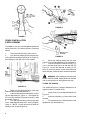
WOOD SHAPER
Model 29
Instruction Manual & Parts List
M-0460218
(800) 274-6848
www.powermatic.com
This manual has been prepared for the owner and operators of a Powermatic Model 29 Shaper.
Its purpose, aside from machine operation, is to promote safety through the use of accepted
correct operating and maintenance procedures. Completely read the safety and maintenance
instructions before operating or servicing the machine. To obtain maximum life and efficiency
from your shaper and to aid in using the machine safely, read this manual thoroughly and follow
all instructions carefully.
Warranty & Service
The JET Group warrants every product it sells. If one of our tools needs service or repair, one of our Authorized Repair Stations located throughout the United States can give you quick service.
In most cases, any one of these JET Group Repair Stations can authorize warranty repair, assist you in
obtaining parts, or perform routine maintenance and major repair on your JET, Performax or Powermatic
tools.
For the name of an Authorized Repair Station in your area, please call 1-800-274-6848.
More Information
Remember, the JET Group is consistently adding new products to the line. For complete, up-to-date product
information, check with your local JET Group distributor.
JET Group Warranty
The JET Group (including Performax and Powermatic brands) makes every effort to assure that its products
meet high quality and durability standards and warrants to the original retail consumer/purchaser of our
products that each product be free from defects in materials and workmanship as follow: 1 YEAR LIMITED
WARRANTY ON ALL PRODUCTS UNLESS SPECIFIED OTHERWISE. This Warranty does not apply to
defects due directly or indirectly to misuse, abuse, negligence or accidents, normal wear-and-tear, repair or
alterations outside our facilities, or to a lack of maintenance.
THE JET GROUP LIMITS ALL IMPLIED WARRANTIES TO THE PERIOD SPECIFIED ABOVE, FROM THE
DATE THE PRODUCT WAS PURCHASED AT RETAIL. EXCEPT AS STATED HEREIN, ANY IMPLIED
WARRANTIES OR MERCHANTIBILITY AND FITNESS ARE EXCLUDED. SOME STATES DO NOT
ALLOW LIMITATIONS ON HOW LONG THE IMPLIED WARRANTY LASTS, SO THE ABOVE LIMITATION
MAY NOT APPLY TO YOU. THE JET GROUP SHALL IN NO EVENT BE LIABLE FOR DEATH, INJURIES
TO PERSONS OR PROPERTY, OR FOR INCIDENTAL, CONTINGENT, SPECIAL, OR CONSEQUENTIAL
DAMAGES ARISING FROM THE USE OF OUR PRODUCTS. SOME STATES DO NOT ALLOW THE
EXCLUSION OR LIMITATION OF INCIDENTAL OR CONSEQUENTIAL DAMAGES, SO THE ABOVE
LIMITATION OR EXCLUSION MAY NOT APPLY TO YOU.
To take advantage of this warranty, the product or part must be returned for examination, postage prepaid, to
an Authorized Repair Station designated by our office. Proof of purchase date and an explanation of the
complaint must accompany the merchandise. If our inspection discloses a defect, we will either repair or
replace the product, or refund the purchase price if we cannot readily and quickly provide a repair or replacement, if you are willing to accept a refund. We will return repaired product or replacement at JET's expense,
but if it is determined there is no defect, or that the defect resulted from causes not within the scope of JET's
warranty, then the user must bear the cost of storing and returning the product. This warranty gives you
specific legal rights; you may also have other rights which vary from state to state.
The JET Group sells through distributors only. Members of the JET Group reserve the right to effect at any
time, without prior notice, those alterations to parts, fittings, and accessory equipment which they may deem
necessary for any reason whatsoever.
TABLE OF CONTENTS
SAFETY RULES: General .......................................................................................................................... 4
Specific ......................................................................................................................... 4
RECEIVING THE SHAPER .......................................................................................................................... 6
INSTALLATION ............................................................................................................................................. 6
Electrical Wiring ................................................................................................................................... 6
ASSEMBLY:
Fence Assembly .................................................................................................................................. 6
Miter Gauge/Clamp Assembly ............................................................................................................. 7
ADJUSTMENTS:
Belt Adjustment/Speed Change ........................................................................................................... 7
Spindle Installation & Replacement ..................................................................................................... 8
Tilting the Spindle ................................................................................................................................. 8
Raising & Lowering the Spindle ........................................................................................................... 9
Installing Cutters .................................................................................................................................. 9
Table Inserts ......................................................................................................................................... 9
Fence Adjustment ................................................................................................................................ 9
Work Hold-Downs & Safety Shield .................................................................................................... 10
OPERATION ............................................................................................................................................... 10
Shaping with the Fence ..................................................................................................................... 10
Position of Collars .............................................................................................................................. 11
Miter Gauge ........................................................................................................................................ 12
Tenoning ............................................................................................................................................. 12
Copying .............................................................................................................................................. 12
MAINTENANCE .......................................................................................................................................... 13
TROUBLE SHOOTING .......................................................................................................................... 14-15
PARTS LIST & EXPLODED VIEWS:
Fence Assembly ........................................................................................................................... 16-17
Spindle Assembly ......................................................................................................................... 18-19
Shaper Body & Miter Gauge Assemblies .................................................................................... 20-21
Tilting Frame Assembly ................................................................................................................ 22-23
ELECTRICAL SCHEMATIC ................................................................................................................... 24-25
OPTIONAL ACCESSORIES ....................................................................................................................... 26
SPECIFICATIONS
Spindle:
Diameter (standard) ........................ 1" x 4"; 3/4" x 3-1/2"; 1-1/4" x 4-3/4"
Speeds ........................................... 3000; 4000; 6000; 8000; 10,000 RPM
Rotation ......................................................................... Forward or reverse
Vertical stroke ................................................................................... 7-1/8"
Tilting ................................................................... 45o forward, 5o backward
Motor ................................................................................ 5HP, 3PH, 230/460V
Max. diameter of cutter ............................................................................. 8-7/8"
Collet chucks (optional) ........................................................................ 3/8", 1/2"
Table:
Size ................................................................................. 27-5/8" x 35-1/2"
Height .............................................................................................. 35-1/2"
Fence ........................................................................ 5-1/8" x 13-3/4" (x 2 pcs.)
Machine size ............................................................ 33-1/2" x 35-1/2" x 46-1/8"
Packing size ......................................................................... 43" x 35-1/2" x 41"
Net weight ............................................................................................... 682 lbs.
Gross weight ........................................................................................... 814 lbs.
! GENERAL SAFETY RULES
READ THE MANUAL: Always read the owner's
manual carefully before attempting to use the machine. Know the limitations and hazards associated
with its use.
INSTALLATION: If mounting machine to the floor,
use high quality anchor bolts through the mounting
holes on the base. If using a mobile base, be sure to
lock the wheels.
PROTECTION: Take every precaution to protect
yourself, others around you, and the machine itself,
from improper use.
GUARDS: Be sure machine guards are in place and
in good working order. Use them at all times on operations where they can be used. If a guard must be
removed for any operation, make sure it is replaced
immediately following completion of that operation.
HOUSEKEEPING: Before turning on machine, remove all extra equipment such as keys, wrenches,
scrap, stock, and cleaning rags from the machine.
Keep the area around machine clean and free of
scrap material and sawdust to mimimize the danger
of slipping.
ELECTRICAL GROUNDING: Your machine must
be electrically grounded. If a cord and plug are
used, make certain the grounding lug connects to a
suitable ground. Follow the grounding procedure
indicated by the National Electric Code. Keep
power tools in dry areas free from moisture.
TOOL MAINTENANCE: Clean and sharp tools
give better and safer performance. Dull tools can
cause kickback and excessive chatter. Before
making a cut, always check the condition and
adjustment of the tools. Never use a tool that is
not balanced and rated for the selected RPM.
POWER OFF: Make sure the machine is either unplugged or electrically disconnected and locked out
when performing maintenance, chaning cutters, or
service work.
CHECK DAMAGED PARTS: Check for alignment
of moving parts, binding of moving parts, breakage
of parts, mounting, and any other condition that
may affect the machine's operation. A guard or
other part that is damaged should be properly
repaired or replaced.
DO NOT USE IN DANGEROUS ENVIRONMENT:
Do not use power tools in damp or wet locations,
or expose them to rain. Keep work area well
lighted.
4
DRESS CODE: Do not wear loose clothing, neckties, jewelry, or gloves that can get caught in moving
parts. Confine long hair. Keep sleeves above the
elbow.
EYES: Always wear approved safety goggles,
glasses, or a face shield when operating this
machine. There are no exceptions to this rule.
Every day eyeglasses only have impact resistant
lenses, they ARE NOT safety glasses.
DO NOT OVERREACH: Maintain a balanced
stance and keep your body under control at all
times. Do not overreach or use excessive force to
perform any operation.
IF YOU ARE NOT thoroughly familiar with the operation of shapers, obtain advice from your supervisor, instructor or other qualified person.
DRUGS, ALCOHOL, MEDICATION: Do not operate tool while under the influence of drugs, alcohol,
or any medication.
Health Hazards. Some dust created by power
sanding, sawing, grinding, drilling and other
construction activities contains chemicals known to
cause cancer, birth defects or other reproductive
harm. Some examples of these chemicals are:
* Lead from lead-based paint.
* Crystalline silica from bricks and cement and
other masonry products.
* Arsenic and chromium from chemically-treated
lumber.
Your risk from these exposures varies, depending
on how often you do this type of work. To reduce
your exposure to these chemicals, work in a wellventilated area, and work with approved safety
equipment, such as those dust masks that are
specifically designed to filter out microscopic
particles.
! SPECIFIC SAFETY RULES
SHORT STOCK: Never shape stock less than 12
inches in length without special fixtures Where
practical, shape longer stock and cut to size.
12 INCH RULE: When shaping, never allow your
hands to come closer than 12 inches to the cutters.
HAND SAFETY: Never pass the hands directly
over or in front of the cutters. As one hand approaches the 12 inch radius point, remove it (or the
push stick) in an arc motion and reposition hands
12 inches beyond the cutters, Figure 1.
SAFETY LOCK WASHER: Never operate the
shaper without the safety locking keyed washer
located immediately under the spindle nut, Figure
3. This prevents the nut from coming loose when
the spindle is run in a counterclockwise direction.
Do not substitute any other type washer in place of
the safety lock washer.
FIGURE 1
FEED STOCK opposite to the direction of the
cutter rotation. Never back stock out of the cutter
once the cut has been started. Instead, pull the
stock straight back away from cutter and begin the
cut again. See Figure 2.
FIGURE 4
BE SURE the special arbor nut and the draw bar
are tightened on the arbor.
FIGURE 2
COLLARS: When shaping with collars, the collar
must have sufficient bearing surface (see page 11).
The work must also be fairly heavy in proportion to
the cut being made. Do not use short, lightweight
stock when shaping against collars.
MISUSE: Do not use this shaper for other than its
intended use. If used for other purposes,
POWERMATIC disclaims any real or implied
warranty and holds itself harmless for any injury
which may result from that use.
REPLACEMENT PARTS: Use only
POWERMATIC or factory authorized replacement
parts and accessories; otherwise, the shaper
warranty and guarantee will be null and void.
THE OPENING between the fence plates should
be only just enough to clear the cutter.
EDGE SHAPING: Always use the miter gauge
and clamp attachment when edge shaping stock
less than 6" wide. The fence should be removed
during this operation.
5
RECEIVING THE SHAPER
Carefully unpack the shaper and any loose items from
the wood crate and inspect for damage. Any damage should be reported to your distributor and shipping agent immediately. Before proceeding further,
read your manual thoroughly to familiarize yourself
with proper assembly, maintenance and safety procedures.
Contents of crate:
1 shaper base
1 fence body
1 fence cover
3 table inserts
1 miter gauge rod
1 miter gauge/clamp assembly
1 spindle wrench
3 arbor wrenches
1 box containing:
1 safety shield
2 hold downs
2 fence-locking handles with washers
2 fence cover knobs
3 hold down blocks (with wing nuts)
2 aluminum fence plates
2 lock blocks with knobs
1 miter gauge bar
1 draw bar
1 cabinet handle
All wiring should be done in accordance with the National Electrical Code.
Never connect the green grounding wire to a live terminal.
Make sure the voltage listed on your motor plate is
the same as that of your power source.
!
CAUTION: Running the motor on a lower
voltage may damage the motor.
ASSEMBLY
Tools required: set of open-end wrenches, phillips
screwdriver, spindle wrenches
FENCE ASSEMBLY
1.
Mount the fence body (A) to the shaper base
(B) with the two locking handles and washers (C).
Place the cover (D) atop the fence and secure with
two knobs (E). See Figure 4.
Remove the screws that hold the shaper to the shipping crate. Remove the protective coating from the
table and loose items packed with the machine. This
coating may be removed with a soft cloth moistened
with Kerosene. DO NOT use acetone, gasoline or
lacquer thinner for this purpose. DO NOT use solvents on plastic parts.
INSTALLATION
Install shaper on a level surface. Check table surface with a machinist level and, if necessary, use metal
shims under low corners. Secure to the floor with
good quality anchor bolts through the holes on the
inside bottom of the base.
ELECTRICAL WIRING
!
WARNING:
ELECTRICAL WIRING
SHOULD BE DONE BY A QUALIFIED ELECTRICIAN. THE MACHINE MUST BE PROPERLY
GROUNDED TO PREVENT INJURY FROM POSSIBLE ELECTRIC SHOCK.
The shaper must be connected to a grounded wiring
system. See schematic, page 22 and 23.
6
FIGURE 4
2.
Attach the lock blocks (F) to the connection
plates (G) with the knobs and washers, Figure 5. Slide
the aluminum fences (H) onto the lock blocks (F) as
shown.
NOTE: The knobs are spring-loaded and can be repositioned without affecting the screw; simply pull up
on the handle and reposition it on the nut located beneath the handle.
FIGURE 5
3.
Mount the dust hood (J) to the rear of the
fence body (A) with the four cross screws, Figure 6.
FIGURE 7
ADJUSTMENTS
BELT ADJUSTMENT/SPEED CHANGE
FIGURE 6
MITER GAUGE/CLAMP ASSEMBLY
The miter gauge and clamp are used for shaping the
end of stock. To assemble the miter gauge:
1.
Assemble miter gauge (A) by placing bottom
screw into hole on bar (B) and screwing knob and
washer onto threaded rod (C), Figure 7. Tighten knob.
2.
Slide miter gauge bar into table slot from the
end.
3.
Insert rod (D) and work stop (E) into the miter gauge, making sure flat side of rod is facing up.
Tighten knobs (F) on miter gauge, Figure 7.
The Model 29 Tilting Shaper is equipped with a motor and shaft pulley, Figure 8, capable of delivering
five speeds. Beginning with the top grooves on the
pulleys, the speeds are 10,000; 8,000; 6,000; and
4,000 RPM, down to the lowest groove which provides 3,000 RPM. A diagram found on the front of
the machine will aid in identifying these positions.
To change the speed and adjust the proper belt tension, proceed as follows:
1.
Disconnect machine from power source.
2.
Open front guard door.
3.
Pull handle (A) to loosen belt.
4.
Move belt (B) to the desired groove on the
pulleys.
5.
Adjust the belt tension, and push handle (A)
back in to retighten. Proper tension is reached when
the belt can be depressed about 1/8 inch to 1/4 inch
between the two pulleys, Figure 9.
FIGURE 8
7
FIGURE 11
FIGURE 9
SPINDLE INSTALLATION
& REPLACEMENT
The Model 29 can use interchangeable spindles as
well as router bits. To install the spindle, proceed as
follows:
1.
Disconnect machine from power source.
2.
Lock the main shaft by opening the rear door
in the cabinet and pulling out the knob (A), Figure 10,
and rotating it to the right until it locks in place.
FIGURE 12
6.
Unlock the shaft by rotating the lock knob
(Figure 10) to the left and allowing it to snap back in.
7.
To remove a spindle, loosen the nut (E), Figure 11, then take down the nut on the draw bar (D),
Figure 12. Loosen the draw bar by turning 2 or 3
times (H), and use hammer or other hard material to
strike the base of the draw bar to unseat the spindle.
!
WARNING: After installing and checking the
spindle, CHECK AGAIN. Make certain the draw bar
and nut, and spindle nut, are tightened securely!
TILTING THE SPINDLE
FIGURE 10
3.
Make sure the spindle and bore of the main
shaft are clean of sawdust and debris.
4.
Insert the spindle (B) into the shaft (C), matching their alignment pins, Figure 11. Then tighten up
the nut on the draw bar (D) below the pulley to seat
the spindle, Figure 12.
5.
Lock the lower spindle nut with the provided
"hook"-shaped spindle wrench (E), securing it tightly,
Figure 11. (NOTE: You will have to tilt the shaft assembly to use the spindle wrench).
8
The spindle will tilt from 5 degrees backward to 45
degrees forward. To adjust the tilt:
1.
Loosen knob (G) on the tilting handwheel (H),
Figure 13.
2.
Loosen lock handles (J) on both sides of the
machine.
3.
Turn handwheel (H) to desired position and
tighten knob (G) and handles (J).
!
WARNING: AFTER INSTALLING A CUTTER AND CHECKING IT FOR TIGHTNESS, CHECK
AGAIN! Make certain the direction of cutter is correct and that the stacking collar, safety washer and
spindle nut are all tightened securely!
!
WARNING: Be sure to release the lock knob
from the main shaft before starting machine (Figure
10).
TABLE INSERTS
FIGURE 13
RAISING & LOWERING SPINDLE
1.
Loosen the small handwheel (K), Figure 13.
2.
Turn large handwheel (L) until spindle
reaches the desired height.
3.
Retighten small handwheel (K).
Three table inserts come standard with your shaper:
a 6-3/8" (160mm) diameter, a 2-7/16" (60mm) diameter and an oval opening (for a tilted spindle). See
Figure 15. The smaller insert has a guide shoulder
of 3-3/16" (80mm) which is used for the purpose of
copying.
INSTALLING CUTTERS
1.
Disconnect machine from power source.
2.
Lock the main shaft (see Figure 10).
3.
Set the desired cutterhead (A) on the spindle,
Figure 14, making sure of the proper rotation direction (refer to illustration in "Safety Rules").
4.
Put the appropriate number of stacking collars (B) onto the spindle to attain the proper height.
FIGURE 15
FENCE ADJUSTMENT
1.
Loosen the handles (A) and move fence body
to desired position, Figure 16. Re-tighten the handles.
2.
Loosen the knob (B) and turn the fence knob
(C) until correct setting is achieved.
3.
Retighten knob (B).
FIGURE 14
5.
Place safety washer (C) on top and tighten
spindle nut (D) onto the spindle.
6.
Unlock the main shaft.
7.
To remove a cutter, reverse the above procedure.
!
CAUTION: Always include the safety washer
(C) on the spindle when operating the shaper. This
helps prevent the spindle from loosening while running in reverse.
FIGURE 16
9
Each half of the aluminum fence should be adjusted
as close to the cutterhead as possible without interfering with it. Each can be moved independently depending on the type of work to be done:
4.
Loosen the knob (D) on the connection plate
and slide aluminum fence (E) to position, Figure 16.
Retighten knob (D).
WORK HOLD-DOWNS & SAFETY SHIELD
Two hold-downs and one safety shield are included
with the shaper. One hold-down (A) presses stock
down upon the table, the other (B) keeps it pressed
against the fence. These can be mounted to the holddown base (C), Figure 17, by the use of wing-nut
blocks (D). The safety shield (E) can be mounted to
either of the hold-down pieces as shown.
FIGURE 18
When changing cutters, simply lift handle on holddown base (F), Figure 18, and flip entire assembly
back out of the way.
OPERATION
Always release the main spindle from the lock knob
before starting machine (see Figure 10).
Your shaper is equipped with pushbutton magnetic
controls. A start button, power indicator, reversing
switch, and emergency stop are all located on the
front of the machine.
To reverse the rotation of the spindle, simply shut off
the motor and engage the reversing switch.
FIGURE 17
The hold-down base is factory adjusted to maintain
vertical positioning of the rod. However, if adjustment
is ever necessary, raise the handle (F) and loosen
nut (G) with a wrench. Then turn the socket head
screw (H) with an allen wrench, in or out until the rod
is vertical. See Figure 18. When satisfied, re-tighten
the nut (G). Loosen the soc. hd. screws (J) on the
handle and adjust the eccentric washers behind them
so that the handle can be lowered all the way but still
maintain a degree of tightness. Re-tighten screws.
!
CAUTION: NEVER attempt to reverse the rotation of the spindle while the motor is running.
SHAPING WITH THE FENCE
Using the fence is the safest and most satisfactory
method of shaping, and should always be used when
the work permits. Almost all straight work can be
used with the fence.
1.
For normal work, where a portion of the original edge of the stock is not touched by the cutter,
both the infeed and outfeed fence are in a straight
line, Figure 19.
FIGURE 19
10
2.
When the shaping operation removes the
entire edge of the stock, e.g. in jointing or making a
full bead, the shaped edge will not be supported by
the outfeed fence when both fences are in line, Figure 20a. In this case, the stock should be advanced
to the position shown in Figure 20a and stopped. The
outfeed fence should then be moved forward to contact the work, Figure 20b. The outfeed fence will then
be in line with the cutting circle and the operation can
continue.
FIGURE 21b
FIGURE 20a
The collars may be used in any of the following positions: above, below, or between the cutters.
1.
When the collar is used below the cutter, as
in Figure 22, the progress of the cut can be seen
throughout the operation. However, any accidental
lifting of the work will gouge the wood and ruin the
workpiece.
FIGURE 20b
FIGURE 22
POSITION OF COLLARS
When shaping with collars, the collar must have sufficient bearing surface, as shown in Figure 21a. Also
the work must be fairly heavy relative to the cut being
made. Under no circumstances should a short, light
workpiece be shaped against the collars, as in Figure 21b.
2.
When the collar is used above the cutter, as
in Figure 23, the cut can not be seen; but this method
offers an advantage in that the cut is not affected by
slight variations in the thickness of the stock.
Also, accidental lifting of the workpiece will not gouge
the workpiece; simply repeat the operation to correct
the mistake.
FIGURE 23
3.
Using the collar between two cutters has the
advantages and disadvantages of the first two procedures, and is frequently used where both edges of
the work are to be molded; see Figure 24.
FIGURE 21a
11
!
CAUTION: When using tenoning cutters with
a diameter of 11-13/16" or 9-13/16", run spindle at a
speed not higher than 3,000 RPM. If tenoning cutters have a diameter of 7-7/8" or 6- 3/8", run spindle
at a speed not higher than 6,000 RPM. If tenoning
cutters have a diameter no larger than 3-3/16", run
spindle at 10,000 RPM.
FIGURE 24
NOTE: It is advisable to place the cutter as low as
possible on the spindle to reduce spindle deflection
and ensure the best possible finish. Also make sure
that the contacting surfaces of the cutter are smooth,
clean and without dents.
MITER GAUGE
The miter gauge is used for shaping the end of stock,
usually requiring removal of the fence. To edgeshape, place the stock against the gauge as shown,
Figure 25. Tighten clamp (A) firmly against stock and
adjust work stop (B) against rear edge of stock. Push
work past cutterhead.
The miter gauge can be adjusted to shape at an angle
by loosening the knob (C) and rotating the gauge body
to the desired angle on the indicator (D).
COPYING
When using the same procedure on multiple
workpieces, a jig or template can be made to facilitate the operation:
1.
Prepare the jig (A), Figure 26, to accomodate
your original workpiece.
2.
Place the jig (A) against the table insert guide
shoulder (B).
3.
Fasten the new workpiece (C) on the jig (A)
with the clamp (D) and push the assembly past the
cutter.
FIGURE 26
FIGURE 25
The Shaper can be used for molds, rabbets, grooves,
tenons, copying, etc.:
TENONING
The provided miter gauge and clamp can be used for
tenoning operations.
12
MAINTENANCE
8cT\
?^bXcX^]
8]cTaeP[
BdXcPQ[Tch_Tb^U^X[
5XV=^
1
DQR\U?`U^Y^W
6bUaeU^d\i
=QSXY^U?Y\
"(
2
3_^^USdY_^@\QdU
6bUaeU^d\i
=QSXY^U?Y\
")
3
=QY^CXQVd
=_^dX\i
CXU\\1\fQ^YQ7bUQcUB"
"(
FIGURE 27
Apply a drop of light machine oil occasionally on the
ledge and wall of the table opening to facilitate the
changing of table inserts.
The bearings in the motor are sealed for life and do
not require lubrication.
The main shaft should be lubricated with grease regularly after continuous running for 30 days. See chart.
FIGURE 28
13
Trouble-Shooting for Model 29 Shaper
PROBLEM
POSSIBLE CAUSE
SOLUTION
Shaper will not start.
1. Fuse blown or circuit breaker tripped.
2. Cord damaged.
1. Replace fuse or reset circuit breaker.
2. Have cord replaced by authorized
service person.
Overload kicks out
frequently.
1. Extension cord too light or too long.
2. Stock being fed too quickly.
3. Cutter is dull or has gum on it.
1. Replace with adequate size cord.
2. Feed stock more slowly.
3. Clean or replace cutter.
Cutterhead does not
come up to speed.
1. Extension cord too light or too long.
2. Low current.
3. Motor not wired for correct voltage.
1. Replace with adequate size cord.
2. Contact local electric company.
3. Refer to motor name plate for correct
wiring.
4. Release spindle lock knob.
4. Spindle is locked.
Shaper makes
unsatisfactory cuts.
1. Dull cutter.
2. Gum or pitch on cutter.
3. Gum or pitch on table causing erratic feed.
4. Feeding work in wrong direction.
Stock burns.
1. Dull cutter.
2. Cutting too deep.
3. Forcing work.
Machine vibrates
excessively.
1. Damaged cutterhead.
2. Stand or bench on uneven floor.
3. Bad v-belt.
4. V-belt not tensioned correctly.
5. Bent pulley.
6. Improper motor mounting.
Edge splits off on
1. Characteristic of cut.
1. Replace cutter.
2. Remove cutter and clean with
turpentine and steel wool.
3. Clean table with turpentine and
steel wool.
4. Feed work against cutter rotation.
1. Sharpen by honing on flat side.
2. On hardwoods take light cuts; attain
full depth of cut with several passes.
3. Feed slowly and steadily.
1. Replace cutterhead.
2. Reposition on flat, level surface.
3. Replace belt.
4. Adjust belt tension by moving motor
bracket.
5. Replace pulley.
6. Check and adjust motor mounting.
1. Make cross-grain cuts first then finish
with grain. Use scrap block to support
at end of cut.
Raised areas on shaped 1. Variation in pressure which holds work
edge.
against cutter.
1. Keep work firmly against fence or
collars throughout pass. Use holddowns.
Work pulled from hand
of cut.
1. Use mitre gauge with hold-down to
start cut when shaping freehand; hold
work firmly against fence.
Adjust the tension of spring plate.
1. No support.
Depth of cut not uniform. 1. Misalignment.
2. Side pressure not uniform.
1. Adjust outfeed fence.
2. Use hold-downs; keep pressure
against fence or collars consistent.
Variation in height of cut. 1. Variation in pressure which holds work
1. Keep pressure firm throughout pass.
Use hold-downs. Make pass slowly
and steadily. Whenever possible,
keep cutter under stock.
14
Trouble-Shooting for Model 29 Shaper
(continued)
PROBLEM
POSSIBLE CAUSE
SOLUTION
Cuts not smooth.
1. Wrong R.P.M.
2. Feed too fast.
3. Working against grain.
4. Cutting too deep.
1. Use faster speed.
2. Pass stock more slowly.
3. Work with grain whenever possible.
4. On very deep cuts make several
passes.
Spindle does not raise
freely.
1. Sawdust and dirt in raising mechanisms.
1. Brush or blow out loose dust and dirt.
15
PARTS LIST: Fence Assembly (29 Shaper)
(6293192 - Items 1 thru 18 & 35 thru 54)
NO. PART NO.
DESCRIPTION
NO. PART NO.
DESCRIPTION
1
2
3
4
5
6
7
8
9
10
11
12
13
14
15
16
17
18
19
20
21
22
23
24
25
26
27
28
CHUTE, DUST
SCREW, HEX. SOC. SET M8 X 20
KNOB, ADJUSTMENT
PLATE
SCREW, ADJ.
RAM
HANDLE, LOCK
WASHER
CAP, R.H.
BLOCK, R.H.
BLOCK, L.H.
SCREW, HEX. SOC. HD. M6 X 30
FENCE, R.H.
FENCE, L.H.
GUIDE
CAP, L.H.
WASHER, FLAT M8
LEVER, LOCK
GUIDE
BAR, HORIZONTAL
BAR, HORIZONTAL
CLIP
BLOCK
BAR, VERTICAL
BAR, VERTICAL
WASHER, SPRING M6
BODY, FENCE
SCREW, HEX. SOC. HD. M6 X 10
29
30
31
32
33
34
35
36
37
38
39
40
42
43
44
45
46
47
48
49
50
51
52
53
54
LABEL, WARNING
KNOB, LOCK
SHIELD
WASHER, SPRING M6
SCREW, CHEESE HD. M6 X 20
GUIDE
NUT, HEX. M8
SCREW, HEX. SOC. SET M8 X 35
WASHER, SPRING M5
NUT, LOCK M5
WASHER, CAM
SCREW, HEX. SOC. HD. M5 X 10
LATCH
BRACKET
SCREW, HEX. SOC. HD. M8 X 30
WASHER, SPRING M8
NUT, HEX. M8
PLATE
WASHER, FLAT M8
KNOB, M8 w/ STUD
SCREW, HEX. SOC. HD. M5 X 12
BAR, VERTICAL
KNOB, w/ STUD
WASHER, FLAT M8
SCREW, CHEESE HD., M8 X 12
WORK HOLD-DOWN GUIDES
(Items 19 thru 34)
16
6292984
6292985
6292986
6292987
6292988
6292989
6292990
6292991
6292992
6292993
6292994
6292995
6292996
6292997
6292998
6292999
6293000
6293001
6293002
6293003
6293004
6293005
6293006
6293007
6293008
6293009
6293010
6293011
6293012
6293013
6293014
6293009
6293015
6293016
6293017
6293018
6293019
6293020
6293021
6293022
6293023
6293024
6293025
6293026
6293017
6293027
6293000
6293028
6293029
6293030
6293031
6293000
6293032
6293194
Fence Assembly (29 Shaper)
17
PARTS LIST:
Spindle Assembly (29 Shaper)
NO. PART NO.
DESCRIPTION
NO. PART NO.
DESCRIPTION
1
NUT, 3/4" SPINDLE
NUT, 1" SPINDLE
NUT, 1-1/4" SPINDLE
WASHER, KEYED
SET, SPACER 3/4"
SET, SPACER 1"
SET, SPACER 1-1/4"
NUT, RETAINER
NUT, COLLET
BUSHING, 1/4"
CHUCK, 1/2" COLLET
SPINDLE, INTERCHANGEABLE
3/4"
SPINDLE, INTERCHANGEABLE
1"
SPINDLE, INTERCHANGEABLE
1-1/4"
SCREW, HEX. SOC. HD. M5 X 16
10
11
12
13
14
15
16
17
18
19
20
21
PLATE
BEARING
KEY, 6 X 54
RING, RETAINING
SPINDLE
SPRING, DISK, 61.5 X 40.5 X 0.7
BEARING
SPACER
PULLEY, SPINDLE
NUT
SCREW, HEX. SOC. SET, M6 X 6
BELT
3/4" INTERCHANGEABLE
SPINDLE ASSY. (Items 1, 2, 3, 8)
1" INTERCHANGEABLE
SPINDLE ASSY. (Items 1, 2, 3, 8)
1-1/4" INTERCHANGEABLE
SPINDLE ASSY. (Items 1, 2, 3, 8)
2
3
4
5
6
7
8
6293033
6293034
6293035
6293036
6293037
6293038
6293039
6293040
6293041
6293042
6293043
6293044
6293045
6293046
9
18
6293047
6293048
6293049
6293050
6293051
6293052
6293053
6293054
6293055
6293056
6293057
6293058
6293059
6293195
6293196
6293197
Spindle Assembly (29 Shaper)
19
PARTS LIST:
Shaper Body & Mitre Gauge Assemblies (29 Shaper)
NO. PART NO.
DESCRIPTION
NO. PART NO.
DESCRIPTION
1
2
3
4
5
6
7
8
10
11
12
13
14
15
16
17
18
19
20
21
22
23
24
25
26
27
28
29
30
31
32
33
34
35
36
37
38
RING, INSERT
RING, INSERT
SCREW, HEX. SOC. HD. M5 X 12
SCREW, HEX. SOC. HD. M5 X 16
RING, INSERT
TABLE
WASHER, M12
CABINET
SCREW, HEX. SOC. M12 X 45
COVER, SWITCH
PANEL
SCREW, CHEESE HD., M4 X 10
BUTTON, START
BUTTON, STOP
LAMP, PILOT
SWITCH, FWD.-REV.
HANDLE
LATCH
LABEL
LABEL
NUT, HEX. M10
SCREW, FIXED
SPRING
KNOB
HANDWHEEL
WASHER, M12
NUT, CUP M12
KNOB, M8
LABEL
LABEL
LABEL
BASE, INDICATOR SCALE
LABEL
BASE, TERMINAL
SCREW, CHEESE HD. M4 X 10
SEAL
COVER
39
40
41
42
43
44
6293094
6293095
6293096
6293097
6293098
6293099
45
46
47
48
49
50
51
52
53
54
55
56
57
58
59
60
61
62
63
64
65
66
6293100
6293101
6293102
6293103
6293104
6293105
6293106
6293107
6293108
6293109
6293110
6293111
6293112
6293113
6293114
6293115
6293116
6293107
6293117
6293118
6293119
6293120
67
68
69
70
6293121
6293122
6293119
6293123
6293193
LABEL
SCREW, CHEESE HD. M6 X 16
SCREW, CHEESE HD. M5 X 12
COVER
LATCH
SCREW, HEX. SOC. FLAT HD.
M5 X 12
PIN
BRACKET
SCREW, HEX. SOC. SET M6 X 12
PAD
LEVER
PLUNGER
SPRING
SCREW, HEX. SOC. SET M8 X 12
ROD, HORIZONTAL
ROD, VERTICAL
BLOCK
WASHER, LOCK M10
SCREW, HEX. SOC. M10 X 35
KNOB
STUD
WASHER, M10
BODY
SCREW, HEX. SOC. SET M8 X 12
STUD, PIVOT
BAR, GUIDE
KNOB w/ STUD
SCREW, HEX. SOC. FLAT HD.
M4 X 10
NUT, RETAINER
ROD
KNOB w/ STUD
BLOCK, STOP
MITRE GAUGE ASSY. (Items
45 thru 70)
20
6293060
6293061
6293029
6293062
6293063
6293064
6293065
6293066
6293067
6293068
6293069
6293070
6293071
6293072
6293073
6293074
6293075
6293076
6293077
6293078
6293079
6293080
6293081
6293082
6293083
6293065
6293084
6293085
6293086
6293087
6293088
6293089
6293090
6293091
6293070
6293092
6293093
Shaper Body & Mitre Gauge Assemblies (29 Shaper)
21
PARTS LIST: Tilting Frame Assembly (29 Shaper)
NO. PART NO.
DESCRIPTION
NO. PART NO.
DESCRIPTION
1
2
3
4
5
6
6293124
6293115
6293125
6293126
6293127
6293128
7
8
9
10
11
12
13
14
15
16
17
18
19
20
21
22
23
24
25
26
27
28
29
30
31
32
33
34
35
36
37
38
39
40
41
42
43
6293129
6293130
6293131
6293132
6293115
6293133
6293134
6293135
6293017
6293136
6293000
6293025
6293062
6293137
6293138
6293139
6293140
6293141
6293142
6293143
6293144
6293145
6293146
6293115
6293147
6293148
6293149
6293150
6293151
6293152
6293153
6293000
6293154
6293155
6293156
6293157
6293158
SCREW, HEX SOC. HD. M10 X 35
WASHER, M10
PULLEY MOTOR
BUSHING
RETAINER
SCREW, HEX. SOC. SET,
M10 X 35
NUT, HEX. M10
PLATE, MOTOR
HANDLE, ADJ. BELT
SCREW, HEX. SOC. HD M10 X 30
WASHER, M10
SPACER
STUD
SCREW, CHEESE HD. M8 X 16
NUT, HEX. M8
LINK
WASHER, M8
SCREW, HEX. SOC. HD. M8 X 30
SCREW, HEX. SOC. HD. M5 X 16
HANDLE, L.H.
BUSHING, L.H.
FRAME, INCLINING
SCREW, HEX SOC. HD. M10 X 50
SPACER
FRAME, INCLINING, L.H.
BOARD, SLOPE
SCREW, HEX. SOC. HD M10 X 25
NUT, HEX. M16
SUPPORT
WASHER, M10
SCREW, HEX SOC. HD. M10 X 45
GEAR
PLATE, MOTOR
COVER, WORM
NUT, HEX. M16
SCREW, HEX. SOC. HD M8 X 10
STUD
WASHER, M8
SCREW, HEX. SOC. HD M8 X 16
SCREW, HEX. SOC. HD M8 X 20
BOLT, DRAW
WASHER
NUT, HEX. M12
44
45
46
47
48
49
50
51
52
53
54
55
56
57
58
59
60
61
62
63
64
65
66
67
68
69
70
71
72
73
74
75
76
77
78
79
BOLT, WORM
KEY, 4 X 24
SHAFT, WORM
KEY, 4 X 24
HANDLE, PLASTIC
SOCKET, FIXED
SCREW, HEX. SOC. HD M6 X 30
RING, RETAINING
HANDWHEEL
NUT, HEX. M25
HANDWHEEL
WASHER, 1/2"
NUT, CAP 1/2"
BUSHING
SHAFT
SPRING
NUT
SCREW, HEX. SOC. SET M6 X 25
KNOB
SLEEVE
SCREW, HEX. SOC. HD M6 X 16
KEY
NUT, FIXED
SCREW, HEX. SOC. HD M4 X 16
GEAR
WASHER, M8
FRAME, INCLINING R.H.
SCREW, HEX. SOC. HD M8 X 40
BUSHING, R.H.
HANDLE, R.H.
SCREW, HEX. SOC. HD M5 X 22
COVER
BEARING
SHAFT, WORM
COVER
MOTOR, 5 HP 3 Ph
BOX, CONTROL
WRENCH, SPANNER
WRENCH, 41mm, 1-1/4" SPINDLE
WRENCH, 38mm, 1" SPINDLE
WRENCH, 32mm, 3/4" SPINDLE
BOX, TOOL (6 pc. set open-end
wrenches, grease gun, hex key
wrench set)
22
6293159
6293160
6293161
6293160
6293162
6293163
6293164
6293165
6293166
6293167
6293168
6293169
6293170
6293171
6293172
6293173
6293174
6293175
6293176
6293177
6293178
6293179
6293180
6293181
6293182
6293000
6293183
6293184
6293185
6293186
6293187
6293188
6293189
6293190
6293191
6292983
6292982
6292978
6292979
6292980
6292981
6292975
Tilting Frame Assembly (29 Shaper)
23
ELECTRICAL SCHEMATIC: Model 29 Tilting Shaper
THREE PHASE
Y- D START
(2-STEP SWITCH)
PAR T N O.
24
D ESC R IPTION
TYPE
SPEC IFIC ATION
6293074
FOR-REV SWITC H
CS
25A 1a
6293072
STOP
PB1
10A 250VAC 1b
6293071
START
PB2
10A 250VAC 1a
6292977
MAGNETIC C ONTAC TOR
MC 1
MA15
6292976
THERMAL RELAY
O.L.
RH-15
6293073
PILOT LAMP
WL
ELECTRICAL SCHEMATIC: Model 29 Tilting Shaper
THREE PHASE
24V
PAR T N O.
D ESC R IPTION
TYPE
SPEC IFIC ATION
6293200
C ONTROL C IRC UIT TRANSFORMER
Tr.
PT54
6293074
FOR-REV SWITC H
CS
25A 1a
6293072
STOP
PB1
10A 250VAC 1b
6293071
START
PB2
10A 250VAC 1a
6292974
MAGNETIC C ONTAC TOR
MC 1
MA15 24VAC
6292976
THERMAL RELAY
O.L.
RH-15
6292973
PILOT LAMP
WL
24VAC
25
OPTIONAL ACCESSORIES Model 29 Tilting Shaper
6293198
6293199
6293200
26
1" Spindle Assembly, 6" under the nut.
1-1/4" Spindle Assembly, 6" under the nut.
460V transformer.
To order parts or reach our service department, please call our toll-free number between 8:00 a.m. and 4:30 p.m.
(CST), Monday through Friday. Having the Model Number and Serial Number of your machine available when
you call will allow us to serve you quickly and accurately. Locating the stock number of the part(s) required from
your parts manual will also expedite your order.
Phone No.: (800) 274-6848
Fax No.
(800) 274-6840
If you are calling from Canada, please call 800-238-4746
E-mail:
[email protected]
Website: www.powermatic.com
27
04/01
JET Equipment & Tools
P.O. Box 1349
Auburn, WA 98071-1349
Phone: (800) 274-6848
Fax: (800) 274-6840
E-mail: [email protected]
Website: www.powermatic.com
C
POWERMATIC
ALL RIGHTS RESERVED