1
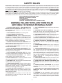
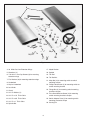
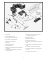
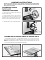
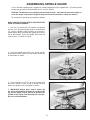
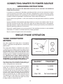
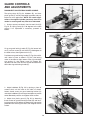
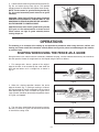
(Model 43-420) DATED 9-17-99 PART NO. 432-02-651-0012 ©Delta International Machinery Corp. 1999 INSTRUCTION MANUAL Platinum Edition 2-Speed Heavy-Duty Wood Shaper TABLE OF CONTENTS SAFETY RULES ...............................................................................................................................................................3 ADDITIONAL SAFETY RULES FOR SHAPERS .............................................................................................................4 UNPACKING AND CLEANING.........................................................................................................................................5 ASSEMBLY INSTRUCTIONS Assembling Spindle Raising And Lowering Handwheel ....................................................................................8 Assembling Extension Wings To Shaper Table....................................................................................................8 Assembling Switch Bracket And On/Off Switch..................................................................................................9 Assembling Fence To Shaper Table ....................................................................................................................10 Assembling Guards To Fence Body....................................................................................................................12 Assembling And Changing Spindles..................................................................................................................13 Assembling Table Inserts ....................................................................................................................................14 Assembling Cutters And Collars To Spindle......................................................................................................14 Assembling Spindle Guard..................................................................................................................................15 CONNECTING SHAPER TO POWER SOURCE Grounding Instructions........................................................................................................................................16 Single Phase Operation .......................................................................................................................................16 Three Horsepower Motors ...................................................................................................................................16 OPERATING CONTROLS AND ADJUSTMENTS Starting And Stopping The Shaper .....................................................................................................................17 Locking Switch In The “OFF” Position................................................................................................................17 Raising And Lowering Spindle............................................................................................................................18 Changing Speeds And Adjusting Belt Tension .................................................................................................18 Reversing Spindle Rotation.................................................................................................................................18 Fence Controls And Adjustments.......................................................................................................................19 Guard Controls And Adjustments ......................................................................................................................20 OPERATIONS Shaping When Using The Fence As A Guide.....................................................................................................21 Shaping With Collars And Starting Pin ..............................................................................................................22 Position Of Collars ..........................................................................................................................................22 Starting Pin ......................................................................................................................................................23 REPLACING SPINDLE CARTRIDGE ............................................................................................................................23 ACCESSORIES .........................................................................................................................................................24-27 PARTS, SERVICE OR WARRANTY ASSISTANCE .......................................................................................................28 WARRANTY....................................................................................................................................................................28 2 SAFETY RULES Woodworking can be dangerous if safe and proper operating procedures are not followed. As with all machinery, there are certain hazards involved with the operation of the product. Using the machine with respect and caution will considerably lessen the possibility of personal injury. However, if normal safety precautions are overlooked or ignored, personal injury to the operator may result. Safety equipment such as guards, push sticks, hold-downs, featherboards, goggles, dust masks and hearing protection can reduce your potential for injury. But even the best guard won’t make up for poor judgment, carelessness or inattention. Always use common sense and exercise caution in the workshop. If a procedure feels dangerous, don’t try it. Figure out an alternative procedure that feels safer. REMEMBER: Your personal safety is your responsibility. This machine was designed for certain applications only. Delta Machinery strongly recommends that this machine not be modified and/or used for any application other than that for which it was designed. If you have any questions relative to a particular application, DO NOT use the machine until you have first contacted Delta to determine if it can or should be performed on the product. DELTA INTERNATIONAL MACHINERY CORP. MANAGER OF TECHNICAL SERVICES 246 ALPHA DRIVE PITTSBURGH, PENNSYLVANIA 15238 (IN CANADA: 644 IMPERIAL ROAD, GUELPH, ONTARIO N1H 6M7) WARNING: FAILURE TO FOLLOW THESE RULES MAY RESULT IN SERIOUS PERSONAL INJURY 15. DON’T OVERREACH. Keep proper footing and balance at all times. 1. FOR YOUR OWN SAFETY, READ INSTRUCTION MANUAL BEFORE OPERATING THE TOOL. Learn the tool’s application and limitations as well as the specific hazards peculiar to it. 16. MAINTAIN TOOLS IN TOP CONDITION. Keep tools sharp and clean for best and safest performance. Follow instructions for lubricating and changing accessories. 2. KEEP GUARDS IN PLACE and in working order. 17. DISCONNECT TOOLS before servicing and when changing accessories such as blades, bits, cutters, etc. 3. ALWAYS WEAR EYE PROTECTION. 4. GROUND ALL TOOLS. If tool is equipped with threeprong plug, it should be plugged into a three-hole electrical receptacle. If an adapter is used to accommodate a twoprong receptacle, the adapter lug must be attached to a known ground. Never remove the third prong. 18. USE RECOMMENDED ACCESSORIES. The use of accessories and attachments not recommended by Delta may cause hazards or risk of injury to persons. 19. REDUCE THE RISK OF UNINTENTIONAL STARTING. Make sure switch is in “OFF” position before plugging in power cord. 5. REMOVE ADJUSTING KEYS AND WRENCHES. Form habit of checking to see that keys and adjusting wrenches are removed from tool before turning it “on.” 20. NEVER STAND ON TOOL. Serious injury could occur if the tool is tipped or if the cutting tool is accidentally contacted. 6. KEEP WORK AREA CLEAN. Cluttered areas and benches invite accidents. 9. MAKE WORKSHOP CHILDPROOF – with padlocks, master switches, or by removing starter keys. 21. CHECK DAMAGED PARTS. Before further use of the tool, a guard or other part that is damaged should be carefully checked to ensure that it will operate properly and perform its intended function – check for alignment of moving parts, binding of moving parts, breakage of parts, mounting, and any other conditions that may affect its operation. A guard or other part that is damaged should be properly repaired or replaced. 10. DON’T FORCE TOOL. It will do the job better and be safer at the rate for which it was designed. 22. DIRECTION OF FEED. Feed work into a blade or cutter against the direction of rotation of the blade or cutter only. 11. USE RIGHT TOOL. Don’t force tool or attachment to do a job for which it was not designed. 23. NEVER LEAVE TOOL RUNNING UNATTENDED. TURN POWER OFF. Don’t leave tool until it comes to a complete stop. 7. DON’T USE IN DANGEROUS ENVIRONMENT. Don’t use power tools in damp or wet locations, or expose them to rain. Keep work area well-lighted. 8. KEEP CHILDREN AND VISITORS AWAY. All children and visitors should be kept a safe distance from work area. 12. WEAR PROPER APPAREL. No loose clothing, gloves, neckties, rings, bracelets, or other jewelry to get caught in moving parts. Nonslip footwear is recommended. Wear protective hair covering to contain long hair. 24. DRUGS, ALCOHOL, MEDICATION. Do not operate tool while under the influence of drugs, alcohol or any medication. 13. ALWAYS USE SAFETY GLASSES. Wear safety glasses. Everyday eyeglasses only have impact resistant lenses; they are not safety glasses. Also use face or dust mask if cutting operation is dusty. 25. MAKE SURE TOOL IS DISCONNECTED FROM POWER SUPPLY while motor is being mounted, connected or reconnected. 26. WARNING: The dust generated by certain woods and wood products can be injurious to your health. Always operate machinery in well ventilated areas and provide for proper dust removal. Use wood dust collection systems whenever possible. 14. SECURE WORK. Use clamps or a vise to hold work when practical. It’s safer than using your hand and frees both hands to operate tool. 3 ADDITIONAL SAFETY RULES FOR WOOD SHAPERS 1. WARNING: DO NOT OPERATE YOUR WOOD SHAPER UNTIL IT IS COMPLETELY ASSEMBLED AND INSTALLED ACCORDING TO THE INSTRUCTIONS. 20. ALWAYS feed against the cutter rotation, as shown in Fig. A. 2. IF YOU ARE NOT thoroughly familiar with the operation of Wood Shapers, obtain advice from your supervisor, instructor or other qualified person. 3. MAKE SURE wiring codes and recommended electrical connections are followed and that machine is properly grounded. Fig. A 21. WHEN SHAPING with collars and starting pin, the collar MUST have sufficient bearing surface, as shown in Fig. B. Fig. C, illustrates the wrong way for this operation as the collar DOES NOT have sufficient bearing surface. 4. NEVER turn the shaper “ON” before clearing the table of all objects (tools, scraps of wood, etc.). 5. DO NOT process materials less than 12 in length or 4 in width without special supporting fixtures. Use push sticks, featherboards or holddowns whenever possible. 6. ALWAYS use a miter gage and clamp attachment when edge shaping work less than 6 wide. The fence should be removed during this operation. 7. AVOID awkward hand positions where a sudden slip could allow your hand to contact the cutter. Fig. B 8. KEEP hands away from cutting tool. 9. NEVER run the stock between the fence and the cutter. 10. DO NOT feed material that is warped, contains knots or is embedded with foreign objects, such as nails or staples. 11. NEVER start the shaper with the stock in contact with the cutter. Fig. C 12. NEVER reach under the table while the machine is running. 22. WHEN SHAPING with collars and starting pin, the work must be fairly heavy in proportion to the cut being made as shown in Fig. D. UNDER NO CIRCUMSTANCES should short work of light body be shaped against the collars as shown in Fig. E. 13. NEVER perform layout, assembly or set-up work on the table while the shaper is operating. 14. KEEP cutters sharp and free from rust and pitch. 15. THE FENCE halves should be adjusted so that the cutter opening is never more than is required to clear the cutter. 16. ALWAYS lock fence hardware after making fence adjustments. Fig. D 17. MAKE CERTAIN cutters are properly secured before starting machine. 18. DO NOT perform any operation freehand. ALWAYS use fence for straight shaping; miter gage for edge shaping; and starting pin and rub collars for curve shaping. Fig. E 19. ALWAYS keep front motor access panel closed while operating shaper. 4 ADDITIONAL SAFETY RULES FOR WOOD SHAPERS (continued) 23. WHEN SHAPING with collars and starting pin, the cutter should be positioned below the collar whenever possible, as shown in Fig. F. 27. SHOULD any part of your shaper be missing, damaged or fail in any way, or any electrical component fail to perform properly, shut off switch and remove plug from power supply outlet. Replace missing, damaged or failed parts before resuming operation. 28. ADDITIONAL INFORMATION regarding the safe and proper operation of this product is available from the National Safety Council, 1121 Spring Lake Drive, Itasca, IL 60143-3201, in the Accident Prevention Manual for Industrial Operations and also in the Safety Data Sheets provided by the NSC. Please also refer to the American National Standards Institute ANSI 01.1 Safety Requirements for Woodworking Machinery and the U.S. Department of Labor OSHA 1912.213 Regulations. Fig. F 24. MAKE all adjustments with the power “OFF”. 25. KEEP guard in place at all times. 29. SAVE THESE INSTRUCTIONS. Refer to them often and use them to instruct others. 26. BEFORE leaving the machine, make sure the work area is clean. UNPACKING AND CLEANING Carefully unpack the shaper and fence system from the shipping containers. Clean all loose parts and remove the protective coating from the machined surfaces of the shaper table. This coating may be removed with a soft cloth moistened with kerosene (do not use acetone, gasoline, or lacquer thinner for this purpose). Figures 2 and 3, illustrate the shaper and all loose items supplied with the machine. Fig. 4, illustrates the items supplied with the fence system. Fig. 2 5 4 5 7 16 8 15 6 14 17 13 26 9 12 18 25 11 23 19 24 10 22 20 21 Fig. 3 4. 10 Wide Cast Iron Extension Wings 17. Keyed Washer 5. Wrenches (2) 18. Spindle 6. 7/16-20 x 1 Hex Cap Screws (6) for mounting extension wings 19. Tie Rod 20. Tie Rod Nut 7. Flat Washers (6) for mounting extension wings 21. Keps Nut (2) for mounting switch-to-switch mounting bracket 8. Handwheel 9. Key for Handwheel 22. Phillips Head Screw (2) for mounting switch-toswitch mounting bracket 10. Lock Knob 23. Flange Nut (4) for mounting switch mounting bracket to shaper 11. Guard 12. 3/4 I.D. Washer (2) 24. Truss Head Machine Screw (4) for mounting switch mounting bracket to shaper 13. 3/4 I.D. x 1/2 Thick Collar 14. 3/4 I.D. x 3/4 Thick Collar 25. Switch Adapter Plate (2) for mounting switch mounting bracket to shaper 15. 3/4 I.D. x 1 Thick Collar 26. Starting Pin 16. Spindle Nut 6 27 28 32 29 45 33 38 44 31 35 37 34 36 40 30 39 42 43 41 Fig. 4 27. Fence Body 37. Hex Soc. Hd. Screw (4) for mounting guard mounting bracket to top cover 28. Left and Right fence halves 38. Rod for fence guard 29. Locking Levers (2) for fence halves 39. Holddown for fence guard 30. Flat Washers (2) for locking levers 40. Brackets for fence guard (4) 31. Spring clamp for fence guard 41. Flat washers (2) for mounting top cover to fence body 32. Top cover 33. Guard Mounting Bracket 42. Lock Knobs (2) for mounting top cover to fence body 34. Clear Plastic Guard 43. Flat Washers (2) for fence locking handles 35. Hex Nuts (4) for mounting guard mounting bracket to top cover 44. Fence Locking Handles (2) for mounting fence to shaper 36. Lock Washers (8) for mounting guard mounting bracket to top cover 45. Lock Bars (23) for fence halves 7 ASSEMBLY INSTRUCTIONS WARNING: FOR YOUR OWN SAFETY, DO NOT CONNECT THE SHAPER TO THE POWER SOURCE UNTIL THE SHAPER IS COMPLETELY ASSEMBLED AND YOU HAVE READ AND UNDERSTOOD THE ENTIRE INSTRUCTION MANUAL. ASSEMBLING SPINDLE RAISING AND LOWERING HANDWHEEL A B 1. Insert key (A) Fig. 5, into slot in spindle raising and lowering shaft (B) as shown. D C 2. Assemble handwheel (C) Fig. 5, onto spindle shaft (B), making certain the key (A) fits into the slot (D) in the handwheel. Insert the set screw which holds the handwheel to the shaft and tighten screw firmly against key. Fig. 5 3. Thread lock knob (E) Fig. 6, into the spindle shaft (B). B E Fig. 6 ASSEMBLING EXTENSION WINGS TO SHAPER TABLE 1. Assemble extension wing (A) Fig. 7, to shaper table (B) using three 1-1/4 inch-long hex head screws (C) and flat washers (D) supplied. Use a straight edge (E) Fig. 7, to make certain the extension wing is level with shaper table before tightening three screws (C). Assemble and level remaining extension wing in the same manner. 2. Fig. 8, illustrates both extension wings assembled to shaper table. B D C C D A Fig. 7 8 Fig. 8 G B H F A B F E G H D L F K L K C C Fig. 9 Fig. 10 H ASSEMBLING SWITCH BRACKET AND ON/OFF SWITCH 1. The on/off switch (A) Fig. 9, and switch mounting bracket (B) are shipped inside the shaper cabinet. Open the side door of the shaper cabinet, remove switch package and remove packaging material. H 2. Position switch mounting bracket (B) Fig. 10, so holes (C) are over hole (D) in shaper cabinet (E), then fasten bracket (B) to cabinet (E) using four truss head screws (F) Fig. 9, flange nuts (G) and two switch adapter plates (H). NOTE: Switch adapter plates (H) are to be positioned inside the shaper cabinet as shown in Fig. 11. Fig. 11 3. Fig. 12, illustrates switch mounting bracket (B) properly mounted to shaper cabinet. J 4. Assemble on/off switch (A) Fig. 9, to switch mounting bracket (B) Fig. 12, through two holes (J), using two Phillips head screws (K) Fig. 9, and Keps nuts (L). Fig. 12 5. Fig. 13, illustrates on/off switch properly mounted to switch mounting bracket. Fig. 13 9 B ASSEMBLING FENCE TO SHAPER TABLE 1. The fence on this shaper can be mounted parallel to the miter gage slot using two holes (B) Fig. 14, or 90 degrees to the miter slot by using two holes (A). The following illustrates mounting the fence parallel to the miter gage. A B A B 2. Place fence body (C) Fig. 15, on the table as shown, and locate the two fence locking levers with washers (D) and fence lock bars (E). Fig. 14 C D E D E Fig. 15 Fig. 16 3. Fasten bar (E) to the front of the fence half using the locking lever and washers (D), as shown in Figs. 16 and 17. Assemble the remaining bar to the other fence half in the same manner. NOTE: Locking levers (D) are springloaded and can be repositioned by pulling out the handle and repositioning it on the nut located underneath the hub of the handle. E D Fig. 17 4. Locate the two fence locking handles and washers, one of which is shown at (F) Fig. 18, and fasten fence body (C) to one of the set of holes located on the shaper table illustrated in Fig. 14. C F Fig. 18 10 5. Fig. 19, illustrates fence body (C) fastened to the table with the two fence locking handles (F). F C F Fig. 19 6. Loosen locking lever (D) Fig. 20, and slide rear of fence half (G) onto locking bar (E). Assemble remaining fence half in the same manner. Then tighten locking lever (D) to secure each fence half to the fence body. G E D Fig. 20 7. Assemble guard mounting bracket (H) Fig. 21, to top cover (J) using the four inch-long hex head cap screws, hex nuts, and eight lock washers (K) as shown in Fig. 22. J 8. Assemble top cover (J) Fig. 22, to top of fence body (C) using the two locking knobs and washers (L). H 9. Fig. 23, illustrates top cover properly assembled to the fence body. K K Fig. 21 C J L Fig. 22 Fig. 23 11 ASSEMBLING GUARDS TO FENCE BODY C A B 1. Assemble guard bracket (A) Fig. 24, and hex rod (B) to upright hex shaft (C) as shown. Fig. 24 2. Assemble two guard brackets (A) Fig. 25, and clear plastic guard (D) to holddown (E) as shown. A A E D Fig. 25 3. Assemble holddown/clear plastic guard assembly to hex rod (B) as shown in Fig. 26. 4. Assemble guard bracket (A) Fig. 27, and spring clamp (F) to hex rod (B) as shown, then tighten all wing nuts. B 5. The spring guard (F), holddown (E) and clear plastic guard (D) can be flipped up out of the way as shown in Fig. 28, by lifting up on locking lever (G), when not in use or when making adjustments. CAUTION: When the guard assembly is in the down position as shown in Fig. 27, make certain locking lever (G) is in the locked position as shown. Fig. 26 B F A E G G D F Fig. 27 Fig. 28 12 6. Fig. 29, illustrates complete fence and guard assembly mounted in the alternate position, 90 degrees to miter gage slot. Fig. 29 ASSEMBLING AND CHANGING SPINDLES MAKE CERTAIN THE MACHINE IS DISCONNECTED FROM THE POWER SOURCE. 1. Thread one end of the tie rod (A) Fig. 30, into the threaded hole in the bottom of the spindle (B). B A E Fig. 30 2. Insert tie rod and spindle into the spindle cartridge, making sure the pin (C) Fig. 31, in the spindle cartridge, is engaged with notch (D), in the spindle. 3. Fig. 32, illustrates the spindle (B), inserted into the spindle cartridge. 4. Thread nut (E) Figs. 30 and 33, onto bottom end of tie rod (A). D 5. Place wrench on flats (F) Fig. 32, on top of spindle and tighten nut (E) Fig. 33, on bottom of tie rod to fasten spindle to spindle cartridge. C Fig. 31 F B A E Fig. 32 Fig. 33 13 ASSEMBLING TABLE INSERTS Three table inserts are provided for various size cutters, as shown in Fig. 34. The large insert is adjustable and should be set flush with the table as follows: 1. Remove the three slotted head screws (A) Fig. 34. 2. Using a screwdriver, turn the three adjusting screws (B) Fig. 34, until insert is flush with table. Then replace the slotted head screws (A). Fig. 34 ASSEMBLING CUTTERS AND COLLARS TO SPINDLE 1. There are three different sized collars (A) Fig. 35, supplied with the shaper. These collars will allow the cutter and/or the 4-1/2 diameter spindle guard to be positioned at various locations on the spindle. B 2. When assembling cutters to the spindle, it is suggested that the cutter be positioned as close to the bottom of the spindle as possible. This will reduce the possibility of spindle run-out, which may effect the finished appearance of the cut. D C A Fig. 35 3. After determining if any collars are needed, assemble cutter (B) Fig. 35, keyed washer (C), and spindle nut (D) as shown in Fig. 36, then place one wrench on flats (E) on top of spindle and one wrench on spindle nut (D) and tighten as shown in Fig. 37. 4. IMPORTANT: Always place “keyed” washer (C) Fig. 36, on spindle before screwing on nut (D). The “keyed” washer (C) prevents the nut (D), from loosening when spindle turns counterclockwise. E D C Fig. 36 Fig. 37 14 ASSEMBLING SPINDLE GUARD A 4-1/2 diameter spindle guard is supplied as standard equipment and is supplied with a 1/2 bushing which enables the guard to be used with both the 1/2 and 3/4 spindles. CAUTION: The diameter of the spindle guard should be at least 1 more than the maximum cutting circle of the shaper cutter and the height of the guard should not exceed 1/4 above the material. To assemble the spindle guard, proceed as follows: MAKE CERTAIN THE MACHINE IS DISCONNECTED FROM THE POWER SOURCE. 1. Two 1/2 I.D. and two 3/4 I.D. washers are supplied with the 4-1/2 diameter spindle guard to accommodate 1/2 and 3/4 spindles. These washers are to be positioned directly above and below the spindle guard. Place one of the washers (A) on the spindle, over either the cutter or collar, as shown in Fig. 38. A Fig. 38 2. Place the spindle guard (B) Fig. 39, on the spindle, then place the other washer (C) and “keyed” washer (D) on the spindle as shown. D C B Fig. 39 3. Thread spindle nut (E) Fig. 40, onto spindle, then place one wrench on flats on top of spindle and one wrench on spindle nut (E) and tighten as shown. 4. IMPORTANT: Always place “keyed” washer (D) Fig. 39, on spindle before screwing on spindle nut (E) Fig. 40. The “keyed” washer (D) Fig. 39, prevents the spindle nut (E) Fig. 40, from loosening when the spindle turns counterclockwise. E Fig. 40 15 CONNECTING SHAPER TO POWER SOURCE GROUNDING INSTRUCTIONS CAUTION: THIS TOOL MUST BE GROUNDED WHILE IN USE TO PROTECT THE OPERATOR FROM ELECTRIC SHOCK. In the event of a malfunction or breakdown, grounding provides a path of least resistance for electric current to reduce the risk of electric shock. The motor is equipped with an electric cord having an equipment-grounding conductor and a grounding plug. The plug must be plugged into a matching outlet that is properly installed and grounded in accordance with all local codes and ordinances. Do not modify the plug provided - if it will not fit the outlet, have the proper outlet installed by a qualified electrician. Improper connection of the equipment-grounding conductor can result in risk of electric shock. The conductor with insulation having an outer surface that is green with or without yellow stripes is the equipmentgrounding conductor. If repair or replacement of the electric cord or plug is necessary, do not connect the equipment grounding conductor to a live terminal. Check with a qualified electrician or service personnel if the grounding instructions are not completely understood, or if in doubt as to whether the tool is properly grounded. Repair or replace damaged or worn cord immediately. SINGLE PHASE OPERATION THREE HORSEPOWER MOTORS CURRENT CARRYING PRONGS The motor supplied with single phase, 3 horsepower Shapers is designed to be operated from a 220-240 volt power system. The single phase Shaper is intended to be used on a circuit that has an electrical outlet that looks like the one illustrated in Fig. 41. The tool has a plug similar to the plug illustrated in Fig. 41. Make certain the tool is connected to an outlet having the same configuration as the plug. No adapter is available, or should be used with the tool. CAUTION: IN ALL CASES, MAKE CERTAIN THE R E C E P TA C L E I N Q U E S T I O N I S P R O P E R LY GROUNDED. IF YOU ARE NOT SURE, HAVE A CERTIFIED ELECTRICIAN CHECK THE RECEPTACLE. 240 VOLT GROUND PRONG Fig. 41 The single phase, three horsepower Shaper motors are single voltage motors and cannot be connected to operate at a voltage other than 220-240 volts. If you desire to operate the single phase 3 horsepower Shaper with an extension cord, use a proper extension cord and make certain it is in good condition. When using an extension cord, be sure to use one heavy enough to carry the current your product will draw. An undersized cord will cause a drop in line voltage resulting in loss of power and overheating. Fig. 42, shows the correct size to use depending on cord length and nameplate ampere rating. If in doubt, use the next heavier gage. The smaller the gage number, the heavier the cord. TOTAL LENGTH OF CORD IN FEET GAGE OF EXTENSION CORD TO USE 50 14 AWG 100 12 AWG Over 100 Not recommended Fig. 42 16 OPERATING CONTROLS AND ADJUSTMENTS A B Fig. 43 STARTING AND STOPPING THE SHAPER To apply power to the machine, push “ON” button (A) Fig. 43. To stop the machine, push “OFF” button (B). C Fig. 44 LOCKING SWITCH IN THE “OFF” POSITION IMPORTANT: We suggest that when the shaper is not in use, the switch be locked in the “OFF” position using a padlock (C) Fig. 44 , through the switch plate and “ON” button as shown. 17 RAISING AND LOWERING SPINDLE D The spindle can be raised or lowered by loosening lock knob (A) Fig. 45, and turning handwheel (B). To raise the spindle height, turn the handwheel (B) clockwise. To lower the spindle height, turn handle (B) counterclockwise. C The scale (C) Fig. 45, indicates the spindle travel range from 0 to 3 and is marked in 1/16 increments. Minor cutter height adjustments can be measured using the pointer (D) along the scale (C). CAUTION: Always tighten lock knob (A) after adjusting spindle height. B A CHANGING SPEEDS AND ADJUSTING BELT TENSION Fig. 45 The shaper is supplied with a 2-step motor pulley and a 2-step spindle pulley that provides spindle speeds of 7,000 and 10,000 R.P.M. When the belt is on the largest step of the motor pulley and the smallest step of the spindle pulley, the spindle speed will be 10,000 R.P.M. When the belt is on the smallest step of the motor pulley and the largest step of the spindle pulley, the spindle speed will be 7,000 R.P.M. A chart (Y) Fig. 46, illustrating the correct belt placement for 7,000 or 10,000 R.P.M. is located on the inside panel of the motor access door. To change speeds and adjust belt tension, proceed as follows: X 1. DISCONNECT THE MACHINE FROM THE POWER SOURCE and open motor access door, as shown in Fig. 46. 2. Loosen thumb screw lock (A) Fig. 47. Release tension on belt by moving lever (B), to the left. Position belt (C), on the desired steps of the spindle pulley (D), and the motor pulley (E), and apply belt tension by moving lever (B), to the right. When desired belt tension is applied to belt, retighten thumb screw lock (A). Y Fig. 46 3. Proper belt tension is attained when there is approximately 3/32 deflection using light finger pressure (approx. 3.5 lbs.) at the center of the belt span between pulleys (D) and (E) Fig. 47. IMPORTANT: Pulleys (D) and (E) should always be aligned with each other to provide maximum belt performance and reduce belt wear. To check pulley alignment, refer to section “REPLACING SPINDLE CARTRIDGE.” C E D REVERSING SPINDLE ROTATION B MAKE CERTAIN THE MACHINE IS DISCONNECTED FROM THE POWER SOURCE. The motor is equipped with a reversing switch (X) Fig. 46, which is located on the motor junction box. CAUTION: Never attempt to reverse the rotation of the spindle with the motor running. A Fig. 47 18 FENCE CONTROLS AND ADJUSTMENTS E C C E A A B D B D Fig. 48 1. DISCONNECT SHAPER FROM POWER SOURCE. IMPORTANT: The fence halves (A) Fig. 48, should be adjusted endwise so the opening at the spindle is never more than is required to clear the cutter. 2. To adjust the fence halves (A) Fig. 48 endwise, loosen the two fence locking levers (B), slide the fence halves to the required positions, and tighten locking levers (B). 3. Each fence half (A) Fig. 48, can be moved independently, forward or backward, depending on the type of shaping operation that is being performed. To move the fence halves in or out, loosen one of the lock knobs (C) and turn one of the adjusting knobs (D), depending on which fence half is being moved. Turn knob (D) until the correct setting is obtained and tighten lock knob (C). 4. The complete fence assembly can be rapidly positioned on the table by loosening two clamp handles (E) Fig. 48, moving the fence assembly to the desired position, and tightening the two clamp handles (E). F 5. Indicator collars (F) Fig. 49, are supplied to give the exact dimension each fence half is moved. 6. Using a straight edge (G) Fig. 50, check to see if the two fence halves (H) are parallel to each other. If parallelism cannot be achieved by adjusting one of the two fence halves (H) in or out, shims (J) Fig. 51, can be placed between the fence (H) and fence mount (K). Fig. 49 H H K G J Fig. 50 Fig. 51 19 GUARD CONTROLS AND ADJUSTMENTS DISCONNECT SHAPER FROM POWER SOURCE. C The spring clamp (A) Fig. 52, holddown (B), and clear plastic guard (C) are fully adjustable to provide safe protection for most applications. NOTE: For certain applications, the supplied spindle guard may have to be used or a custom guard may need to be fabricated. D B 1. Using a square (not shown), check to see if shaft (D) Fig. 52, on spring clamp (A) is 90 degrees to the table surface. If an adjustment is necessary, proceed as follows: A Fig. 52 E F G D Lift up on guard locking handle (E) Fig. 53, loosen lock nut (F) and turn screw (G) until shaft (D) is 90 degrees to the table surface; then tighten lock nut (F). Push down on guard locking handle (E) Figs. 53 and 54, until it locks in place as shown in Fig. 54. If the locking action is too loose or tight, loosen screw (H) and adjust cam washer (J), then tighten screw (H). Repeat this adjustment on the screw and cam washer located on the other side of guard locking handle (E). Fig. 53 H E J Fig. 54 2. Adjust holddown (B) Fig. 55, by placing a piece of material which will be used on the table as shown. Loosen thumb screws on guard mounting bracket (K) and adjust holddown (B) over top of workpiece to provide some downward pressure and tighten thumb screws. L K M 3. Adjust clear plastic guard (L) Fig. 55, by loosening thumb screws on guard mounting bracket (M) and locating the guard so it will deflect the wood chips and provide protection from reaching the cutter; then retighten thumb screws. B Fig. 55 20 4. Loosen thumb screws on guard mounting bracket (P) Fig. 56, and adjust spring clamp (N) so it will provide inward pressure on workpiece; then tighten thumb screws. NOTE: Thumb screws on guard mounting bracket (R) Fig. 56, can be loosened to permit extension of guard assembly. R P E WARNING: TURN THE CUTTER BY HAND TO MAKE CERTAIN CUTTER DOES NOT CONTACT ANY OF THE GUARDING OR FENCE HALVES BEFORE CONNECTING THE SHAPER TO POWER SOURCE. N CAUTION: Always make certain guard locking handle (E) Fig. 56, is in the locked position as shown and all thumb screws are tight on guard assembly before turning shaper on. Fig. 56 OPERATIONS The following is an example of the setting up and operational procedures when using the fence, collars, and starting pin. Please review this information carefully before turning on the power to avoid damage to the machine or personal injury. SHAPING WHEN USING THE FENCE AS A GUIDE Using the fence is the safest and most satisfactory method of shaping, and this method should always be used when the work permits. Almost all straight work can be shaped using the fence as follows: 1. For average work, where a portion of the original edge of the work is not touched by the cutter, both the front and rear fences are in a straight line, as shown in Fig. 57. Fig. 57 2. When the shaping operation removes the entire edge of the work, e.g., in jointing or making a full bead, the shaped edge will not be supported by the rear fence when both fences are in line, as shown in Fig. 58. In this case, the work should be advanced to the position shown in Fig. 58, and stopped. Fig. 58 3. The rear fence should then be advanced to contact the work, as shown in Fig. 59. The rear fence will then be in line with the cutting circle. Fig. 59 21 SHAPING WITH COLLARS AND STARTING PIN When shaping with collars and starting pin, the following rules must always be followed for good work and safety in operation. 1. Collars MUST be smooth and free of all gum or other substances. 2. The edge of the work to be shaped MUST be smooth, as any irregularity in the surface which rides against the collar will be duplicated on the moulded surface. 3. A portion of the edge of the work MUST remain untouched by the cutters in order that the collar will have sufficient bearing surface. Fig. 60, illustrates the wrong way for the operation, while Fig. 61 illustrates the right way. Fig. 60 Fig. 61 4. The work MUST be fairly heavy in proportion to the cut being made as shown in Fig. 62. Under NO circumstances should short work of light body be shaped against the collars as shown in Fig. 63. Fig. 62 5. When shaping with collars and starting pin, the Safe Guard II spindle guard, supplied with your machine, should always be used. Fig. 63 POSITION OF COLLARS 1. The collars may be used in any of the following positions: above, below or between two cutters. 2. When the collar is used below the cutter, a shown in Fig. 64, the progress of the cut can be observed at all times. However, any accidental lifting of the work will gouge the wood and ruin the workpiece. Fig. 64 3. When the collar is used above the cutter as shown in Fig. 65, the cut cannot be seen, yet this method offers some advantage in that the cut is not affected by slight variations in the thickness of the stock. Also, accidental lifting of the work will not gouge the workpiece. Simply correct the mistake by repeating the operation. Fig. 65 4. The collar between cutters method, as shown in Fig. 66, has both the advantages of the first two methods and is frequently used where both edges of the work are to be shaped. Fig. 66 22 B A A B Fig. 67 Fig. 68 STARTING PIN 1. Your machine is supplied with a tapered starting pin (A) Fig. 67, which is used as a support when starting the cut. The starting pin (A) is placed on one of the tapered holes (B) in the table. 2. Fig. 68, illustrates starting pin (A) placed into hole in table. 3. The work should be placed in the first position using the guide pin as a support, as shown in Fig. 69. Then swing the work into the cutter as shown in the second position. The work will now be supported by the collar and starting pin as shown in Fig. 69. Fig. 69 4. After the cut has been started, the work is swung free of the starting pin and rides only against the collar as shown in the third position Fig. 70. ALWAYS FEED AGAINST THE ROTATION OF THE CUTTER. IMPORTANT: If the work would be advanced to the cutter without the side support of the starting pin, it would invariably be kicked back. Fig. 70 REPLACING SPINDLE CARTRIDGE 1. IMPORTANT: When replacing the spindle cartridge, bolt (A) Fig. 71, should only be tightened 7 to 10 foot pounds. 2. The spindle pulley (D) Fig. 72, and motor pulley (E), should always be aligned with each other to provide maximum belt performance to reduce belt wear. To check pulley alignment, place a straight edge against the underside of, and spanning both pulleys, as shown in Fig. 72. If an adjustment is necessary, loosen set screw (F) and move the motor up or down until the two pulleys (D) and (E) are aligned. 3. Proper belt tension is attained when there is approximately 3/32 deflection using light finger pressure (approx. 3.5 lbs.) at the center of the belt span between pulleys (D) and (E) Fig. 72. F E A D Fig. 71 G Fig. 72 23 Delta Shaper Accessories High-Speed Steel 3-Lip Shaper Cutters All have 1/2 spindle hole. Involute relief design permits honing of the face without changing the shape. Cutters 09-128 & 09-137 are counterbored to fit Stub Spindle. Cutters are shown 3/8 size. 1/2 Lb. each. 09-100 1 /2 Cove 5 /16 Qr. Rd. 09-109 1 /4 Flute 09-101 5 /16 Cove 3 /8 Bead 09-111 Stile with 1 /4 Groove 09-115 3-Bead Cove 09-103 1 /4 & 1/2 Qr. Rd. 09-106 90° V-Groove 09-112 Rail with 1 /4 Tongue 09-113 Drop Leaf Bead 09-114 Drop Leave Cove 09-116 Clover Leaf 09-120 Ogee 09-121 Female Sash 09-131 Glue Joint 09-125 Cab R.H. Female 09-190 3-Bead 3 /16 Bead 09-197 Wedge Groove 09-214 Panel Raising 09-195 5-Bead /8 Bead 09-196 Wedge Tongue 09-199 1 Convex Edge 09-204 3 /4 Flute 09-235 /8 Flute 09-201 1 /2 Flute 09-211 1 Flute 09-212 3 /8 Bead 09-220 Ogee Panel Raising 09-221 Cove Panel Raising 09-238 3 /4 Bead 3 09-128 Male Sash 09-137 Cove & Bead Cope R.H. 1 09-219 1 Bead 09-231 9 /16 Qr. Rd. 09-126 Cab L.H. Female 09-136 Cove & Bead Mldg. R.H. 09-198 Ogee & Bead Table Edge 09-203 1 /4 Bead 09-118 3 /4 Qr. Rd. 09-117 1 /2 Rad. Base Shoe 09-135 Cove & Bead Mldg. L.H. 09-138 Cove & Bead Cope L.H. 09-202 1 /2 Bead 09-102 1 /8 & 3/8 Qr. Rd. 1 /4 Bead Dia. Cat. No. Thickness 09-107 1 /2 17/8 09-105 11/2 17/8 09-130 3 /4 17/8 09-108 1 /4 115/16 09-104 1 17/8 09-127 3 /8 115/16 Cat. No. No. 43-213 Cove and Bead Cutter Set. Consists of Cutters 09-108, 09-127; 09-135 to 09-138 inclusive and collars 09-132 to 09-134. Packed with 43-345 Stub Spindle Assembly and SP-10 Wrench for H.D. Wood Shaper. 2 Lbs. No. 43-214 Sash and Cabinet Cutter Set. Consists of Cutters 09-108, 09-120, 09-121, 09-123 to 09-128 inclusive and Collars 09-140, 09-141, 09-150 and 09-151. Packed with 43-345 Stub Spindle Assembly and SP-10 Wrench for H.D. Wood Shaper 3 Lb. Spacing Collars – 1/2, 3/4 and 1 Holes. Cat. No. 1 /2 Hole 09-133 09-150 09-155 09-217 09-134 09-140 09-215 09-151 09-142 09-171 09-143 09-172 09-144 09-173 09-145 09-132 09-141 09-146 09-174 09-147 09-175 09-148 09-177 09-178 09-149 09-179 09-180 Cat. No. 1 /2 Hole Cat. No. 1 Hole 43-250 43-310 43-251 43-252 43-253 43-254 43-255 43-313 43-314 43-315 Dia. /16 13/8 3 /4 13/32 15/32 43-321 43-322 43-323 43-324 43-325 43-326 43-327 43-328 43-329 43-330 43-331 No. 34-568 Clamp Attachment for miter gage. Holds work evenly and safely when edge shaping with miter gage. Includes clamp bar, two sliding clamp screws, front and rear posts. 11/2 Lbs. No. 34-873 Extra Clamp Screw and Bracket for clamp attachment. 1/2 Lb. /8 /16 1 13 13/16 115/32 17/8 3 /4 13 /16 7 /8 15 /16 1 11/16 11/8 115/32 13/16 11/4 15/16 13/8 17/16 11/2 19/16 15/8 111/16 13/4 113/16 17/8 /4 1 /8 3 Collar Sets /4 and 1 Hole 3 No. 43-248 Set of 6 Collars. 3/4 hole, 13/16 to 11/2 diameter. Nos. 43-260, 43-261, 43-262, 43263, 43-264, 43-265. No. 43-186 Sliding Shaper Jig. For horizontal shaping operations such as tenon and groove cutting. Securely holds short and narrow work, prevents slipping. 15 Lbs. For Two-Speed Heavy Duty Wood Shaper No. 50-273 Mobile Base. For H.D. Shaper. 22 Lbs. No. 43-348 Safety Ring Guard. For added safety and convenience on curved and circular edge shaping operations. Complete with mounting bracket. 9 Lbs. Dia. No. 43-308 Set of 5 Collars. 1 hole, 11/4 to 11/2 diameter. Nos. 43-321, 43-322, 43-323, 43324, 43-325. No. 43-309 Set of 6 Collars. 1 hole, 19/16 to 17/8 diameter. Nos. 43-326, 43-327, 43-328, 43329, 43-330, 43-331. Collar Sets 1/2 Hole No. 43-210 Set of 7 Collars. 3/4 to 11/8 diameter. Nos. 09-142, 09-143, 09-144, 09-145, 09-171, 09-172, 09-173. 1/2 Lb. No. 43-211 Set of 6 Collars. 13/16 to 11/2 diameter. Nos. 09-141, 09-146, 09-147, 09-148, 09-174, 09-175. 1 Lb. No. 43-212 Set of 6 Collars. 19/16 to 17/8 diameter. Nos. 09-149, 09-176, 09-177, 09-178, 09-179, 09-180. 11/2 Lbs. For Heavy Duty, Utility and 43-355 Wood Shapers No. 43-344 3-Knife Safety Cutterhead. Enables circular saw moulding cutter to be used on the wood shaper. Includes wrench and bushing for use with 1/2 and 3/4 shaper spindles. Furnished without knives. 1 Lb. No. 43-191 Set of 4 Collars for Sash Cutters. Nos. 09-140, 09-141, 09-150, 09-151. 1/2 Lb. Cutter and Collar Sets – 1/2 Hole No. 34-895 Auto-Set® Miter Gage. For straight and angle shaping. Has 3/8 x 3/4 x 18 guide bar and pivoting work support body with pointer and calibrations reading through 120° swing. Adjustable, positive stops at 90° and 45° positions. Accommodates No. 34-568 Clamp Attachment. 31/2 Lbs. Thickness 13 43-256 43-257 42-258 43-259 43-260 43-261 43-262 43-263 43-264 43-265 43-266 43-267 43-268 43-269 43-270 43-271 For Heavy Duty, Utility and 43-355 Wood Shapers (continued) No. 43-249 Set of 6 Collars. 3/4 hole, 19/16 to 17/8 diameter. Nos. 43-266, 43-267, 43-268, 43269, 43-270, 43-271. 09-247 Door Lip Straight Cutters—1/2 Hole Thickness No. 43-182 Standard Cutter Set. Consists of Cutters 09-100 to 09-109 inclusive and Collars 09-142 to 09-149 inclusive. Packed in wood box. 31/2 Lbs. 24 No. 43-188 Sliding Shaper Jig. Provides greater cutting accuracy during a variety of shaping operations. Features three guide bar locations for positioning the workpiece as close as possible to both large and small diameter shaper cutters. Twelve mounting holes offer you a dozen options for moving the solid steel bars and cam-action clamps around the base in order to fit large and small workpieces, different machines and various types of operations. Not just for shapers, the Sliding Shaper Jig also helps you safely cut angled-tenons, tenons and dados on either left or right tilting table saws. 13 Lbs. Delta Shaper Accessories Door Edge Detail All 2 / 15 16 diameter. / bore, / T-Bushing. 3 4 1 2 (continued) Bead or Half Round Concave Glue Joint All 2 / For cutting 1/2 to 11/4 Material. 215/16 dia. 3 /4 bore, 1/2 T-Bushing. 15 16 Width 1 /4 3 /8 diameter. / bore, / T-Bushing. 3 1 4 Cat. No. 42-035 42-036 2 Width 1 /2 3 /4 1 Cat. No. 42-037 42-038 42-039 Corner Round All 215/16 diameter. 3/4 bore, 1/2 T-Bushing. Wedge Tongue and Groove All 215/16 diameter. 3/4 bore, 1/2 T-Bushing. /4 and 1/2 Quarter Round 1 /16 Quarter Round and 1/2 Cove 5 Lock Miter Double Tongue and Groove For cutting up to 11/8 material. 4 Diameter, 3 /4 bore. Counterclockwise rotation only. /8 and 3/8 Quarter Round and 1/4 Bead 1 Flute or Half Round Convex All 215/16 diameter. 3/4 bore, 1/2 T-Bushing. /4 Quarter Round 3 Width 1 /4 3 /8 Cat. No. 42-070 42-071 Width 1 /2 3 /4 1 Cat. No. 42-072 42-073 42-074 25 Delta Shaper Accessories Male and Female Sash All 2 / 15 16 Drawer Joint diameter. / bore with / T-Bushing. 3 4 1 (continued) 2 Straight All 2 / diameter. / bore, / T-Bushing. Requires use of Stub Spindle. Counterclockwise rotation only. 15 3 16 1 4 2 Horizontal Panel Raising Horizontal Panel Raising For cutting 3/4 material. With 15° shear for optimum cutting both with and across the grain. Use 42-120 Rub Bearing with 41/2 Dia. Cutters and 42-121 Rub Bearing with 6 Dia. Cutter. For cutting 5/8 material. With 15° shear for optimum cutting both with and across the grain. Use 42-120 Rub Bearing with 41/2 Dia. Cutters and 42-121 Rub Bearing with 6 Dia. Cutter. All 3/4 bore with 1/2 T-Bushing unless otherwise noted. Width Dia. Cat. No. /4 111/16 42-104* 23/16 1 /8 3 /2 1 Width Dia. Cat. No. 3 /4 215/16 42-063 42-108* 1 215/16 42-064 215/16 42-060 11/2 215/16 42-065 215/16 42-061 111/16 42-105* 23/16 42-109* 215/16 42-062 *Not supplied with 1/2 T-Bushing Horizontal Panel Raising/ Back Cutters With 15° for optimum cutting both with and across the grain. Includes 1/4 tongue spacer. For use with 41/2 dia. horizontal panel raising cutters to cut 3/4 material. 33/8 diameter. 3 /4 bore with 1/2 T-Bushing. Face Cut Convex Dia. Bore 41/2 3 /4 with 1/2 T-Bushing 42-010 11/4 42-020 3 /4 with 1/2 T-Bushing 42-011 11/4 42-021 6 Cat. No. Rd. Nose 17° Bevel 41/2 Face Cut Dia. Bore Rd. Nose 18° Bevel 41/2 3 /4 with 1/2 T-Bushing 42-012 11/4 42-022 Rd. Nose S-Cut 41/2 3 /4 with 1/2 T-Bushing 42-013 11/4 42-023 6 6 6 Cat. No. Face Cut Convex Rd. Nose 17° Bevel Face Cut Convex Rd. Nose 18° Bevel Dia. Bore 41/2 3 /4 with 1/2 T-Bushing 42-014 11/4 42-024 3 /4 with 1/2 T-Bushing 42-015 11/4 42-025 6 41/2 6 Cat. No. Dia. Bore 41/2 3 /4 with 1/2 T-Bushing 42-016 11/4 42-026 3 /4 with 1/2 T-Bushing 42-017 11/4 42-027 6 41/2 6 Cat. No. 26 Delta Shaper Accessories (continued) Double Sided 8-Cutter Cope and Pattern Set Ball Bearing Rub Collars Includes / and / wide x / tongue and groove cutters. All 215/16 diameter unless otherwise noted. 3/4 bore. For use with 42-122 rub bearing. For cutting 13/8 passage doors and 13/4 entry doors. For use with carbide-tipped cope and pattern cutter sets and horizontal panel raising cutters. 1 1 4 2 5 8 Cat. No. Diameter Bore Use With Cutter and/or Sets 42-120 Cat. No. 42-000 Set Includes 15/8 /4 3 42-121 3 Cat. No. Description 42-100 Rail for Concave Stile 42-101 Rail for Concave Stile 42-102 Concave Stile (211/16 Dia.) T-Bushings 42-103 Concave Stile (211/16 Dia.) 42-104 1 Set of two. For changing bore diameters on individual carbide tipped cutters and cutter sets. 42-105 1 /4 x 111/16 Dia. Straight (Tongue) 11/4 42-010 to 42-017, 42-030 and 42-031 42-122 11 1 /16 3 42-123 2 /16 3 3 /4 x 215/16 Dia. Straight (Groove) 42-125 1 /4 to 1 /2 x 2 /16 Dia. Straight (Groove) 42-126 3 42-127 3 42-060 1 42-062 1 /4 42-000 /4 42-001 to 42-003 Cat. No. Bore Change /2 x 111/16 Dia. Straight (Tongue) 15 Cutters available separately. 42-020 to 42-027 Use With 1 Single Cutters /4 to 1/2 3 to 6-Piece Cutter Sets* /4 to 1/2 Single Cutters *Includes 1 long and 1 short T-Bushing 6 Cutter Cope and Pattern Sets Includes 1/4 wide x 3/8 tongue and groove cutters. All 215/16 diameter unless otherwise noted. 3/4 bore with 1/2 T-Bushing. For use with 42-123 rub bearing. Cutters available separately. For cope and pattern cutting 3/4 to 11/8 material For cope and pattern cutting 3/4 to 11/8 material For cope and pattern cutting 3/4 to 11/8 material For glass panel cutting 3/4 to 1 material For glass panel cutting 3/4 to 1 material For glass panel cutting 3/4 to 1 material For tongue and groove cutting 3/4 material For tongue and groove cutting 3/4 material For tongue and groove cutting 3/4 material Cat. No. 42-001 Set Includes Cat. No. 42-002 Set Includes Cat. No. 42-003 Set Includes Cat. No. Description Cat. No. Description Cat. No. Description 42-106 Rail for Concave Stile 42-110 Rail for Ogee Stile 42-114 Rail for Ovolo Stile 42-107 Concave Stile (211/16 Dia.) 42-111 Ogee Stile 42-115 Ovolo Stile 42-108 1 /4 x 23/16 Dia. Straight (Tongue) 42-108 1 /4 x 23/16 Dia. Straight (Tongue) 42-108 1 42-109 1 /2 x 2 /16 Dia. Straight (Tongue) 42-109 1 /2 x 2 /16 Dia. Straight (Tongue) 42-109 1 42-060 1 /4 x 2 /16 Dia. Straight (Groove) 42-060 1 /4 x 2 /16 Dia. Straight (Groove) 42-060 1 42-062 1 /2 x 2 /16 Dia. Straight (Groove) 42-062 1 /2 x 2 /16 Dia. Straight (Groove) 42-062 1 3 15 15 3 15 15 27 /4 x 23/16 Dia. Straight (Tongue) /2 x 23/16 Dia. Straight (Tongue) /4 x 215/16 Dia. Straight (Groove) /2 x 215/16 Dia. Straight (Groove) PARTS, SERVICE OR WARRANTY ASSISTANCE All Delta Machines and accessories are manufactured to high quality standards and are serviced by a network of factory service centers and authorized service stations listed in your owner’s manual. To obtain additional infor- mation regarding your Delta quality product or to obtain parts, service or warranty assistance, please call or fax Delta’s toll-free ‘hotline’ number. Delta maintains a modern, efficient Parts Distribution Center, maintaining an inventory of over 15,000 parts located in Memphis, Tennessee. Memphis, TN 38118 4290 Raines Road Phone: (901) 363-8800 Highly qualified and experienced Customer Service Representatives are standing by to assist you on weekdays from 7:00 A.M. to 6:00 P.M. Memphis time. 800-223-PART FAX: 800-535-6488 Delta Building Trades and Home Shop Machinery Two Year Limited Warranty Delta will repair or replace, at its expense and at its option, any Delta machine, machine part, or machine accessory which in normal use has proven to be defective in workmanship or material, provided that the customer returns the product prepaid to a Delta factory service center or authorized service station with proof of purchase of the product within two years and provides Delta with reasonable opportunity to verify the alleged defect by inspection. Delta may require that electric motors be returned prepaid to a motor manufacturer’s authorized station for inspection and repair or replacement. Delta will not be responsible for any asserted defect which has resulted from normal wear, misuse, abuse or repair or alteration made or specifically authorized by anyone other than an authorized Delta Service facility or representative. Under no circumstances will Delta be liable for incidental or consequential damages resulting from defective products. This warranty is Delta’s sole warranty and sets forth the customer’s exclusive remedy, with respect to defective products; all other warranties, express or implied, whether of merchantability, fitness for purpose, or otherwise, are expressly disclaimed by Delta. Printed in U.S.A. 28