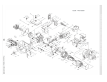
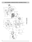
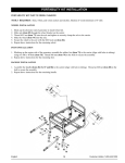
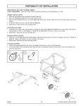
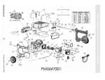
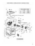
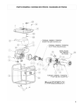
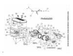
1
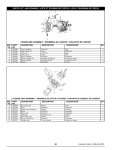
TO ENGINE
AU MOTEUR
AL MOTOR
87
81
85
52
83
86 82
84
7
45
3
43
42
1
79
2
39
40
41 42
53
56
4
59
4
57
60
22
75
73
68
3
61
62
23
65
80
64
38
18
18
25
19
16
30
34
17
19
16
21
17
15
10
32
20
14
19
19
9
29
PARTS DRAWING / SCHEMA DES PIÈCES / DIAGRAMA DE PIEZAS - PM0106500.02
Customer Hotline 1-800-445-1805
PARTS LIST / LISTE DES PIÈCES / LISTA DE PIEZAS - PM0106500.02
REF. PART
NO. NO.
1
2
3
4
7
9
10
14
15
16
17
18
19
20
21
22
23
25
29
30
32
34
38
39
40
41
42
43
45
52
53
56
57
59
60
61
62
64
65
68
73
75
76
80
81
82
83
84
85
86
87
0069005
0068609
0067300
0067301
0067302
0067303
0049365
0067304
0032565
0067787
0067788
0037762.01
0067305
0061990
0069276
0067307
0067308
0068521
0067312
0067313
0067314
0067223
0067316
0067731
0067318
0067319
0069096
0067229
0067230
0067157
0067324
0067325
0067326
0067327
0068610
0067329
0067330
0067331
0067332
0067333
0067334
0067335
0067336
0067405
0068979
0065127
0068982
0068983
0067743
0068978
0069097
DESCRIPTION
Engine 420 cc
Frame
Isolator left
Isolator right
Bracket, air cleaner
Ground terminal
Receptacle L14-30R
Ignition switch
Receptacle L5-30R
Circuit Breaker 20 amp
Circuit Breaker 30 amp
Receptacle 5-20R
Power indicator
Receptacle DC
Hour meter
Panel, wired
Fan
Assy, rotor/stator
Cover, end
Connection board
Voltage regulator
Brush module
Stay, generator
Fuel cap
Washer, fuel cap
Fuel filter
Fuel tank
Fuel gauge
Gasket, fuel gauge
Fuel shut-off
Gasket, exhaust pipe A
Exhaust pipe
Gasket, exhaust pipe
Guard, muffler
Muffler
Shroud, muffler
Rubber seal
Bracket, metal
Side, muffler
Battery
Bracket, battery
Bolt-L
Crosspiece
Rectifier
Valve, rollover
Bushing, rollover valve
Clip, spring 8mm
Clamp, hose 8mm
Hose, fuel
Clamp, hose 12mm
Hose, fuel vapor
DESCRIPTION
DESCRIPCIÓN
Moteur 420 cc
Cadre
Sectionneur gauche
Sectionneur droite
Support
Borne de mise à terre
Prise L14-30R
Interrupteur
Prise L5-30R
Disjoncteurs 20 amp
Disjoncteurs 30 amp
Prise 5-20R
Alimenter l'indicateur
Prise CC
Horomètre
Tableau complet câblé
Ventilateur
Ensemble de rotor et stator
Couvercle
Conseil de connexion
La tension régulatrice
Brosser le module
Séjour
Capuchon
Rondelle
Filtre à carburant
Réservoir de carburant
Jauge de carburant
Joint
Alimenter d’arrêt
Joint A
Tuyau d’échappement
Joint
Garant
Silencieux
Enveloppe
Joint
Support
Côté, silencieux
Batterie
Support
Boulon-L
Pièce en croix
Redresseur
Soupape
Bague
Attache 8mm
Crampon, tuyau 8mm
Flexible
Crampon, tuyau 12mm
Flexible
QTY
Motor 420 cc
Marco
Aislador izquierda
Aislador derecho
Soporte
Terminal, tierra
Receptáculo L14-30R
Interruptor
Receptáculo L5-30R
Cortacircuitos 20 amp
Cortacircuitos 30 amp
Receptáculo 5-20R
Enchufe indicador
Receptáculo CC
Contador Horario
Panel, cabeado completo
Ventilador
Conjunto, rotor y estator
Tapa
Tabla de conexión
El regulador del voltaje
Cepille módulo
Permanezca
Tapa de combustible
Arandela
Filtro de combustible
Tanque de metal de combustible
Indicador de combustible
Empaquetadura
Abastezca de combustible válvula
Empaquetadera A
Tubo de descarga
Empaquetadera
Protector
Silenciador
Guardera
Sello
Soporte
Lado, silenciador
Batería
Soporte
Perno-L
Cruceta
Rectificador
Válvula
Buje
Presilla 8mm
Abrazadera, manguera 8mm
Manguera
Abrazadera, manguera 12mm
Manguera
1
1
2
2
1
1
1
1
1
2
2
2
4
1
1
1
1
1
1
1
1
1
1
1
1
1
1
1
1
1
1
1
1
1
1
1
1
1
1
1
1
2
1
2
1
1
1
1
1
3
1
WARNING: To avoid possible personal injury or equipment damage, a registered electrician or an authorized service representative should
perform installation and all service. Under no circumstances should an unqualified person attempt to wire into a utility circuit.
AVERTISSEMENT: Pour éviter toute blessure personnelle ou dommage à l’équipement, l’installation et tout entretien devralent être effectués par un
électricien qualifié ou un préposé au service autorisé. En aucun cas, une personne non-qualifiée ne devrait essayer de faire le raccord au circuit principal.
ADVERTENCIA: Para evitar posibles lesiones físcas o daños materiales, es necesario que la instalación y todo el servicio sea realizado por un
electricista matriculado o representatnte de servicio autorizado. Bajo ninguna circunstancia debe permitirse que una persona que no está capacitad trate
de manipular cables dentro del circuito de servicio eléctrico.
43
Customer Hotline 1-800-445-1805
3
10
4
12
11
7
17
1
9
2
8
16
6
25
15
5
18
23
22
24
21
20
26
19
27
14
13
ENGINE DRAWING / SCHEMA DE MOTEUR / DIAGRAMA DE MOTOR
44
Customer Hotline 1-800-445-1805
ENGINE PARTS LIST / LISTE DES PIÈCES DU MOTEUR / LISTA DE PIEZAS DEL MOTOR
REF. PART
NO. NO.
1
2
3
4
5
6
7
8
9
10
11
12
13
14
15
16
17
18
19
20
21
22
23
24
25
26
27
0069005
0069075
0068113
0069076
0069077
0068094
0068117
0068118
0068119
0068098
0068094
0068122
0068123
0068124
0068125
0069078
0068105
0068106
0069001
0068130
0069079
0068132
0068133
0068514
0068515
0068516
0068134
0068517
DESCRIPTION
Engine 420 cc
Cylinder head assembly
Gasket, cylinder head
Cover, cylinder head
Gasket, cylinder head cover
Oil seal
Sensor, engine oil
Cover, crankcase
Gasket, crankcase
Oil dipstick
Oil seal
Bolt, valve adjusting
Rocker valve
Engine recoil assembly
Shroud
Carburetor
Gasket, air cleaner
Gasket, carburetor
Air cleaner
Pulley, starter
Fan, flywheel
Flywheel
Coil, ignition
Coil, charge
Clamp, charge coil
Control assembly, choke
Motor, starter
Relay, starter
DESCRIPTION
DESCRIPCIÓN
Moteur 420 cc
Ensemble de tete de cylindre
Joint
Couvercle
Joint
Joint
Détecteur
Couvercle
Joint
Jauge de niveau d'huile
Joint
Boulon
Soupape
Moteur recule l'assemblée
Enveloppe
Carburateur
Joint
Joint
Aérer le nettoyeur
Poulie de démarreur
Ventilateur
Volant-moteur
Bobine d'allumage
Bobine
Collier
L'assemblée de contrôle de buse
Moteur de démarreur
Relais de démarreur
45
QTY
Motor 420 cc
Conjunto de cabezal de cilindro
Empaquetadura
Tapa
Empaquetadura
Sello
Sensor
Tapa
Empaquetadura
Varilla de aceite
Sello
Perno
Válvula
Asamblea de retráctil de motor
Guardera
Carburador
Empaquetadura
Empaquetadura
Limpiador aéreo
Polea de arrancador
Ventilador
Volante
Bobina de encendido
Bobina
Abrazadera
Conjunto de control de ahogador
Motor de arranque
Relevador de arranque
1
1
1
1
1
1
1
1
1
1
1
2
2
1
1
1
1
1
1
1
1
1
1
1
1
1
1
1
Customer Hotline 1-800-445-1805
PORTABILITY KIT INSTALLATION
PORTABILITY KIT PART NUMBER: 0067337
TOOLS REQUIRED: 8mm and 10mm sockets and ratchets, block(s) of wood (minimum of 6” tall).
WHEEL INSTALLATION
1. Blocking up the alternator side of the generator, assemble the axle (item 70) to the carrier (align with holes in channel)
using two M8 bolts. Thread M8 nuts to the bolts to secure the assembly.
2. Slide the wheel (item 69) and washers (item 72) onto the axle, with the offset side of the wheel hub against the carrier.
3. Secure the wheel to the axle with the M10 nut (item 5).
4. Repeat above instructions for the remaining wheel.
FOOT INSTALLATION
1. Assemble the rubber feet (item 76) to the foot bracket (item 67) using M10 nuts (item 5).
2. Blocking up the engine side of the generator, place the foot bracket under the carrier channel. Thread M8 bolts through the
mounting holes and thread M8 nuts to the bolts to secure the foot bracket to the carrier.
HANDLE INSTALLATION
1. Assemble the handle (item 66) to the carrier (align with hole in tubing). Slide M8 x 55 bolt (item 77) through handle,
carrier, and washers (item 78) as shown in diagram and secure with M8 nut (item 6). Tighten until handle is securely
clamped to the carrier.
2. Repeat above instructions for the remaining handle.
English
9
Customer Hotline 1-800-445-1805