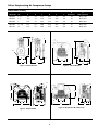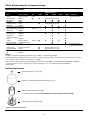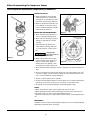
1
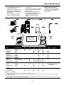
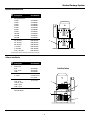
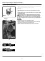
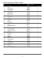
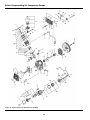
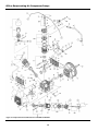
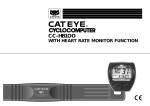
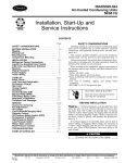
P
U
R
E
A
I
R
T
E
C
H
N
O
L
O
G
Y
Medical Package System
GENERAL PRODUCT MANUAL
Please read and save these instructions. Read carefully before attempting to assemble, install, operate or maintain the product described.
Protect yourself and others by observing all safety information. Failure to comply with instructions could result in personal injury and/or
property damage! Retain instructions for future reference.
Description
The Powerex medical system package is
designed to provide medical breathing
air for hospital and medical institutes.
This system meets NFPA 99
requirements for Level 1 breathing air.
OILLESS OPT/OPS COMPRESSOR
The Powerex oilless reciprocating air
compressor has advanced compressor
technology through the development
of a completely oilless compressor. The
Powerex reciprocating compressor is
provided in duplex, triplex or quadplex
configurations with head unloaders to
provide start, stop or continuous
operation. Composite piston
technology and continuously
lubricating bearings provide oil-free air
reliability for years to come.
RECEIVER TANK
The ASME, National Board registered
air receiver is provided in sizes from
120 to 240 gallons. Each receiver is
rated at 200 PSIG working pressure.
Receivers are provided with sight glass
and moisture drain (manual or
automatic).
CONTROL PANEL
The NEMA 12 control panel is provided
in duplex, triplex or quadplex
configurations and meets NFPA 99
requirements for medical air. Primary
voltage is protected by fusing or circuit
breaker. Control transformer power is
110 volts and protected by secondary
fusing. Pressure control switches signal
the compressors on and off cycle and
signal lag compressor(s) to come on if
air demand increases. A lag, lag
pressure switch or transducer signals a
light and audible alarm warning of a
low pressure condition which is factory
set at 40 PSIG. An acknowledge button
is provided for start condition and
maintenance. The adjustable timer
alternator cycles each compressor so
equal run time is maintained. This
alternator is factory set to alternate
the compressors every 10 minutes. The
exterior of the control panel is
accessible through the door. The panel
disconnects on/off/auto switches run
lights, power on lights, run
hourmeters, lag pressure light, high
ALARM
PANADRY
FLOW
F
DEW/FROST POINT
PPM
CAUTION
AUTO CAL
SAFE
ALARM
ADJ.
SET
ZERO CAL.
CAL. PORT
temperature light and overload reset.
This control panel is UL listed.
DEW POINT MONITOR
The Powerex dew point monitor
provides indication of dew point and
temperature. It’s microprocessor
controlled with user programmable
output range, alarm and calibration.
The NEMA enclosure is protected by a
polymer viewing cover.
CARBON MONOXIDE
MONITOR/ALARM
The carbon monoxide monitor provides
warning to the user of air-supplied
respirators alarming and metering the
presence of carbon monoxide. The
monitor is provided in a NEMA 12
enclosure. In addition to audio/visual
alarm, the meter displays the
concentration of CO in the compressed
air. The meter operates from a 110
VAC supply. Alarm points are set a
10PPM (low) and 20 PPM (high).
AIR COOLED AFTERCOOLER
Four models of beltguard aftercoolers
sized to provide an approach of 20°F.
Constructed of copper tubing and
metal headers for a rugged
construction.
AIR DRYER (REFRIGERATED OR
DESICCANT)
The Powerex air drying system provides
air at 38°F at 100 PSIG for refrigerated
units and -40°F dew point for desiccant
dryer systems. Each system is connected
with bypass capability.
The refrigerated compressed air
dryer(s) are noncycling, direct
expansion type, using R-22 refrigerant,
Powerex • 150 Production Drive • Harrison, OH 45030 • USA
CFC free. A hot gas bypass valve is
provided to maintain 38°F evaporator
temperature. The dryer is selfregulating for large load swings. Heat
exchangers are made of copper tube
construction and insulated.
The regenerative desiccant consists of
two (dual) towers filled with desiccant.
Each tower is switched on and off
stream, alternating the air system
stream and then being regenerated.
Dry purge air pulls moisture from the
desiccant and carries the moisture out
of the air.
MEDICAL FILTER SYSTEM
The medical filter system consists of a
duplex series of filters and pressure
regulators. Air enters the system and is
directed to either bank of filets
controlled by ball valve. The first stage
filter removes solids and liquid
particles. The next stage of filters
remove submicronic particles and
aerosols. The third and final filter is
carbon activated to remove unpleasant
odors. Maximum operating temperature is 125°F and maximum pressure is
150 PSIG.
CONDENSATE DRAIN VALVE
A condensate drain valve must be
installed on any tank. This valve
removes liquid that collects during
compressor operation.
Drain liquid from tank daily.
Safety Guidelines
This manual contains information that is
very important to know and understand.
This information is provided for SAFETY
and to PREVENT EQUIPMENT PROBLEMS.
IN259200AV 11/00
Medical Package System
To help recognize this information,
observe the following symbols.
Danger indicates
an imminently
hazardous situation which, if not
avoided, will result in death or serious
injury.
!
DANGER
Warning indicates
a potentially
hazardous situation which, if not
avoided, could result in death or
serious injury.
! WARNING
Caution indicates a
potentially
hazardous situation which, if not
avoided, MAY result in minor or
moderate injury.
!
CAUTION
Notice indicates
important
information that, if not followed, may
cause damage to equipment.
NOTICE
Unpacking
RECEIVING THE UNIT
Immediately upon receipt of the oilless
compressor, inspect for any damage
which may have occurred during
shipment.
The compressor nameplate should be
checked to verify the correct model
and voltage as ordered.
Do not operate
unit if damaged
during shipping, handling or use.
Damage may result in bursting and
cause injury or property damage.
! WARNING
General Safety Information
The following safety precautions must
be observed at all times:
1. Read all manuals
included with this
MANUAL
product carefully. Be
thoroughly familiar with
the controls and the
proper use of the equipment.
2. Follow all local electrical and safety
codes, as well as in the United
States, the National Electrical Codes
(NEC) and Occupational Safety and
Health Act (OSHA).
3. Only persons well acquainted with
these rules of safe operation should
be allowed to use the equipment.
4. Keep visitors away and NEVER allow
children in the work area.
5. Wear safety glasses and
use hearing protection
when operating the
unit.
6. Do not stand on or use
the unit as a handhold.
7. Before each use, inspect compressed
air system and electrical components
for signs of damage, deterioration,
weakness or leakage. Repair or
replace defective items before
using.
8. Check all fasteners at frequent
intervals for proper tightness.
! WARNING
Electrical equipment and
controls can cause
electrical arcs that will
ignite a flammable gas or
vapor. Never operate or
repair in or near a flammable gas or
vapor. Never store flammable liquids
or gases in the vicinity of the
compressor.
An ASME code
!
safety relief valve,
with a setting no higher than the tank
maximum allowable working pressure,
MUST be installed in the air lines or in
the tank. The ASME safety valve must
have sufficient flow and pressure
ratings to protect the pressurized
components from bursting. The flow
rating can be found in the parts
manual.
WARNING
Do not operate
with pressure
switch or pilot valves set higher than
the tank maximum allowable working
pressure.
!
CAUTION
9. Never attempt to adjust ASME safety
valve. Keep safety valve free from
paint and other accumulations.
!
DANGER
Never attempt to repair or
modify a tank! Welding,
drilling or any other
modification will weaken the tank
resulting in damage from rupture or
explosion. Always replace worn,
cracked or damaged tanks.
NOTICE
Drain liquid from
tank daily.
10. Tanks rust from moisture build-up,
which weakens the tank. Make sure
to drain tank regularly and inspect
periodically for unsafe conditions
such as rust formation and
corrosion.
11. Fast moving air will stir up dust and
debris which may be harmful.
Release air slowly when draining
moisture or depressurizing.
Installation
! WARNING
Disconnect, tag and lock
out power source then
release all pressure from
the system before attempting to
install, service, relocate or perform any
maintenance.
2
Do not lift or move
unit without
appropriately rated equipment. Be sure
the unit is securely attached to lifting
device used. Do not lift unit by holding
onto tubes or coolers. Do not use unit
to lift other attached equipment.
!
CAUTION
Installation of
inlet/outlet air
plumbing from the compressor flange
and eletrical connection must be in
accordance with National Fire
Protection Association (NFPA99) Code
Compliance for Medical Gas Breathing
Air (Level 1).
! WARNING
INSTALLATION SITE
1. The oilless compressor must be
located in a clean, well lit and well
ventilated area.
2. The area should be free of excessive
dust, toxic or flammable gases and
moisture.
3. Never install the compressor where
the surrounding temperature is higher
than 105o F or where humidity is high.
4. Clearance must allow for safe,
effective inspection and
maintenance.
Minimum Clearances
Above
24”
Other sides
36”
5. If necessary, use metal shims or
leveling pads to level the compressor.
Never use wood to shim the
compressor.
VENTILATION
1. If the oilless compressor is located in
a totally enclosed room, an exhaust
fan with access to outside air must be
installed.
2. Never restrict the cooling fan exhaust
air. Maintain a minimum of 3 feet of
clearance around entire unit.
3. Never locate the compressor where hot
exhaust air from other heat generating
units may be pulled into the unit.
WIRING
All electrical hook-ups must be
performed by a qualified electrician.
Installations must be in accordance
with local and national electrical codes.
Use solderless terminals to connect the
electric power source.
PIPING
Refer to the general product manual.
1. Make sure the piping is lined up
without being strained or twisted
when assembling the piping for the
compressor.
2. Appropriate expansion loops or
bends should be installed at the
Medical Package System
compressor to avoid stresses caused
by changes in hot and cold
conditions.
3. Piping supports should be anchored
separately from the compressor to
reduce noise and vibration.
4. Never use any piping smaller than
the compressor connection.
5. Use flexible hose to connect the
outlet of the compressor to the
piping so that the vibration of the
compressor does not transfer to the
piping.
SAFETY VALVES
Tank mounted compressors are
shipped from the factory with safety
valves installed in the tank manifold.
The flow capacity of the safety valve is
equal to or greater than the capacity
of the compressor.
1. The pressure setting of the safety
valve must be no higher than the
maximum working pressure of the
tank.
2. Safety valves should be placed ahead
of any possible blockage point in the
system, i.e. shutoff valve.
3. Avoid connecting the safety valve
with any tubing or piping.
4. Manually operate the safety valve
every six months to avoid sticking or
freezing.
Assembling Modular
Medical System
MODULAR PLACEMENT
1. Unpack each module and discard all
wood shipping materials.
2. Locate frame assembly fasteners
provided in parts pack [includes:
fasteners, filter(s), isolation pads and
inlet flex line].
3. Place modules at location designated
(see picture below for proper
arrangment of modules). Provide
sufficient clearance around unit for
servicing (see minimum clearance
section).
4. Install frame assembly fasteners to
each frame joining the frames
together.
CONNECTING PIPING
1. Locate connection for piping at rear
of unit for compressors module to
receiver tank module.
compressor when temperature is
above 400°F.
3. Connect wiring of unload solenoids
to contacts located on control panel.
The unload solenoid provides loadless
starting of the compressors on off
cycle.
2. Remove plastic caps that protect
piping against contamination.
3. Connect flex joint to frame securely
making sure flex line is not pinched
or chinked.
4. Connect wiring from differential
pressure switch at control panel.
Differential switch wired to contacts
in control panel provided for remote
alarm.
4. Follow steps 1 to 3 for flex line from
dryer package to outlet of receiver
tank.
5. Connect wiring from CO Monitor. A
wire set is provided for power and
the other for alarm. Wiring is
marked for easy attachment.
NOTE: All piping is provided and
sealed for this portion of installation.
5. Locate and attach intake inline air
filter to outside source air or header.
Flex line is provided when attaching
intake of compressors to rigid piping.
6. Connect wiring from Dew Point
Monitor. A wire set is provided for
power and the other for alarm.
Wiring is marked for easy
attachment.
6. Connect outlet souce from filter
package located on dryer module to
outlet source piping.
7. Dryer(s) need a separate properly
protected power supply for each
dryer. Standard voltage is 110 Volts.
Other voltages are available. Check
for voltage of dryer supplied and
current rating provided on data plate
of dryer.
Attach all inlet and
outlet source
piping in accordance with NFPA 99 for
Medical Gas.
! WARNING
ELECTRICAL WIRING OF MODULES
Provide electrical
power in accordance to NEC and local codes. Connection of wiring should be performed by
a qualified electrician.
!
CAUTION
NOTE: Units provided with desiccant
drying systems are wired directly to
the control panel provided.
1. Connect wiring and flex conduit
provided from each motor junction
box to correct hole in bottom of
control panel and starter.
For questions concerning assembling
and start-up, contact Powerex at 1-800544-0350 for technical assistance.
2. Connect each temperature switch
from the compressors to contacts
located in control panel as marked
for each temperature switch.
Temperature switches shutdown the
Operation
Powerex package medical system
operates at a maximum pressure of 100
PSIG. Compressor RPM’s are established
by Powerex based on horsepower and
operating pressure.
MPD Medical
Package System
5. Lift corners of each frame assembly
and install isolation pads provided.
NOTE: Remove shipping brackets
painted orange located at the base
plate of each compressor module.
This will allow spring isolators to free
up reducing noise and vibration of
the unit.
ALARM
PANADRY
FLOW
F
DEW/FROST POINT
PPM
CAUTION
AUTO CAL
SAFE
ALARM
ADJ.
SET
ZERO CAL.
CAL. PORT
3
Medical Package System
BEFORE START UP
1. Make sure all safety warnings, labels
and instructions have been read and
understood before continuing.
2. Remove any shipping materials,
brackets, etc.
3. Confirm that the electric power
source and ground have been firmly
connected.
4. Be sure all pressure connections are
tight.
5. Check to be certain all safety relief
valves, etc., are correctly installed.
6. Check that all fuses, circuit breakers,
etc., are the proper size.
7. Make sure the inlet filter is properly
installed.
8. Confirm that the drain valve is closed.
9. Visually check the rotation of the
compressor pump. If the rotation is
incorrect, have a qualified electrician
correct the motor wiring.
START-UP AND OPERATION
1. Follow all the procedures under
“Before start-up” before attempting
operation of the compressor.
2. Switch the electric source breaker
on.
3. Both dryers should be plugged in
and set at the on position.
4. Dewpoint & CO Monitors should be
on and the sampling valves open.
Calibrate Dewpoint and CO per
enclosed manufacturer’s
instructions.
5. Ensure water lines are properly
installed to water-cooled
aftercoolers. Turn on water.
IMPORTANT: This is not a standard
option. Check to see if water-
cooled aftercoolers were provided.
6. Compressor unit isolation valves are
preset at the factory in the open
position except for tank by-pass
which must remain closed during
normal operation.
7. Dryer and filter isolation valves:
Valves should be open to one dryer
and one filter bank.
8. Close valve leading to the Medical
Air System from receiver on the
compressor unit.
a. Turn both fusible/breaker
disconnects to the on position.
Low pressure alarm will sound.
Silence the alarm by pushing alarm
acknowledge button.
b. Jog each compressor in the manual
position on the selector switch to
check for rotation. (Clockwise if
Medical
Air Schematic
Specifications
Medical Package Duplex – Model MPD
MODEL
SCFM
HP PHASE @ 100
PSIG
SCFM
VOLTAGE
FULL LOAD AMP/ GALLON
MOTOR
TANK
@ 50 PSIG
RPM
870
208 / 230 / 460 17.4 / 16.5 / 8.2
DIMENSION
LxWxH
SHIPPING
WT. (Lbs.)
120
64 x 65 x 76
1288
MPD0508 5(2)
3
33.4
36.2
MPD0758 7.5(2)
3
52.2
55.1
840
208 / 230 / 460
23.4 / 22 / 11
120
64 x 65 x 76
1340
MPD1008 10(2)
3
70
76.3
1070 208 / 230 / 460
29 / 33 / 16.5
200
64 x 65 x 80
1510
MPD1508 15(2)
3
108.4
114.1
1250 208 / 230 / 460
51 / 48 / 24
200
64 x 65 x 80
1630
DIMENSION
LxWxH
SHIPPING
WT. (Lbs.)
Medical Package Triplex – Model MPT
MODEL
SCFM
HP PHASE @ 100
PSIG
MPT0508 5(3)
SCFM
VOLTAGE
FULL LOAD AMP/ GALLON
MOTOR
TANK
@ 50 PSIG
RPM
54.7
870
208 / 230 / 460 17.4 / 16.5 / 8.2
200
96 x 65 x 80
1838
3
50.1
MPT0758 7.5(3)
3
78.8
83.9
840
208 / 230 / 460
23.4 / 22 / 11
200
96 x 65 x 80
1980
MPT1008 10(3)
3
105
111.5
1070 208 / 230 / 460
29 / 33 / 16.5
240
96 x 65 x 92
2160
MPT1508 15(3)
3
162.6
168
1250 208 / 230 / 460
51 / 48 / 24
240
96 x 65 x 92
2280
DIMENSION
LxWxH
SHIPPING
WT. (Lbs.)
128 x 65 x 92
2388
Medical Package Quadplex – Model MPQ
MODEL
SCFM
HP PHASE @ 100
PSIG
SCFM
VOLTAGE
FULL LOAD AMP/ GALLON
MOTOR
TANK
@ 50 PSIG
RPM
870
208 / 230 / 460 17.4 / 16.5 / 8.2
840
MPQ0508 5(4)
3
66.8
74.9
MPQ0758 7.5(4)
3
104.4
120.2
208 / 230 / 460
23.4 / 22 / 11
240
128 x 65 x 92
2490
MPQ1008 10(4)
3
140
153
1070 208 / 230 / 460
29 / 33 / 16.5
240
128 x 65 x 92
2640
MPQ1508 15(4)
3
216.8
221
1250 208 / 230 / 460
51 / 48 / 24
240
128 x 65 x 92
2735
4
240
Medical Package System
facing the black fan shroud and
counterclockwise if facing the
compressor flywheel.)
c. Set both selector switches to the
auto position. Compressors will
both run until the lead pressure
switch closes.
d. Open valve at the air receiver
leading to Medical Air System.
QUADPLEX MPQ
e. Check for air leaks at the
connections.
9. Check that the compressor operates
without excessive vibration, unusual
noises or leaks.
10. Check the discharge pressure. Also
make sure the air pressure rises to the
designated pressure setting by
checking the discharge pressure
gauge.
DUPLEX MPD
DRYER SYSTEM
MDR OR MDD
11. Check the operation of the pressure
switch or the pilot valve for
continuous run units by opening
the stop valve and confirming the
compressor starts or reloads as
pressure drops.
FILTER SYSTEM
MFP
+
+
TRIPLEX MPT
32"
32"
LEFT
END
VIEW
32"
8"
RIGHT
END
VIEW
Consult factory
for special voltages
or arrangements.
COMPRESSOR MAINTENANCE SCHEDULE
Item
Action needed
500
2500
Tank
Inlet air filter
Blower fan
Fan Duct
Compressor Fins
Bearings
Compression rings
Wrist pin bearing
Piston set
V-belt
Safety valve
Pressure gauge
Drain moisture
Replace
Clean
Clean
Clean
Replace
Replace
Regrease
Replace
Inspect, replace
Confirm operation
Inspect
Daily
●
2500
▲
Air leaks
Filters
Inspect
Replace
Moisture drains
traps
Suction pressure
(refrigerated)
Heat exchanger
Inspect
● Inspect
Operating Hours
5000
10,000
(Every 2,500 hrs or less)
●
●
●
●
●
●
(Every 2,500 hrs or less)
●
●
▲
▲
●
*Note 3
15,000
●
●
●
▲
▲
▲
(Every 2,500 hrs or less)
(Every 2,500 hrs or less)
●
▲
▲
●
●
▲
●
▲
20,000
Remarks
●
●
▲
▲
▲
▲
▲
●
▲ (View delta pressure
indication)
●
●
●
●
●
●
●
●
●
●
●
▲ Replace
1. Inspect and perform maintenance periodically according to maintenance schedule.
2. The maintenance schedule relates to the normal operating conditions. If the circumstances and load condition are adverse, shorten the cycle time and do
maintenance accordingly.
3. * The tension of the V-belt should be adjusted during the initial stage and inspected every 1,500 hours afterwards. Proper belt tension for 3/4 to 3 HP units is
12 lbs./.5” deflection; for 5 to 20 HP units, 16 lbs./1.5” deflection
5
Medical Package System
Compressor Parts List
Ref.
No. Description
1
2
3
4
5
6
7
8
9
10
11
12
13
Part Number
Compressor Pump:
5 HP
OPT050
7-1/2 HP
OPT100
10 HP
OPT100
15 HP
OPT150
Corrosion Resistant Vertical Tank
120 Gal.
Consult factory
for number
200 Gal.
Consult factory
for number
240 Gal.
Consult factory
for number
Dew Point Monitor/Probe
Refrigerated
ACO500100
Dessicant
ACO500200
Carbon Monoxide
Monitor/Sensor
ACO600100
Safety Relief Valve
Consult factory
for number
Control Panel
Consult factory
for parts and
availability. Call
1-888-769-7979.
Pressure Gauge
Consult factory
for number
Auto Tank Drain
Electric
ACO100100
Float
ACO100200
Isolation Mounts
Consult factory
for parts and
availability. Call
1-888-769-7979.
Drive Belts
5 HP
BT009900AV
7-1/2 HP
BT011200AV
10 HP
BT009200AV
15 HP
BT010200AV
Pulley (Motor)
5 HP
PU009743AV
7-1/2 HP
PU009775AV
10 HP
PU009716AV
15 HP
PU009758AV
Motor
5 HP
MC022307AV
7-1/2 HP
MC022370AV
10 HP
MC022372AV
15 HP
MC022376AV
Belt Guard Back
5 HP
BG019502AJ
7-1/2 HP
BG218400AV
10 HP
BG218400AV
15 HP
BG218400AV
Belt Guard Front
7-1/2 HP
BG218500AV
10 HP
BG218500AV
15 HP
BG218500AV
Qty.
1
1
1
1
1
1
1
1
1
2
3
1
4
1
1
5
6
1
1
1
2
2
2
2
13
12
11
8
1
1
1
1
10
1
1
1
1
1
1
1
1
1
1
1
6
9
7
Medical Package System
Dryer/Filter Parts List
Ref.
No. Description
1
2
Refrigerated Dryer:
20 CFM
25 CFM
35 CFM
45 CFM
55 CFM
60 CFM
70 CFM
100 CFM
150 CFM
200 CFM
Filter Packages:
1/2”-40 CFM
1/2”-50 CFM
3/4”-60 CFM
1”-70 CFM
1”-100 CFM
1-1/4” -220 CFM
Part Number
ACO200020
ACO200025
ACO300035
ACO000045
ACO200055
ACO200060
ACO200070
ACO200100
ACO200150
ACO200200
2
1
MFP-040-342
MFP-050-342
MFP-060-362
MFP-070-382
MFP-110-382
MFP-220-3A2
See Filter System Manual for details and replacement elements.
Aftercooler/Drain
Ref.
No. Description
1
2
3
4
Aftercooler:
5 HP
7-1/2 -10 HP
15 HP
Drain Trap:
5 - 15 HP
Piping Braided Flex:
5 HP - 1/2 in.
7-1/2 HP - 1/2 in.
10 HP - 3/4 in.
15 HP - 3/4 in.
Temperature Switches
400° N/O Switch
Part Number
ACO700015
ACO700020
ACO700025
Left-End View
Consult factory
for number
Consult factory for
size and length.
1
2
4
3
7
Oilless Oilless Reciprocating Air Compressor Pumps
Please read and save these instructions. Read carefully before attempting to assemble, install, operate or maintain the product described.
Protect yourself and others by observing all safety information. Failure to comply with instructions could result in personal injury and/or property damage! Retain instructions for future reference.
Descriptions
GENERAL
Powerex utilizes cutting-edge compressor technology to provide the most
advanced oilless reciprocating air compressor in the industry. The Powerex reciprocating compressor is available in single and two stage models. Continuously
lubricated, sealed bearings provide oilfree compressed air and long compressor
life. The onboard fan, finned flywheel
and temperature reducing composite
piston create lower operating temperatures.
DRY TYPE INLET FILTER
The inlet filter on the oilless compressor
assures 99% of particulate free air, down
to 10 micron, is admitted to the unit.
Change every 2500 hours or more often
in dirty locations (See Figure 5).
PISTON AND PISTON RINGS
The Powerex oilless reciprocating compressor pistons are made of a highstrength, self-lubricating composite
using the most advanced technology
available. These heat reducing pistons
eliminate the effect of excessive grease
leakage at the wrist pin bearing.
Teflon® rings reduce wear and provide
self lubrication. Piston rings should be
replaced every 10,000 hours of operation (See Figure 12).
!
DANGER
Breathable Air Warning
BEARING REGREASE
The wrist pin bearings of the OPS and
OPT oilless compressors are needle bearings protected by two outer lip seals.
This needle bearing becomes impacted
and requires regreasing at 5,000 hours
(See Figure 15).
BEARING SEALS
The wrist pin bearing lip seals prevent
the lubricating grease from leaking
from the bearing area. The two lip seals
on each connecting rod require replacement every 10,000 hours (See Figure 1622 or page 9).
Installation
This compressor/pump is NOT
equipped and should NOT be used
“as is” to supply breathing quality
air. For any application of air for
human consumption, you must fit
the compressor/pump with suitable
in-line safety and alarm equipment.
This additional equipment is necessary to properly filter and purify
the air to meet minimal specifications for Grade D breathing as
described in Compressed Gas
Association Commodity
Specification G 7.1 - 1966, OSHA 29
CFR 1910. 134, and/or Canadian
Standards Associations (CSA).
DISCLAIMER OF WARRANTIES
In the event the compressor/pump
is used for the purpose of breathing
air application and proper in-line
safety and alarm equipment is not
simultaneously used, existing warranties are void, and Powerex disclaims any liability whatsoever for
any loss, personal injury or damage.
INSTALLATION SITE
1. The oilless compressor must be located in a clean, well lit and well ventilated area.
2. The area should be free of excessive
dust, toxic or flammable gases and
moisture.
3. Never install the compressor where
the ambient temperature is higher
than 105o F or where humidity is high.
Specifications
Model
HP
OPS 010
1
1.5
OPS 030
2
3
OPT 050
Max.
PSIG
145
SCFM @
100 PSIG
RPM
No. of
Cyl.
Flywheel
O.D.
Drive
2.56
11.2
1 GR-A
28
Bore
Stroke
1
2.56
Weight
(lbs.)
3.6
5.3
625
885
145
6.6
10.1
845
1115
2
2.56
2.36
13.8
1 GR-B
53
5
145
17.2
860
2
4.31 x 2.95
3.35
16.9
2 GR-B
110
OPT 100
7.5
10
145
27.5
35.0
855
1090
3
3.54 x 2.95
3.35
18.3
2 GR-B
165
OPT 150
15
145
47.0
1140
3
4.13 x 2.95
3.35
19.6
2 GR-B
170
Powerex • 150 Production Drive • Harrison, OH 45030 • USA
IN258603AV 9/04
Oilless Reciprocating Air Compressor Pumps
4. Clearance must allow for safe, effective inspection and maintenance.
Minimum Clearances
Above
24”
Drive belt side
12”
Other sides
20”
5. If necessary, use metal shims or leveling pads to level the compressor.
Never use wood to shim the
compressor.
VENTILATION
1. If the oilless compressor is located in
a totally enclosed room, an exhaust
fan with access to outside air must be
installed.
sure the flexible hose is rated for
proper pressure and temperature
before installing.
SAFETY VALVES
Tank mounted compressors are shipped
from the factory with safety valves
installed in the tank manifold. The flow
capacity of the safety valve is equal to
or greater than the capacity of the
compressor.
1. The pressure setting of the safety
valve must be no higher than the
maximum working pressure of the
tank.
2. Safety valves should be placed ahead
of any possible blockage point in the
system, i.e. shutoff valve.
BEFORE START UP
1. Make sure all safety warnings, labels
and instructions have been read and
understood before continuing.
2. Remove any shipping materials,
brackets, etc.
3. Confirm that the electric power
source and ground have been firmly
connected.
4. Be sure all pressure connections are
tight.
5. Check to be certain all safety relief
valves, etc., are correctly installed.
6. Check that all fuses, circuit breakers,
etc., are the proper size.
7. Make sure the inlet filter is properly
installed.
2. Never restrict the cooling fan exhaust
air.
3. Avoid connecting the safety valve
with any tubing or piping.
3. Never locate the compressor where hot
exhaust air from other heat generating
units may be pulled into the unit.
4. Manually operate the safety valve
every six months to avoid sticking or
freezing.
9. Visually check the rotation of the
compressor pump. If the rotation is
incorrect, have a qualified electrician
correct the motor wiring.
HOURMETER
START-UP AND OPERATION
1. Follow all the procedures under
“Before start-up” before attempting
operation of the compressor.
WIRING
Refer to the general safety guidelines
manual. All electrical hook-ups must be
performed by a qualified electrician.
Installations must be in accordance
with local and national electrical codes.
Use solderless terminals to connect the
electric power source.
PIPING
Refer to the general safety guidelines
manual.
1. Make sure the piping is lined up
without being strained or twisted
when assembling the piping for the
compressor.
2. Appropriate expansion loops or
bends should be installed at the compressor to avoid stresses caused by
changes in hot and cold conditions.
3. Piping supports should be anchored
separately from the compressor to
reduce noise and vibration.
4. Never use any piping smaller than
the compressor connection.
5. Use flexible hose to connect the outlet of the compressor to the piping so
that the vibration of the compressor
does not transfer to the piping. Make
The hourmeter on the oilless compressor indicates the actual number of
hours the unit has been in operation.
The hourmeter is also used to determine maintenance and service timing.
An hourmeter must be installed
with every oilless compressor.
CONDENSATE DRAIN VALVE
A condensate drain valve must be
installed on any tank to allow removal
of the liquid which will collect during
compressor operation.
NOTICE
Drain liquid from
tank daily.
Operation
Powerex oilless single stage compressors operate at a maximum pressure of
125 PSIG. Two stage compressors operate at a maximum of 145 PSIG and are
equipped for continuous run operation.
Compressor RPM’s are established by
Powerex based on horsepower and
operating pressure.
2
8. Confirm that the drain valve is closed.
2. Switch the electric source breaker on.
3. Open the tank discharge valve completely.
4. Check that the compressor operates
without excessive vibration, unusual
noises or leaks.
5. Close the discharge valve completely.
6. Check the discharge pressure. Also
make sure the air pressure rises to the
designated pressure setting by checking the discharge pressure gauge.
7. Check the operation of the pressure
switch or the pilot valve for continuous run units by opening the stop
valve and confirming the compressor
starts or reloads as pressure drops.
Switch the breaker OFF if the compressor is not to be used for a long period
of time.
These units are
equipped with
head unloaders for continuous run
operation.
NOTICE
Oilless Reciprocating Air Compressor Pumps
Dimensions (inches)
A
B
C
D
E
F
G
(Diameter)
H
(O.D. Flywheel)
Model No.
HP
OPS 010
1 - 11/2
6.7
3.2
11.7
16.2
7.5
4.2
.38
Ø11.2 Ax1
OPS 030
2-3
8.3
3.7
13.4
17.8
18.9
6.4
.43
Ø13.8 Bx1
OPT 050
5
11.4
5.3
18.3
21.9
25.9
7.9
.43
Ø16.9 Bx2
OPT 100
1
7 /2 - 10
12.2
6.3
20.0
21.6
29.7
8.4
.55
Ø18.3 Bx2
OPT 150
15
12.2
6.3
20.0
21.6
29.7
8.4
.55
Ø19.6 Bx2
H
H
D
D
G
A
B
F
A
G
E
C
F
B
C
E
Figure 1 - Model OPS 010
Figure 2 - Model OPS 030
H
H
D
D
G
A
E
B
G
F
A
E
C
Figure 4 - Models OPT 100 and OPT 150
Figure 3 - Model OPT050
3
F
B
C
Oilless Reciprocating Air Compressor Pumps
Maintenance Schedule
Item
Action needed
500
2500
Tank
Inlet Air Filter
Blower Fan
Fan Duct
Compressor Fins
Bearings
Compression Rings
Wrist Pin Bearing
Piston Set
Drain moisture
Replace
Clean
Clean
Clean
Replace
Replace
Regrease
Replace
Daily
Cylinder
Unloader Set
Gasket Set
Bearing Seal Wrist
Pin
V-belt
Pressure Switch
Magnetic Starter
Inspect
Replace
Replace
Replace
Inspect, replace
Confirm operation
Inspect
Operating Hours
5000
10,000
20,000
Remarks
Drain tank daily
(Every 2,500 hrs or less)
(Every 2,500 hrs or less)
*Note 4
*Note 3
15,000
Replace if contact
points deteriorated
Safety Valve
Confirm operation
(Every 2,500 hrs or less)
Pressure Gauge
Inspect
(Every 2,500 hrs or less)
Inspect
Replace
NOTES:
1. Inspect and perform maintenance periodically according to maintenance schedule.
2. The maintenance schedule relates to the normal operating conditions. If the circumstances and load condition are adverse,
shorten the cycle time and do maintenance accordingly.
3. The tension of the V-belt should be adjusted during the initial stage (500H) and inspected every 2,500 hours afterwards.
Proper belt tension for 1 to 3 HP units is 2-3 lbs./.5” deflection; for 5 to 15 HP units, 4-6 lbs./.5” deflection.
4. See page 8.
Air Filter Replacement
1. Remove wing nut or spring clips
2. Remove canister and wipe inside clean with dry cloth.
3. Remove and discard filter cartridge.
4. Install new filter cartridge. Do not attempt to clean and reuse filter cartridge.
5. Wipe inside clean with dry cloth.
Figure 5 - Air Filter Replacement
4
Oilless Reciprocating Air Compressor Pumps
Valve Inspection/ Replacement (Inspect Every 5,000 Hours)
INSPECT VALVE SET
1. Remove head bolts from cylinder
head. Head bolts for some models
are used also as cylinder bolts, which
penetrates crankcase (See Figure 7).
2. Remove cylinder head and valve set.
If it is difficult to remove by hand,
insert screwdriver between cylinder
and valve set and remove.
INSPECTION AND MAINTENANCE
Figure 7
1. Check if exhaust valve (A) sticks to
seat or is damaged (See Figure 8).
Check for peeling
or wear (C)
2. Check if there is breakage, gouge or
damage to appearance of intake
valve (B).
(B)
3. Lift intake valve by 10 mm and
check if there is peeling and wear
on coating surface of valve spacer
(C).
Lifting intake
valve too much can
cause damage to intake valve.
!
Figure 6
CAUTION
4. Replace with intake valve if valve
plate and valve spacer are worn or
wear is over 0.5 mm in depth. If
exhaust valve rises upwards, clean
seat surface if foreign matter sticks.
(A)
(A)
Figure 8
5. Clean the whole valve set taking care not to damage, seat surface and remove
dust.
6. If viton seals (upper and lower) reach inspection time, replace them. Even if its
not time to inspect, be sure to replace if they do not protrude from groove for
seal or seal has hardened or been damaged.
7. Be sure to replace plastic seat in cylinder.
8. Fit valve set while paying attention to black plastic seat of intake valve fitted to
cylinder (so that you do not drop seat or insert tip of valve under seat).
9. Fit cylinder cover and tighten fitting bolt with designated torque.
NOTES:
• When using valve set again, replace upper and lower viton seals.
• When replacing valve set, replace with upper and lower viton seals (valve set
with packing set). You cannot reuse disassembled valve set.
We are not responsible for any problems caused by reuse of disassembled valve
set.
REASSEMBLY
Assemble in reverse order of disassembling. Tighten each section with designated
tightening torque (See Chart on page 6).
5
Oilless Reciprocating Air Compressor Pumps
Cylinder Inspection/Replacement
1. Remove cylinder head and valve set. Pay attention not to lose semicircular
(black plastic) seat inserted at top surface of cylinder.
INSPECTION
1. Surface treated layer is worn and metal is exposed. Replace worn piston
and piston ring.
2. Scuffing (damage) due to foreign matter. Replace if it is swollen by scuffing
the aluminum cylinder.
3. Replace if several vertical scratches are side by side at a narrow distance.
Figure 9
NOTE: Blackish streaks you can feel with your nail or finger are not damage
but sliding marks of piston and piston ring. You do not need to replace the
piston set or cylinder even if there are several marks on the whole diameter of
the cylinder.
Replace if it
is scratched
Seat
REASSEMBLY
1. Assemble in reverse order of disassembling cylinder.
2. Direction of cylinder is set so that semicircular spot facing, to which seat
(black plastic) is inserted, faces toward flywheel side.
3. Tighten cylinder bolt with designated torque (refer to chart below).
Figure 10
Cylinder
Cylinder Bolt Torque
OPS010
OPS030
OPT050, OPT150
OPT100
156 in. lb.
295 in. lb.
Head Bolt Torque
OPS010, OPS030, OPT050,
OPT100, OPT150
156 in. lb.
6
Oilless Reciprocating Air Compressor Pumps
INSPECT PISTON AND PISTON RING (INSPECT EVERY 5,000 HOURS)
1. Remove cylinder head and cylinder.
2. Do not use tool to remove the ring.
NOTE: Expanding ring too much and deforming can cause wear and leakage.
(See Figure 12). Mark upper surface (not lower surface) of removed ring for
easy distinction.
3. Inspect lower surface (A) and outer side surface (B) of ring (See Figure 13).
Measure thickness (C) of ring with calipers. Replace if foreign matter enters
(A, B) or deep damage is found or (C) dimension is less than 2.5 mm at any
point around the rings circumference.
Figure 11
NOTE: Clean the whole ring and ring groove with soft clean cloth.
!
CAUTION
Ring and piston dust build up in the ring groove can
cause knocking. This is sometimes mistaken for bad valve
or bearing.
REASSEMBLE: Pay attention to the fit of the piston and wrist pin fit. There
should be no axial play or looseness in the wrist pin area.
NOTE: Do not separate piston from connecting rod when inspecting piston
or ring. If you remove piston from connecting rod, you may damage oil seal
of connecting rod and needle bearing.
PISTON REPLACEMENT
1. Inspect for appearance if there is deep damage or crack on top of piston or
at pin boss.
2. Remove piston ring and inspect for breakage or droop of ring land.
Figure 12
3. Remove o-rings on both sides of piston pin.
4. Push piston pin to one side.
(B)
(A)
NOTE: Install bearing retention sleeve in grease kit/piston set. The retention
sleeve is to prevent the needle bearing from falling out of the bearing area.
On the HP cylinder only.
5. Remove piston pin.
(C)
Figure 13
Piston rings
O-ring
Piston
Piston pin
Figure 14
7
Oilless Reciprocating Air Compressor Pumps
PISTON ORIENTATION CHART FOR OILLESS OPS/OPT SERIES
Pump
Compressor
Model
OPS010
Bore
No.
Cylinders
No. of Piston
Rings per
Piston
65 mm
1
1
Mark on
Top of
Piston
Flywheel side
Fan side
Flywheel side
OPS030
65 mm
1
1
LP 105 mm
1
1
HP 75 mm
1
2
Fan side
Flywheel side
OPT050
LP 90 mm
2
1
HP 75 mm
1
2
Fan side
Flywheel side
OPT100
LP105
2
1
HP75
1
2
Fan side
Flywheel side
OPT150
Fan side
NOTE: The orientation in which the pistons are reinstalled is very important. Improper placement will cause premature wear of the ring and piston.
Small end of
connecting rod
NOTE: When removing HP piston on two-stage pumps, remove piston and
then insert retention sleeve having the same diameter of piston pin or piston to small end of connecting rod. If not, you may drop or lose needles
from the bearing, as HP needle bearing does not have support.
!
CAUTION
Fit piston by referring to ∆ marking on the top of the
piston surface and list on above chart.
NOTE: Gradually insert piston pin while turning it. Inserting with force can
damage oil seal of needle bearing.
Piston Pin
Jig (fixture) or
collar
Powerex Oilless
Reciprocating
Grease
6 Grams
#IP634500AV
Figure 15
P
U
R
Oilless
E
A
I
R
T
E
C
H
N
O
L
O
G
Y
Reciproc
Grease ating
6 Grams
#IP634
500AV
8
* FOR LOW PRESSURE PISTON ONLY
Oilless Reciprocating Air Compressor Pumps
WRIST PIN BEARING SEAL REPLACEMENT (REPLACE EVERY 10,000 HOURS)
Replacing Oil Seal
Figure 16
1. Insert the plastic retention sleeve
which protects the needle bearing
from dropping out.
Figure 17
Figure 18
2. Remove the two oil seals by using a
screwdriver.
3. Clean both surfaces where oil seals
are removed.
Pushing
Board
Figure 19
4. Push the oil seal into the small bearing end horizontally.
Figure 21
7. Apply a small volume of adhesive at
several points.
Figure 20
5. Press the oil seal with a C-clamp into
the small bearing end.
6. Repeat on opposite side.
Figure 22
8. Remove the retention sleeve inserted
at the first step.
NOTE: You may use a “C” clamp or two large washers and bolt with nut through the bearing. Then apply pressure to install
the seals. This makes it easy to replace the seals without removing the crankshaft.
9
Oilless Reciprocating Air Compressor Pumps
Inspect Connecting Rod, Wrist Pin and Crankshaft
REPLACE CONNECTING ROD SET AND CRANKSHAFT AS A SET
Pressing bearing into connecting rod and connecting rod set into crankshaft
requires special fixtures. Without such fixtures, the squareness and parallelism of each part will be affected.
Shaft
fan side
DISASSEMBLE AND REMOVE CYLINDER COVER, CYLINDER AND PISTON
IN THIS ORDER
1. Bearing at large end of connecting rod: Replace if it does not move or
feels stuck holding and moving small end of connecting rod.
2. Bearing of crankshaft: Replace if you feel some resistance when slowly
turning shaft.
3. Bearing at wrist pin: Check for breakage of needle bearing and damage of
cage.
DISASSEMBLING: CRANKSHAFT SET
1. Disassemble cylinder head, cylinder and piston.
2. Remove bolts from bearing cap and remove bearing cap.
Figure 23
3. Lightly tap shaft fan side with non-shock hammer (avoid metal hammer)
and remove crankshaft. After bearing leaves the crankcase bore, pull connecting rod out as illustrated and remove it from crankcase (See Figure 23).
REASSEMBLY
1. Heat bearing housing of crankcase with industrial dryer or simple burner
just the same as disassembling.
2. Insert crankshaft set into crankcase in reverse order of disassembling and
insert bearing into housing.
3. Tap shaft from pulley side with non-shock hammer and insert it inwards.
4. Fit bearing case. Grease bearing housing of bearing case.
10
Oilless Reciprocating Air Compressor Pumps
Notes
11
Oilless Reciprocating Air Compressor Pumps
Figure 24 - Replacement Parts Illustration for OPS010
12
Oilless Reciprocating Air Compressor Pumps
Ref.
No.
Description
Part Number for model
OPS010
1
6
16
18
24
27
33
34
35
36
47
50
51
52
57
62
65
67
67-1
72
72-1
84
99
121
197
200
500
600
Cylinder
Cylinder head
Elbow (Unloader)
Unloader cap
Spring guide set
Bolt (cylinder head)
Bolt (cylinder)
Bolt (bearing cap)
Crankcase
Bearing cap
O-ring
Crank shaft
Flywheel pulley
Parallel pin
Ball bearing (bearing cap)
Hex blot (fan, flywheel)
Connecting rod w/bearings
Piston set
Piston ring
Intake filter set
Intake filter
Screw (dust cover)
Seat (intake valve)
Dust cover
Lip seals wrist pin
Unloader set
Gasket set
Valve set with gasket
Crank shaft set (Includes 50, 57 and 65)
91000560
91002630
06800261
01052041
91932560
06137835
06137825
06137620
91100630
91101630
01146550
91201551
01271550
06992857
91903640
91237640
91906630
91348550
06131508
01301560
91383630
97191000
91931560
91936640
91933640
91918630
13
Qty
1
1
1
1
1
4
8
8
1
1
1
1
1
1
2
1
1
1
1
1
1
2
1
1
2
1
1
1
1
Oilless Reciprocating Air Compressor Pumps
Figure 25 - Replacement Parts Illustration for OPS030
14
Oilless Reciprocating Air Compressor Pumps
Ref.
No.
1
6
16
17
20
21
24
27
30
31
33
34
35
36
38
47
50
51
52
53
57
58
59
60
61
64
65
67
67-1
72
72-1
78
79
82
87
99
109
193
195
196
197
200
500
600
Description
Part Number for model
OPS030
Cylinder
Cylinder head
Elbow (unloader)
Tee union assembly
Intake joint (1)
Intake joint (2)
Spring guide set
Bolt (cylinder head)
Flange (breather)
Bolt
Bolt (cylinder)
Bolt (bearing cap)
Crank case
Bearing cap
Filter (crank case)
O-ring
Crank shaft
Flywheel pulley
Woodruff key
Hex nut
Ball bearing (bearing cap)
Ball bearing (crank case)
Fan
Cover (fan)
Hex bolt (fan, flywheel)
Liner (connecting rod)
Connecting rod w/bearing
Piston set
Piston ring
Intake filter set
Intake filter
O-ring
Intake pipe
Screw (filter)
Tube
Seat (intake valve)
O-ring (intake joint)
Fan guard
Bolt (intake joint 1)
Bolt (intake joint 2)
Lip seals wrist pin
Unloader set
Gasket set
Valve set with gasket
Crankshaft set (includes part #’s 50, 57, 58 and 65)
91000560
91002640
06800261
06803261
91345561
91346571
91932560
06137835
91176660
06995831
06137825
06137620
91100640
91101560
91348690
01146560
91202560
06600013
06994016
91220560
91134560
06992857
01480640
91903640
91237640
91907570
91353660
06630032
91407560
06131508
01909400
01301560
06639906
91135560
01095570
01095560
97191000
91931560
91936640
91933640
91918640
15
Qty
2
2
1
1
1
1
2
8
1
20
8
8
1
1
1
1
1
1
1
2
1
1
1
1
2
1
2
2
2
1
1
2
1
2
1
2
2
2
1
1
4
2
2
2
1
Oilless Reciprocating Air Compressor Pumps
197
197
Figure 26 - Replacement Parts Illustration for OPT050
16
Oilless Reciprocating Air Compressor Pumps
Ref.
No.
1
2
3
6
7
14
17
18
20
24
27
30
31
33
34
35
36
38
47
50
51
52
53
54
57
58
59
60
61
64
65
66
67
67-1
68
68-1
68-2
72
72-1
82
87
99
108
109
110
120
143
Description
Part Number
for model
OPT050
Qty
Cylinder (LP)
Cylinder (HP)
Liner
Cylinder Head (LP)
Cylinder Head (HP)
Elbow (Intercooler)
Tee Union Ass’y
Unloader Cap
Intake Joint
Spring Guide Set
Bolt (Cylinder Head)
Flange (Breather)
Bolt (Unloader Cap)
Bolt (Cylinder)
Bolt (Bearing Cap)
Crank Case
Bearing Cap
Filter (Crank Case)
O-ring
Crank Shaft
Flywheel Pulley
Woodruff Key
Hex Nut
Washer
Ball Bearing (Brg. Cap)
Ball Bearing (Crank Case)
Fan
Cover (Fan)
Hex Bolt (Fan, Flywheel)
Liner (Connecting Rod)
Connecting Rod Set
Connecting Rod Set
Piston Set (LP)
Piston Ring (LP)
Piston Set (HP)
Piston Ring (HP)
Wrist Pin (Prepacked)
Intake Filter Set
Intake Filter
Screw (Filter)
Unloader Tube
Seat (Intake Valve)
Intercooler Flange
O-ring (Intake joint)
Connecting Pipe
Bolt (Intercooler)
O-Ring (Connecting Pipe)
91000680
91947680
91177680
91002691
91002680
01415690
06803261
01052451
91345660
91949694
06137850
91176660
06995831
06137130
06137830
91100660
91101580
91348690
01146430
91201660
06600016
06994016
06991512
91220690
91134660
06992817
91472690
91903680
91236681
91910670
91930680
91924680
91907660
91353660
06235304
91420660
01301691
91403690
06639906
91400660
01435692
06632825
Ref.
No.
145
157
165
171
173
174
175
176
193
196
197
200
500
550
600
650
1
1
2
1
1
2
2
2
1
2
10
1
26
8
10
1
1
1
1
1
1
1
4
1
1
1
1
1
2
1
1
1
1
1
1
2
1
1
1
2
1
2
1
2
1
2
1
17
Description
O-Ring (Connecting Pipe)
Hex. Bolt (Intercooler)
Nut (Intercooler)
Connecting Pipe Set
Intercooler
Intercooler Flange (1)
Intercooler Flange (2)
Gasket (Intercooler)
Fan Guard
Bolt (Intake Joint)
Lip seals wrist pin
Unloader Set
Gasket Set (LP)
Gasket Set (HP)
Valve Set with Gasket (LP)
Valve Set with Gasket (HP)
Crank Shaft Set (50, 57, 58, 65, 66)
Part Number
for model
OPT050
Qty
06632835
06996460
06994015
91914661
91404690
91405690
91406690
01432690
91144660
01344690
97191000
91932681
91936680
91937681
91933681
91934683
91918660
1
6
6
1
2
1
1
3
2
2
4
2
1
1
1
1
1
Oilless Reciprocating Air Compressor Pumps
172
197
197
171
Figure 27 - Replacement Parts Illustration for OPT100 and OPT150
18
Oilless Reciprocating Air Compressor Pumps
Ref.
No.
1
2
6
7
14
17
17-1
18
20
21
24
27
31
33
34
35
36
38
47
50
51
52
53
54
57
58
59
60
61
62
63
65
66
67
67-1
68
68-1
68-2
72
72-1
78
79
82
87
96
99
108
109
110
120
131
143
145
157
165
171
172
173
174
175
176
193
195
196
197
200
500
550
600
650
Part Numbers For Models
Description
OPT100
OPT150
Cylinder (LP)
Cylinder (HP)
Cylinder head (LP)
Cylinder head (HP)
Elbow (Intercooler)
Tee union assembly
Elbow union assembly
Unloader cap
Intake joint (1)
Intake joint (2)
Spring guide set
Bolt (Cylinder head)
Bolt (Unloader cap)
Bolt (Cylinder)
Bolt (Bearing cap)
Crank case
Bearing cap
Filter (Crank case)
O-ring (Bearing cap)
Crank shaft
Flywheel pulley
Woodruff key
Hex nut
Washer (Intercooler)
Ball bearing (Bearing cap)
Ball bearing (Crank case)
Fan
Fan cover
Hexagon bolt (Fan)
Hexagon bolt (Flywheel)
Hexagon nut (Intake joint)
Connecting rod (LP)
Connecting rod (HP)
Piston set (LP)
Piston ring (LP)
Piston set (HP)
Piston ring (HP)
Wrist pin set (prepacked)
Intake filter set
Intake filter
O-ring (Intake pipe)
Inlet pipe
Bolt (Crankcase filter)
Unloader tube
Unloader tube
Wear pad, valve
Intercooler Joint
O-ring ( Intercooler Joint )
Connecting Pipe
Bolt ( Intercooler)
Cover Bracket
O-ring ( Connecting Pipe )
O-ring ( Connecting Pipe )
Hex bolt ( Intercooler )
Nut ( Intercooler )
Connecting Pipe Set ( 1 )
Connecting Pipe Set ( 2 )
Intercooler
Intercooler Flange ( 1 )
Intercooler Flange ( 2 )
Gasket ( Intercooler )
Fan Guard
Bolt ( Intake Joint 1 )
Bolt ( Intake Joint 2 )
Lip seals wrist pin
Unloader Set
Gasket Set ( LP )
Gasket Set ( HP )
Valve Set with Gasket ( LP )
Valve Set with Gasket ( HP )
Crank shaft set (Includes 50, 57, 58, 65 & 66)
91000670
91947680
91002691
91002680
01415690
IP010400AV
96800261
01052451
01345691
01346690
91949694
06137850
06995831
06137130
06137830
91100680
91101690
91348690
01146690
91000680
91947680
91002691
91002680
01415690
IP010400AV
96800261
01052451
01345691
01346690
91949694
06137850
06995831
06137130
06137830
91100680
91101690
91348690
01146690
01201590
06600016
06994016
06991512
91201690
06600016
06994016
06991512
91220690
91134690
06992817
06992833
06382086
91903670
91236671
91910670
91930680
91924680
91907590
91353690
06630032
01407690
06131508
01420690
01419600
01301691
91403690
06639906
91402680
01435692
01413690
06632825
06632835
06996460
06994015
01914590
01915590
91404690
91405690
91406690
01432690
01135690
01343690
01344690
97191000
91932681
91936670
91937681
91934691
91934683
91917680
19
91220690
91134690
06992817
06992833
06382086
91903680
91236681
91910670
91930680
91924680
91907690
91353690
06630032
01407690
06131508
01420690
01419600
01301691
91403690
06639906
91402680
01435692
01413690
06632825
06632835
06996460
06994015
01914690
01915690
91404690
91405690
91406690
01432690
01135690
01343690
01344690
97191000
91932681
91936680
91937681
91933681
91934683
91917680
Qty
2
1
2
1
4
2
1
3
1
1
3
16
30
12
10
1
1
1
1
1
1
1
6
1
1
1
1
1
1
1
1
2
1
2
2
1
2
1
1
1
2
1
4
1
1
3
1
3
1
4
2
2
1
6
6
1
1
4
2
2
6
2
1
2
6
3
2
1
2
1
1
Oilless Reciprocating Air Compressor Pumps
Powerex Limited Warranty
POWEREX 3 YEAR / 10,000 HOUR EXTENDED PARTS LIMITED WARRANTY - Powerex warrants each Compressor Pump or
Scroll Air-End against defects in material or workmanship from the date of purchase for a period of Three years or
10,000 hours, whichever may occur first. This warranty applies to the exchange of part(s) of the compressor pump or
air-end found to be defective by an Authorized Powerex Service Center.
POWEREX 1 YEAR / 5,000 HOUR INLET TO OUTLET LIMITED WARRANTY - Powerex warrants each Compressor Unit,
System, Pump, or Air-End against defects in material or workmanship from the date of purchase for a period of One
Year or 5,000 Hours, whichever may occur first. This warranty applies to the exchange of defective component part(s)
and labor performed by an Authorized Powerex Service Center.
Coverage. The above mentioned warranty applies to Powerex manufactured units or systems only. Items
listed in the operator’s manual under routine maintenance are not covered by this or any other warranty.
Failure to complete maintenance as stated in the maintenance schedule will void this warranty.
THERE IS NO OTHER EXPRESS WARRANTY. IMPLIED WARRANTIES, INCLUDING THOSE OF MERCHANTABILITY AND FITNESS FOR A PARTICULAR PURPOSE, ARE LIMITED TO ONE YEAR FROM THE
DATE OF PURCHASE: AND TO THE EXTENT PERMITTED BY LAW, ANY AND ALL IMPLIED WARRANTIES ARE EXCLUDED. THIS IS THE EXCLUSIVE REMEDY AND LIABILITY FOR CONSEQUENTIAL
DAMAGES UNDER ANY AND ALL WARRANTIES IS EXCLUDED TO THE EXTENT EXCLUSION IS PERMITTED BY LAW.
Limitation of Liability. To the extent allowable under applicable law, Powerex’s liability for consequential
and incidental damages is expressly disclaimed. Powerex’s liability in all events is limited to, and shall not
exceed, the purchase price paid.
Warranty Disclaimer. Powerex has made a diligent effort to illustrate and describe the products in this literature accurately; however, such illustrations and descriptions are for the sole purpose of identification,
and do not express or imply a warranty that the products are merchantable, or fit for a particular purpose,
or that the products will necessarily conform to the illustrations or descriptions.
Product Suitability. Many jurisdictions have codes and regulations governing sales, construction, installation, and/or use of products for certain purposes, which may vary from those in neighboring areas. While
Powerex attempts to assure that its products comply with such codes, it cannot guarantee compliance, and
cannot be responsible for how the product is installed or used. Before purchase and use of a product,
please review the product applications,and national and local codes and regulations, and be sure that the
product, installation, and use will comply with them.
Claims. Claims pertaining to the merchandise in this schedule, with the exception of warranty claims, must
be filed with POWEREX within 6 months of the invoice date, or they will not be honored. Prices, discounts
and terms are subject to change without notice or as stipulated in specific product quotations. All agreements are contingent upon strikes, accidents, or other causes beyond our control. All shipments are carefully inspected and counted before leaving the factory. Please inspect carefully any receipt of merchandise
noting any discrepancy or damage on the carrier’s freight bill at the time of delivery. Discrepancies or damage which obviously occurred in transit are the carrier’s responsibility and related claims should be made
promptly directly to the carrier. Returned merchandise will not be accepted without prior written authorization by POWEREX and deductions from invoices for shortage or damage claims will not be allowed.
UNLESS OTHERWISE AGREED TO IN WRITING, THESE TERMS AND CONDITIONS WILL CONTROL IN
ANY TRANSACTION WITH POWEREX any different or conflicting terms as may appear on any order form
now or later submitted by the buyer. All orders are subject to acceptance by POWEREX.