1
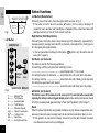
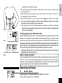
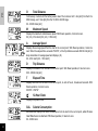
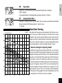
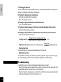
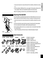
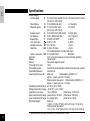
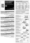
®
®
CC-HB1OO
WITH HEART RATE MONITOR FUNCTION
E
Introduction
Thank you for purchasing CATEYE CYCLOCOMPUTER Model CC-HB100. As well
as cyclocomputer functions, this model has heart rate monitor functions, which enables safe and scientific training, by monitoring heart rate with a Wireless Heart Rate
Sensor. Double pulse wireless heart rate transmission helps prevent interference
caused by shocks and outer noises, offering the most accurate measuring. In addition
to functioning as a cyclocomputer, it can be used as a heart rate monitor for other noncycling exercise programs. The features are as follows:
Heart Rate Monitor Functions:
* Measures current heart rate with a Wireless Heart Rate Sensor.
* Gives target zone training by setting upper/lower heart rate limits, with flashing
alarm symbols.
* Measures average heart rate in conjunction with the elapsed time of riding.
* Estimates and totals calorie consumption calculated from the heart rate.
Cyclocomputer Functions:
•
•
•
•
•
•
•
*
Current speed
Maximum speed
Average speed
Total distance
Trip distance
Elapsed time
Clock time
Auto (Automatic start/stop) function.
Before operating, thoroughly familiarize yourself with this manual so that you understand the functions completely. Keep this manual along with the warranty card for
future reference.
2
Index
Names --------------------------------------------------------------------------------------------------- 4
For Safe Operations --------------------------------------------------------------------------------- 5
Button Functions -------------------------------------------------------------------------------------- 6
How to Use as a Cyclocomputer
1. Main Unit Preparation ----------------------------------------------------------------- 7
2. Mounting to Bicycle -------------------------------------------------------------------- 8
3. Auto (Automatic Start/Stop) Function --------------------------------------------- 9
4. Power Saving Function --------------------------------------------------------------- 9
How to Use as a Heart Rate Monitor
1. Wireless Heart Rate Sensor -------------------------------------------------------- 10
2. Before Attaching ----------------------------------------------------------------------- 10
3. Attaching Wireless Heart Rate Sensor ------------------------------------------ 10
4. Setting Upper/Lower Heart Rate Limit ------------------------------------------- 11
Measuring and Display ----------------------------------------------------------------------------- 11
Heart Rate Training --------------------------------------------------------------------------------- 13
Troubleshooting -------------------------------------------------------------------------------------- 14
Replacing Battery
1. Main Unit -------------------------------------------------------------------------------- 16
2. Wireless Heart Rate Sensor -------------------------------------------------------- 16
Replacing Electrode Belt -------------------------------------------------------------------------- 17
Spare Accessories ---------------------------------------------------------------------------------- 17
Specifications ----------------------------------------------------------------------------------------- 18
Limited Warranty ------------------------------------------------------------------------------------ 19
Setting Values Cross Reference Table --------------------------------------------------------- 19
E
3
E
Names
Main Unit
C
5 1 4
A
Display
1. Heart Rate Display
2. Speed Display
3. Sub Display
A
4. Heart Rate Symbol
5. Alarm Symbol of Upper/Lower Heart Rate Limit
6. Mode Symbol
7. Speed Scale Symbol
D
E
8. Wheel Sensor Signal Symbol
9. Auto (Automatic Start/Stop) Mode Symbol
B Battery Cover
C Contact
D Mode Button
Wireless Heart Rate Sensor
E Start/Stop Button
H Transmitter
F AC (All Clear) Button
H
I Electrode Belt
G Set Button
J Attachment Belt
4
Bracket
Wire
Sensor
Sensor Band A (Large/Small)
Sensor Band B
Sensor Screw
Magnet
Sensor Band Rubber Pad
Bracket Rubber Pad (2 pcs.)
Wire Securing Tape
F
7
B
8 6
3
9
G
C
I
Accessories/Attachments
K
L
M
N
O
P
Q
R
S
T
2
J
I
T
Q
P
R
L
K
M
N
O
S
For Safe Operations
For safe and appropriate use, always observe the following.
WARNING
• If you are a pacemaker user, never use this.
• Don't use this model in an airplane.
• In case your skin reacts with the Wireless Heart Rate Sensor and presents a sign of rash
or eruption, refrain from frequent use.
• Don't pay too much attention to your cyclocomputer functions when riding. Keep your eyes
on the road and give due consideration to safe riding.
E
FOR BEST OPERATIONS
Wireless Heart Rate Sensor
• In the following places, strong electromagnetic wave will interfere correct measuring:
1. Places near television sets, radios, motors/engines, or in an automobile/railroad car
2. A railroad crossing, near railway lines, television transmitting station, radar base
• Don't place more than two transmitters within the radius of 1.5 meters of the main unit. Avoid using this
unit together with other cordless devices at the same time.
• Don't drop or impact the main unit/transmitter.
• Always keep the Wireless Heart Rate Sensor clean by wiping off sweat with mild soap.
• Don't bend, twist or pull hard at the electrode belt.
• The electrode belt is expendable. It may deteriorate and present function error after a long term use.
Replace with a new one when you notice a sign of deterioration.
Main Unit
• Don't leave the main unit exposed to direct sunlight for extended periods of time.
• Never disassemble the main unit.
• Check relative position of sensor and magnet periodically.
• When using this unit as an independent heart rate monitor apart from bicycle, switch off the Auto (automatic start/stop) function and use the right button for operation.
• If the space between the buttons and the body becoming clogged with mud or sand, it will hinder button
operation. Wash it off softly with water.
• When the contact gets wet, dry it off with cloth; rust will cause function error.
• For cleaning, use mild soap, and wipe dry with a soft cloth. Never apply paint thinner, benzine or alcohol
to the computer. Damage will result.
• Maximum transmission for the Wireless Heart Rate Sensor is about 80 cm.
5
Button Functions
E
MODE START/STOP
Fig.1
Left Button (Mode Button)
With each press of this button, the mode symbol shifts as shown in Fig. 2.
* If this button is held for about 2 seconds,
symbol (12-hour clock) is displayed. If
pressed for over 4 seconds, heart rate display is changed from the current heart rate to AP
(average heart rate) or from AP to the current heart rate.
Right Button (Start/Stop Button)
Left Button
With each press, this button starts or stops measuring of trip distance(D), elapsed time(T),
average speed(A), average heart rate(AP), and calorie consumption(CAL). During operation, the speed scale symbol flashes.
symbol is on], this button does not
* In the Auto (automatic start/stop) function [when
work (refer to page 9).
SUB DISPLAY
T
D
A
O
M
HR
AP
Hold down
2 sec.
4 sec.
CAL
Fig.2
HEART RATE DISPLAY
T ---------D ---------A ---------O ---------M --------CAL ----------HR -------AP -------6
Elapsed Time
Trip Distance
Average Speed
Total Distance
Maximum Speed
Calorie Consumption
12-Hour Clock
Heart Rate
Average Heart Rate
Set Button (on the back)
This button is used for the following operations:
For switching on/off the Auto (automatic start/stop) function
------------------------------------------------------ press this button in T, D or A mode
For setting the wheel circumference ------ press this button in O mode (but in stop state)
display (but in stop state)
For setting clock time -------------------------- press this button in
For setting the upper/lower heart rate limit
------------------------------------------------------ press this button in M mode (but in stop state)
AC Button (on the back)
This button erases all the data stored in memory. Don't press this button except after
replacing the battery or when irregular display occurs. Since all the memories are cleared
off, set the necessary data again according to "Main Unit Preparation" (refer to page 7).
Reset
When the left and right buttons are pressed simultaneously, trip distance, elapsed time, average speed, maximum speed, average heart rate and calorie consumption returns to zero.
* If this operation is executed in O display, it doesn't reset the data; instead, the wheel
circumference stored in memory is displayed.
How to Use as a Cyclocomputer
1. Main Unit Preparation
E
The following must be completed before operation.
-1.How to Measure Wheel Circumference
L
Fig.3
In order to get the accurate value, measure the wheel circumference (L) actually from the
tire of your bicycle (Fig.3). Put a mark on the tire tread, and ride one full wheel revolution;
then mark the ground at the end of one revolution and measure the distance between the
two marks. Or, "Setting Values Cross Reference Table" (page 19) can tell you the approximate wheel circumference according to the tire size.
-2.Setting Speed Scale
First, press the AC button; all displays illuminate and then "km/h" symbol appears. With
each press of the right button, "km/h" and "mile/h" appears alternately. Select the desired
scale and press the Set button to fix the scale.
Fig.4
-3.Setting Wheel Circumference
The preset value of this cyclocomputer is 2155mm (standard value for 700 x 32C wheel)
(Fig. 5). When using 2155mm without revision, press Set button and this value is set. For
revision, press the right button to increase the number and the left button to decrease, when
the number is blinking. To increase/decrease the number rapidly, hold down the button.
When the desired number appears, press the Set button and the value is set.
-4.How to Reset or Change Wheel Circumference
Fig.5
Get the stop state in O display, and press the Set button. The stored number flickers. Then
revise the number according to the above.
✪ Setting Clock Time
Fig.6
Hold down the left button for about 2 seconds. Get the stop state by the press of right button.
Then press the Set button; the digits for hours flicker. With each press of the right button, the
digits increase by one. (To increase rapidly, hold down the button.) Then, press the left button
and the digits for minutes flicker. After having increased the digits to the desired number, press
the Set button, and the time is set. For accurate time setting, display the number which is 1
minute ahead of the present time; then at the tone of the time signal, press the Set button.
7
Magnet
2. Mounting to Bicycle
Sensor Band B
E
• Attach the magnet on the right spokes of the front wheel.
The spokes must run correctly through the inside of the
magnet as in Fig. 7.
Rubber Pad
• Attach the sensor with sensor bands A/B to the right fork.
Choose a band that fits the fork diameter (S size for up to
24ø, L for oversize).
Spoke
Parallel
Sensor Band A
Fig.7
Front Fork
Fig.8
Fig.9
Sensor
Band B
Marking Line
of Sensor
Magnet
Sensor
Sensor
Fig.11
Fig.12
About
2 mm
Bracket
Wire
8
3. Align the magnet's center and the sensor's marking line
(Fig. 11), and make sure of 2mm clearance between the
magnet and sensor (Fig. 12). Then tighten the screw securely. Cut off the excess of sensor band B.
• Secure the wire with tape as in Fig. 13. Wind the wire round
the outer cable upto the handlebar. When adjusting the
length, be careful that the wire will not hinder handlebar
operation.
• By using the rubber pad, attach the bracket close to the
handlebar stem (Fig. 14).
Wire Securing
Tape
Fig.13
*To pull out the band B from band A, tug strongly.
2. Mount the adjusted bands to the fork along with the sensor, by temporarily tightening the screw (Fig. 10).
Center of
the Magnet
Fig.10
1. Insert the band B into the slit of band A, and put the rubber pad inside of the band A (Fig. 8). Adjust the length in
order that the screw-fastening part of the bands are parallel when mounted to the fork (Fig. 9).
Rubber Pad
Fig.14
Mounting Main Unit
Lever
Slide
Front
Fig.15
Slide the main unit onto the bracket from front until it clicks into position. The contacts will
automatically connect. To remove the unit, pull it off forward while pushing down the lever
(Fig. 15).
E
Test
Mount the main unit. Spin the wheel to check if the sensor pulse symbol (
) flashes. If not,
adjust the relative positions of the magnet and sensor following the instructions.
This completes the mounting process.
3. Auto (Automatic Start/Stop) Function
This function enables the main unit to start or stop automatically without operation of the right
symbol appears on the screen (Fig. 16).
button, in which
How to Switch on/off Auto Function
When the Set button is pressed in T, D or A mode,
symbol appears and Auto function is
on. To clear this function off, press SET button again and
symbol disappears.
• In this function, it starts/stops by perceiving revolutions of the wheel, so it stops measuring
the elapsed time when the wheel ceases moving.
Fig.16
• While this function is on, 2 seconds may be elapsed at the moment when the main unit is
mounted onto the bracket.
• When using this unit as an independent heart rate monitor apart from bicycle, switch off
this function. Operation of the right (Start/Stop) button is needed.
4. Power Saving Function
When the main unit is left without receiving any signal for about 60 minutes continuously,
power supply is shut down and the unit will be in "sleep" state displaying only
display
(Fig. 17).
By receiving signal from the wheel, or by a press of the right or left button, the unit "wakes
up".
Fig.17
9
How to Use as a Heart Rate Monitor
E
Wireless Heart
Rate Sensor
Main Unit
Fig.18
Attachment Belt
When the wireless heart rate sensor is placed on your chest, the heart rate is
measured. Target zone training is available by setting the upper/lower heart rate
limit.
1. Wireless Heart Rate Sensor
The Wireless Heart Rate Sensor adopts the principals medical electrocardiograph, in a simplified and miniaturized form.
Medial electrocardiograph calculates heart rate through several electrodes attached to the skin, by measuring the minute electrical activity of the heart. The
Cat Eye CC-HB100 Wireless Heart Rate Sensor measures heart rate through
two built-in electrodes placed on the chest. Those two electrodes perceive the
minute electrical activity of the heart while the transmitter sends the signal to the
main unit, enabling easy and accurate heart rate measurements. (Fig.18)
* Maximum transmitting distance: about 80 cm
2. Before Attaching
Fig.19
Electrode Belt
Hook
Fig.20
Electrode Area
Fig.21
10
• The wireless heart rate sensor should be placed at the center of your chest.
The electrode belts must make skin contact.
• For best results, moisten the electrode areas or smear electrolytic cream
(which is utilized for electrocardiograph) before wearing.
• If skin irritation occurs, the Wireless Heart Rate Sensor can be worn over
lightweight underwear; in this case, always moisten the electrode areas.
3. Attaching Wireless Heart Rate Sensor
1. Adjust the length of the attachment belt to your lower chest (breast) size (Fig.
19). Make certain the belt is secure and comfortable.
2. Lock the belt with the hook in position. The electrode areas should be contacting your skin closely (Fig. 20). If attaching it on underwear, carefully moisturize
electrode areas (Fig. 21).
Note: In cold or dry conditions, lightly moisturizing electrodes will correct any
Fig.22
Transmitter
measurement errors that may result.
3. Adjust the position of the transmitter to locate it at the center of your lower chest (under
your breast) (Fig. 22).
4. Check if the power saving function of the main unit is off. If it is still on, release it by
pressing either the right or left button.
symbol appears on the display
5. Place the main unit in front of your body, and check if
and if your heart rate is displayed. If it doesn't work, re-adjust the location of the wireless
heart rate sensor and moisturize the electrode area.
Note: When the main unit is used independent of the bicycle, or the bicycle is stopped,
switch off the Auto (automatic start/stop) function. If auto function is on, average heart
rate can not be displayed.
E
4. Setting Upper/Lower Heart Rate Limit
Fig.23
Over Upper Limit Below Lower Limit
Fig.24
Get M mode by pressing the left button, and press the right button to get stop state. Then press the
Set button. First, the figure for upper limit flashes on the upper display (Fig. 23), so get your desired
number of the upper limit by pressing the right button to increase and the left to decrease. To
increase/decrease rapidly, hold down the button. By pressing the Set button, this upper limit is set;
and then the figure on lower display flashes. Again get your desired number of the lower limit by the
same process. By pressing the set button again, the setting operation is complete.
* Once the upper/lower limit is set, the alarm symbol will appear when your heart rate exceeds/drops down the limits (Fig. 24).
Notice - Battery Life Update:
The expected battery life in the chest transmitter is approximately 2 years (average use of
one hour per day). If the Heart Rate reading on the computer seems to be lower than
actual or is not responding, the transmitter battery is at the end of it’s useful life. Please
replace the battery in the chest transmitter with a fresh CR2032.
Measuring and Display
S
Current Speed
Always displayed on the speed display and updated once a second.
0.0 (3.0) - 65.9 mile/h [0.0 (4.0) - 105.9 km/h]
11
E
O
Total Distance
Continuously counted until the battery wears down. The increment is 0.1 mile [km] from the 0.0 to
9999.9 range, and 1 mile [km] from the 10,000 to 99,999 range.
0.0 - 99.999 miles [km]
M
Maximum Speed
Displays the maximum instantaneous speed. With Reset operation, it returns to zero.
0.0 (3.0) - 65.9 mile/h [0.0 (4.0) - 105.9 km/h]
A
Average Speed
Displays the average speed from the start to the current point. With Reset operation, it returns to
zero. When the elapsed time exceeds 27:46'39", or the trip distance exceeds 999.99 mile [km], it
stops calculation of average speed and displays (.E).
0.0 - 65.9 mile/h [0.0 - 105.9 km/h]
D
Trip Distance
Displays the distance from the start to the current point. With Reset operation, it returns to zero.
0.00 - 999.99 mile [km]
T
Elapsed Time
Displays the time from the start to the current point, in units of hours, minutes and seconds. With
Reset operation, it returns to zero.
0:00'00" - 9:59'59"
12-Hour Clock
Displays the present time.
CAL
Calorie Consumption
Estimates and displays the calorie consumption from the start to the current point, while Wireless
Heart Rate Sensor is attached. With Reset operation, it returns to zero.
0.0 - 9999.9 kcal
12
HR
Heart Rate
Displays the current heart rate while Wireless Heart Rate Sensor is attached.
0 (30) - 199 bpm
If it exceeds 200 bpm, the third digit drops. (Example: 205 bpm = 05 bpm)
AP
E
Average Heart Rate
Displays the average heart rate from the start to the current point, while Wireless Heart Rate
Sensor is attached. With Reset operation, it returns to zero.
0 - 199 bpm
Heart Rate Training
200
MAX
IMUM
180
PULS
Generally, heart rate goes up while exercising. The harder you exercise, the more your heart rate goes up. Thus heart rate is a good
indication of the exercise intensity. Setting a certain heart rate and
making an effort to maintain that rate is a scientific training method,
which can be utilized by beginners or top level athletes. Before starting a training program, consult a medical specialist or trainer.
Fig.25
PULSE RATE (bpm)
E RA
TE (2
04 –
80%
0.69
x AG
E
)
1. General training for improving health
160
70%
60%
140
50%
TARGET
ZONE
120 40%
190
–
180
–
30%
100
AG
E
AG
E
Exercise Level
90
20 AGE
30
40
50
60
70
By setting your target zone (your target heart rate), you can train to
improve your health through bicycling. Depending on your physical
strength, the training level from 30% up to 70% is possible. Desirable
frequency is: more than three times a week; and more than twenty or
thirty minutes at a time. For obtaining your target zone, refer to Fig.
25, which illustrates the correlation between the heart rate and training level. For beginners, the level of 30% or so is recommended; from
this point, gradually increase according to your experience. For the
highest goal, the level of 70% or so is enough to reach. Meanwhile,
for the purpose of losing weight, train at the comparatively lower level
for a longer time; for more than one hour, if possible.
13
E
2. Training for Racers
Get your resting heart rate and maximum heart rate, as precisely as possible. According to your
goal, set your target zone referring to the following:
A) Training for longer physical-endurance
Aiming at races which last for several days
60% - 70% (aerobic exercise)
B) Training for physical-endurance of about two hours
70% - 80% (aerobic exercise)
C) Training for pushing power at full force which lasts for about forty seconds
more than 85% (anaerobic exercise)
D) Training for instantaneous maximum power which lasts for several seconds
more than 95% (anaerobic exercise)
• Training level (%) =
(Target heart rate) - (Resting heart rate)
(Maximum heart rate) - (Resting heart rate)
• Target heart rate =(Maximum heart rate – Resting heart rate) x
x 100
Training level
+ Resting heart rate
100
• Resting heart rate
Your resting heart rate is measured when awakening in the morning
• Maximum heart rate
As a standard, the following calculations are generally used: (220 – age) or (204 – 0.69 x age).
For the precise figure, please consult a book which specializes heart rate training.
Troubleshooting
If a malfunction occurs, check the following before taking the unit to repair.
• When current speed does not appear, short-circuit the contacts on the back with metal. If the
speed display returns, the main unit is in normal condition.
• When the heart rate measuring is not correct, first check if there is any object around which
interferes with measuring such as radio systems, etc.
14
Trouble / Check Items / Remedy
Display response is slow.
Is it the temperature under 0°C (32°F)?
It returns to normal when the temperature rises. It does not affect the data.
No display appears.
Has the battery in the main unit worn out?
Replace it with a new one (CR2032).
Incorrect data appears.
Press AC button and set the necessary data again.
Current speed does not appear.
Is there anything on the contact of the main unit or the bracket?
Wipe the contact clean.
Is the distance between sensor and magnet too far?
Are the magnet's center and the Sensor's marking line aligning?
Adjust the position of the Magnet and Sensor correctly.
Is the wire broken?
Replace the Bracket & Sensor part with a new one.
Transmission signal loss in damp or wet conditions.
Water or condensation may collect between the bracket sensor and the computer
causing an interruption in the data transmission.
Wipe the contacts with dry cloth. Contacts can also be treated with a water
repellent silicon jell from an automotive parts or hardware store. Do not use
industrial water repellent; it may damage the bracket.
The right button doesn't start/stop measuring.
Is the unit in the Auto mode?
In the Auto mode, the right button doesn't function.
The unit doesn't receive the heart rate.
Is it in the "sleep" state by power saving function?
Press either the right or left button to release this function.
Is the Wireless Heart Rate Sensor in correct position?
Adjust the position according to the instruction.
Is the Wireless heart rate sensor attached loosely?
Attach it correctly so that the electrode belts are contacting your skin closely.
E
15
Is your skin dry (especially in winter)?
Lightly moisturize the electrode areas.
Has the battery of the Wireless Heart Rate Sensor worn out?
Replace it with a new one.
Have the electrode belts deteriorated after long term use?
Replace them with new ones.
The heart rate display occasionally becomes zero.
Is the Wireless heart rate sensor in correct position?
Adjust the position according to the instruction.
If the display becomes zero at normal distance from the main unit (and returns
normal when you get near)?
The battery has worn out. Replace it with a new one.
E
Replacing Battery
Battery Cover
CR2032
Cover
Wirel
ess
for Heart
CC
-HB Rate
100 Senso
r
Fig.26
Packing
When the battery has worn out, replace it with a new one according to the following instruction.
Caution: Safely dispose of the old battery; and don't place it within children's reach. If swallowed by mistake, consult a doctor immediately.
1. Main Unit
Battery Life: approx. 2 years (if used for 1 hour per day) Remove the battery cover on the
back with a coin or similar opener (Fig. 26). Insert a new lithium battery (CR2032) with the (+)
pole upward as illustrated. Close the cover securely.
* Make sure to press the AC button and set the necessary data again after replacing the
CR2032
battery.
2. Wireless Heart Rate Sensor
Battery Life: approx. 2 years (if worn for 1 hour per day)
Note: The Wireless heart rate sensor is consuming the battery automatically while worn.
When you are not measuring heart rate, remove it from your chest.
Fig.27
Transmitter Body
16
1. Loosen and remove the 8 screws at the back of the transmitter, and take the cover (Fig.
27).
2. Load a new battery (CR2032) with the (+) pole upward. Fix the packing carefully into the
cover, and place it back on the transmitter body. Fasten the screws securely.
Caution: If the packing is not fixed correctly, it will deteriorate waterproof system.
E
Replacing Electrode Belt
Electrode Belt
Wir
eles
for s Heart
CC
-HB Rate
100 Sen
Cover
sor
Packing
The electrode belts may deteriorate after long term use. When function errors occur occasionally, replace the electrode belts with the new one according to the following instruction.
1. Loosen and remove the 8 screws at the back of the transmitter, and take the cover (Fig.
28).
2. Pull the electrode belts upward, which are placed on the right and left of the transmitter.
3. Fix the new belts onto the transmitter, with the electrode part downward.
4. Fix the packing carefully into the cover, and place it back on the transmitter body. Fasten
the screws securely.
Caution: If the packing is not fixed correctly, it will deteriorate waterproof system.
Fig.28
Transmitter Body
Spare Accessories
#169-9820
#169-9810
#169-9835
#169-6567
#169-9800
#169-9840
#169-6562
#169-6280
#169-9730
#166-5120
#166-5150
#169-9820
#169-9835
#169-6567
#169-6562
#169-9730
#169-9810
#169-9800
#169-9840
#169-6280
#166-5120
#166-5150
Electrode Belt
Wrist Band
Bracket Sensor Kit
Bracket Sensor Kit (Long)
Heavy Duty Wire and Bracket Sensor Kit
Attachment Belt
Wireless Heart Rate Sensor Kit
Attachment Kit
Universal Sensor Band
Wheel Magnet
Lithium Battery (CR2032)
17
E
Specifications
Display ranges
Current speed
0.0 (3.0) to 65.9 mile/h0 (27 inch) ±0.5 mile/h (under 31 mile/h)
[0.0 (4.0) to 105.9 km/h]
0.0 to 99,999 mile [km]
±0.1 mile [km]
0.0 (3.0) to 65.9 mile/h
±0.5 mile/h
[0.0 (4.0) to 105.9 km/h]
Average speed
A 0.0 to 65.9 mile/h [105.9 km/h] ±0.3 mile [km]
Trip distance
D 0.00 to 999.99 mile [km]
±0.01 mile [km]
Elapsed time
T 0:00’00" to 9:59’59"
±0.003%
12 hr. clock time
0:00' to 11:59'
±0.003%
Average heart rate
AP 0 to 199 bpm
±1 bpm
Heart rate
HR 0 (30) to 199 bpm
±1 bpm
If it exceeds 200 bpm, the third digit drops.
Calorie consumption CAL 0.0 to 9,999.9 kcal
Estimation
Controller:
4-bit 1-chip microcomputer (crystal controlled oscillator)
Display:
Liquid crystal
Sensor:
No-contact magnetic sensor
The length of the wire:
70cm
Transmitting system:
Directional electromagnetic induction (Double pulse system)
Transmitting distance:
About 80 cm
Power supply/service life:
Main unit:
Lithium battery (CR2032 x 1)
approx., 2 years (use time: 1 hr./day)
Wireless heart rate sensor: Lithium battery (CR2032 x 1)
approx. 2 years (use time: 1 hr./day)
Operating temperature range: 0 to 40˚C (32 to 104°F)
Storage temperature range: –20 to 50˚C (–4 to 122°F)
Applicable cycle sizes:
10 to 3,000 mm
[Initial value: 2,155 mm]
Upper heart rate limit range: (lower limit) to 199 bpm [Initial value: 180 bpm]
Lower heart rate limit range: 0 to (Upper limit)
[Initial value: 0 bpm]
Dimension/weight:
Main unit:
1-29/32 x 1-13/16 x 7/8" [48.3 x 45.6 x 21.5 mm] / 1.16 oz [33 g]
Wireless heart rate sensor:
13 x 1-7/16 x 17/32" [330 x 36.5 x 13.5 mm] / 2.33 oz [66 g]
*The specification and deign are subject to change without notice.
Total distance
Maximum speed
18
S
O
M
Limited Warranty
2-Year Warranty:
E
Only Main Unit/Transmitter
(exluding battery and electrode belt)
If trouble occurs during normal use, the part is repaired or replaced free of charge. The service must be performed by
CATEYE Co., Ltd.. and the product which needs service must be returned to CATEYE Co., Ltd. directly by purchaser. When
returning the product for CATEYE warranty service, pack it very carefully, and enclose the warranty certificate and instructions for repair. Please make sure to write or type your name and address clearly on the warranty certificate, so that the
product can be shipped back to you as soon as the necessary repair/adjustment is completed. Insurance, handling and
transportation charges to our service shall be borne by person desiring service. Attachments such as batteries, bracket,
sensor, electrode belts/attachment belt are not included in this warranty.
Address for service
Service & Research Address for United States Consumers:
CATEYE Service & Research Center
CO.,LTD.
2-8-25, Kuwazu, Higashi Sumiyoshi-ku,
Osaka 546-0041 Japan
Attn.: CATEYE Customer Service Section
Phone: 81-6-6719-7781 FAX: 81-6-6719-2362
1705 14th St. 115 Boulder, CO 80302
Phone:
303-443-4595
Toll Free: 800-5CATEYE
Fax:
303-473-0006
e-mail:
[email protected]
Setting Values Cross Reference Table
*The tire size is marked on both sides of the tire.
TIRE SIZE
16 x 1-3/8
20 x 1.75
24 x 1
24 x 3/4 Tubular
24 x 1-1/8 Tubular
24 x 1-1/4
24 x 1.75
24 x 2.00
24 x 2.125
26 x 1(559mm)
26 x 1(650c)
L(mm)
1282
1491
1753
1785
1795
1905
1890
1925
1965
1913
1952
TIRE SIZE
26 x 1.25
26 x 1-1/8 Tubular
26 x 1-3/8
26 x 1-1/2
26 x 1.40
26 x 1.50
26 x 1.75
26 x 1.95
26 x 2.00
26 x 2.1
26 x 2.125
L(mm)
1953
1970
2068
2100
2005
1985
2023
2050
2055
2068
2070
TIRE SIZE
26 x 2.35
27 x 1
27 x 1-1/8
27 x 1-1/4
27 x 1-3/8
650 x 35A
650 x 38A
650 x 38B
700 x 18C
700 x 19C
700 X 20C
L(mm)
2083
2145
2155
2161
2169
2090
2125
2105
2070
2090
2086
TIRE SIZE
700 X 23C
700 X 25C
700 X 28C
700 X 30C
700 X 32C
700C Tubular
700 X 35C
700 X 38C
700 X 44C
L(mm)
2096
2105
2136
2170
2155
2130
2168
2180
2224
19
®
Copyright© 1994
CAT EYE Co., Ltd.
CCMWHB1-981119
Printed in Japan
0687370
5
CO.,LTD.
2-8-25, Kuwazu, Higashi Sumiyoshi-ku, Osaka 546-0041 Japan
TEL: 81-6-6719-7781
FAX: 81-6-6719-2362
U.S. Pat. Nos. 4633216/4636769/4642606/5236759/5226340 and Design Patented