1
PoulanPRO !
Por
favor,
el aparato
al lugar de compra.
Please
do no
not devuelva
return unit
to retailer.
Veuillez ne pas retourner I'outil au detaillant.
•
1-800-554-6723
www.poulan-pro.com
Instruction Manual
Manual de Instrucciones
Manuel d'lnstructions
BVM200VS
&
IMPORTANT
MANUAL
MANUAL IMPORTANTE
- Do not throw away
- No Io descarte
MANUEL
- A Conserver
IMPORTANT
WARNING:
Read and follow alt Safety Rules and Operating Instructions before
using this product. Failure to do so can resu_ in serious injury.
ADVERTENOIA:
Lea el manuat de instrucciones y siga todas tas advertencias e
instrucciones de seguridad. Et no hacerlo puede resultar en tesiones
graves.
AVERTISSEMENT:
Veuiltez tire te manuet d'instructions et bien respecter tousles
avertissements et toutes tes instructions de securit& Tout defaut
de te faire pourrait entrafner des btessures graves.
Poulan PRO
1030 Stevens Creek Road
Augusta, GA 30907
Poulan PRO
5855 Terry Fox Way
Mississauga, Ontario L5V 3E4
545146927
Rev. 7 4/17/08
BRW
!
zi ____.....A
use can cause serious
iIWAI-ININB:
This injury.
unit can be dangerous!
t_1
Careless
or improper
and can follow all warnings and safety rules before operating the unit.
to dooperator's
so can result
in serious
operator's understand
manual
1 Failure
Read your
manual
carefully injury.
until Save
you completely
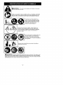
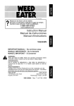
The blower can throw objects violently. You can be blinded or injured.
Always wear hearing protection and
safety glasses marked Z87. Always
wear heavy, long pants, long
sleeves, boots and gloves
1
O
Hazard zone for thrown objects. Keep children, bystanders, and animals away from work area a minimum of 30 feet (10 meters) when starting or operating
unit. Do not point blower nozzle in the direction of
people or pets.
not wear jewelry, loose clothing, or
clothing with loosing hanging straps,
ties, tassels, etc. They can be caught in
moving parts.
1Sec°rehairab°vesh°u'der'en0th
O°
, A
wYss°P
O
_ll
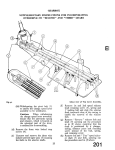
Wt&.R NING:
cleaning
or servicing
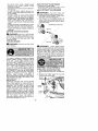
Stop the engine before opening the vacuum inlet door. The engine must
be stopped and the impeller blades no longer turning to avoid serious injury from the rotating
blades. Gently tilt the handle of the screwdriver toward the front of the unit to release the latch
while pulling up on the vacuum inlet cover with your other hand
-2-
I®
When using the vacuum attachment, the unit is designed to pick up dry
material such as leaves, grass, small twigs, and bits of paper Do not
vacuum stones, gravel, metal, broken glass, etc., to avoid severe damage to the impeller
WARNING: Fire hazard. Never mix, pour, or store gasoline or
use the unit near a flame or sparks (including smoking, open flames, or
work that can cause sparks).
WARNING: The muffler is very hot during and after use. Do
not touch the muffler, muffler guard, or surrounding
surfaces, or allow
combustible material such as dry grass or fuel to do so.
nWARNING:
Failure
and Precautions
to follow all
can result in
Safety Rules
serious injury.
KNOW
YOUR UNIT
• Read your instruction manual carefully until
you completely understand and can follow
all warnings and safety rules before operating the unit.
• Restrict unit to users who understand and
will follow all warnings and safety rules in
this manual
WARNING:
Inspect area before start-
•
•
•
•
ing unit. Remove all debris and hard objects
such as rocks, glass, wire, etc. that can ricochet, be thrown, or otherwise cause injury or
damage during operation.
Use your unit as a blower for:
• Sweeping debris or grass clippings from
driveways, sidewalks, patios, etc.
• Blowing grass clippings, straw, or leaves into
plies, around joints, or between bricks
Use your unit as a vacuum for:
• Picking up dry material such as leaves,
grass, small twigs, and bits of paper.
• For best results during vacuum use, operate
your unit at high speed.
• Move slowly back and forth over the material as you vacuum. Avoid forcing the unit
into a pile of debris as this can clog the unit.
• Keep the vacuum tube about an inch above
the ground for best resu_s.
PLAN AHEAD
• Always wear eye protection when operating, servicing, or performing maintenance
on unit. Wearing eye protection will help to
prevent rocks or debris from being blown or
ricocheting into eyes and face which can
-3-
•
result in blindness and/or serious injury.
Eye protection should be marked Z87
Always wear foot protection.
Do not go
barefoot or wear sandals.
Always wear respirator or face mask when
working with unit in dusty environments.
Secure hair so it is above shoulder length.
Keep loose hair, loose clothing, fingers, and
all other parts of the body away from openings
and moving parts. Hair, jewelry, loose clothing, or clothing with loosely hanging straps,
ties, tassels, etc., can be caught in moving
parts.
Do not operate unit when you are tired, i11,upset, or if you are under the influence of alcohol, drugs, or medication.
Keep children,
bystanders,
and animals
away from work area a minimum of 30 feet
(10 meters) when starting or operating unit.
Do not point the blower nozzle in the direction of people or pets
HANDLE
FUEL WITH CAUTION, IT IS
HIGHLY
FLAMMABLE
• Eliminate all sources of sparks or flame (including smoking, open flames, or work that
can cause sparks) in the areas where fuel is
mixed, poured, or stored
• Mix and pour fuel in an outdoor area; store
fuel in a cool, dry, well ventilated place; use
an approved, marked container for all fuel
purposes.
• Do not smoke while handling fuel or while
operating the unit.
• Make sure the unit is properly assembled
and in good operating condition.
• Do not fill fuel tank while engine is hot or
running.
• Avoid spilling fuet or oil. Wipe up fuel spills
before starting engine.
MAINTAIN
• Move at _east 10 feet (3 meters) away from
fuel and fueling site before starting engine.
• Always store gasoline in a container approved for flammable liquids.
OPERATE
YOUR
UNIT SAFELY
Ai_WARNING:
Stop the engine before
opening the vacuum inlet door. The engine
must be stopped and the impeller blades no
longer turning to avoid serious injury from the
rotating blades.
• Inspect unit before each use for worn,
loose, missing, or damaged parts. Do not
use unti_ unit is in proper working order.
• Keep outside surfaces free of oil and fuel.
• Never start or run engine inside a closed
room, building or other unventilated area.
Breathing exhaust fumes can kill.
• To avoid static electricity discharge, do not
wear rubber gloves or any other insulated
gloves while operating unit.
• Do not set unit on any surface except a
clean, hard area while engine is running.
Debris such as gravel, sand, dust, grass,
eta. could be picked up by the air intake and
thrown out through discharge
opening,
damaging unit, property, or causing serious
injury to bystanders or operator.
• Avoid dangerous environments.
Do not use
in unventilated
areas or where explosive
vapors or carbon monoxide build up could
be present.
• Do not overreach or use from unstable surfaces such as ladders, trees, steep slopes,
rooftops, etc. Keep firm footing and balance
at all times.
• Never place objects inside the blower
tubes; always direct the blowing debris
away from people, animals, glass, and solid
objects such as trees, automobiles, walls,
eta. The force of air can cause rocks, dirt, or
sticks to be thrown or to dcochet which can
hurt people or animals, break glass, or
cause other damage.
• Never run unit without the proper equipment attached. When using your unit as a
blower, always install blower tubes. When
using your unit as a vacuum, always install
vacuum tubes and vacuum bag assembly.
Make sure vacuum bag assembly is completaly zipped.
• Check air intake opening, blower tubes,
vacuum tubes, and elbow tube frequent{y,
always with engine stopped and spark plug
disconnected.
Keep vents and discharge
tubes free of debris which can accumulate
and restrict proper air flow.
• Never place any object in the air intake opening as this could restrict proper air flow and
cause damage to the unit.
• Never use for spreading chemicals, fertilizers, or other substances which may contain
toxic matadais.
• To avoid spreading fire, do not use near leaf
or brush fires, fireplaces,
barbecue pits,
ashtrays, eta
• Use only for jobs explained in this manual.
-4-
YOUR
UNIT
PROPERLY
WARNING:
Disconnect spark plug before performing maintenance except for carburetor adjustments.
• Have all maintenance
other than the recommended procedures described in the instruction manual performed by an authorized service dealer
• Use only recommended
Poulan PRO replacement
parts; use of any other parts
may void your warranty and cause damage
to your unit
• Empty fuel tank before storing the unit Use
up fuel left in carburetor by starting engine and
letting it run until it stops.
• Do not use any accessory or attachment
other than those recommended by manufacturer for use with your unit.
• Do not store the ueft or fuel in a closed area
where fuel vapors can reach sparks or an
open flame from hot water heaters, electric
motors or switches, furnaces, etc.
• Store in a dry area out of reach of children.
WARNING:
The engine exhaust from
this product contains chemicals known to the
State of California to cause cancer, birth defects or other reproductive
harm.
SPECIAL
NOTICE:
Exposure to vibrations through prolonged use of gasoline powered hand tools could cause blood vessel or
nerve damage in the fingers,
hands, and
joints of people prone to circulation disorders
or abnorma_ swelling Prolonged use in cold
weather has been _inked to blood vesset damage in otherwise healthy people. If symptams
occur
such as numbness,
pain, loss of
strength, change in skin color or texture, or
loss of feeling in the fingers, hands, or joints,
discontinue
the use of this tool and seek
medical
attention. An antivibration
system
does not guarantee the avoidance of these
problems. Users who operate power tools on
a continual and regular basis must monitor
closely their physical condition and the condition of this took
SPECIAL
NOTICE:
This unit is equipped
with a temperature
limiting muffler and spark
arresting screen which meets the requirements of California Codes 44-42 and 4443. All
U.S. forest land and the states of California,
Idaho, Maine, Minnesota, New Jersey, Oregon, and Washington
require by law that
many
internal
combustion
engines
be
equipped with a spark arresting screen. If you
operate in a locale where such regulations exist, you are legally responsible for maintaining
the operating condition of these parts. Failure
to do so is a violation of the law. Refer to the
MAINTENANCE
section for information
on
maintenance
of the muffler and spark arresting screen.
WARNING:
Stop engine and be sure
the impeller blades have stopped turning before opening the vacuum inlet door or attempting to insert or remove the vacuum or
b_ower tubes. The rotating blades can cause
serious injury. Always disconnect the spark
p_ug before performing maintenance
or accessing movable parts.
_:_WARNING;
If you receive your unit
assembled,
check each step to insure your
unit is properly assembled and all fasteners
are secure.
Follow all safety information in
the manual and on the unit
• A standard screwdriver
is required for assembly.
BLOWER
TUBE ASSEMBLY
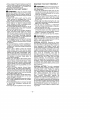
1. Align the fib on the upper blower tube with
the groove in the blower outlet; slide the
tube into place.
NOTE:
Knob must be loose enough to allow
blower tube to be inserted in blower outlet. Loosen knob by turning countercbckwise
6. To remove the tubes, turn the knob counterclockwise
to loosen the tubes; remove
the tubes.
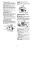
HIGH-SPEED
NOZZLE
ASSEMBLY
When greater air speed is desired, use the
high-speed
nozzle.
1. Align the slots on the nozzle with the tabs
on the lower blower tube
High-Speed
Nozzle
Lower Blower
Tab"
Tube
Slot
2. Slide the nozzle onto the lower blower tube.
3. Turn the nozzle clockwise until a click is
felt to secure the nozzle to the lower blower tube.
VACUUM
BAG ASSEMBLY
1. Open the zipper on the vacuum bag and
insert the elbow tube.
2. Push the small end of the elbow tube
through the small opening in the bag.
Elbow
Tube
Rib
Opening
2. Secure the tube by turning the knob clockwise.
3. Align the s_ots on the lower blower tube
with the tabs on the upper blower tube.
Small Opening
NOTE:
Make sure edge of the small opening
is flush against the flared area of the elbow tube,
and the rib on the elbow tube is on the bottom.
3. Close the zipper on the bag. Make sure the
zipper is closed completely.
4. Remove b_ower tubes from engine
Tube
Lower Blower
Tube
f
Tab
Slot
4. Slide the lower blower tube onto the upper
blower tube.
5. Turn the lower blower tube clockwise until
a click is felt to secure the lower blower
tube to the upper blower tube
NOTE:
When the upper and lower blower
tubes are assembled together properly, the
arrows on both tubes will be aligned
_
Groove
5. Insert the elbow tube into the blower outlet.
Make sure elbow tube rib Js aligned with
the blower outlet groove.
6. Turn knob clockwiseto
secure elbow tube.
VACUUM
TUBE ASSEMBLY
WARNING:
Stop engine and be sure
the impeller blades have stopped turning before opening the vacuum inlet door or attempting to insert or remove the vacuum or
-5-
b_ower tubes. The rotating blades can cause
serious injury
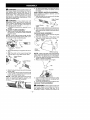
1. Insert the tip of a screwddver into the latch
area of the vacuum inlet.
6. Align slanted end of lower vacuum tube as
shown. Firmly push lower vacuum tube
into upper vacuum tube.
Slanted
Vacuum
Inlet Cover
2. Gently tilt the handle of the screwddver toward the front of the unit to release the
latch while pulling up on the vacuum inlet
cover with your other hand.
3. Hold the vacuum inlet cover open until upper vacuum tube is installed.
Vacuum
Inlet
Cover
Vacuum Inlet
4. Align thetabs on the inside of the vacuum inlet with the slots on the upper vacuum tube.
Tab
Slot
5. Push the upper vacuum tube into the vacuum inlet. Turn the tube counterclockwise
until a ctick is fa{t to secure the tube to the
blower unit.
-6-
end of
HOW TO CONVERT
UNIT FROM
VACUUM
USE TO BLOWER
USE
1. Remove the elbow tube and vacuum bag
by turning the knob counterc{ockwise
to
loosen the elbow tube.
2. Remove the vacuum tubes by turning the
tubes clockwise.
3. Close the vacuum inlet cover and make
sure it is tatched c{osed.
4. Reinstall the blower tubes (see SLOWER
TUBE ASSEMBLY)
SHOULDER
STRAP
ADJUSTMENT
1. Hold the unit as shown with the muffler side
facing away from your body and clothes.
2. Pass the shoulder strap over your head
and onto your right shoulder.
3. Extend your left arm toward the rear of the
vacuum bag.
4. Adjust shoulder strap until the vacuum
bag/shoulder
strap seam lies between
your thumb and index finger.
5. Make sure air flows freeiy from the eibow
tube into bag. tf bag is kinked, the unit will
not operate properly.
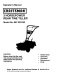
KNOW
YOUR
BLOWER
READ
THIS
INSTRUCTION
MANUAL
AND
SAFETY
RULES
BEFORE
OPERATING
YOUR
UNIT
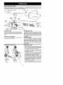
Compare the Jltustrations with your unit to famitJadze yourself with the location of the various controls
and adjustments. Save this manual for future reference.
Upper Vacuum Tube
Elbow Tube
Lower Vacuum
Throtbe
Trigger
STOP
Switch
_
Starter
Rope
Tube
Spark
Plug
Upper Blower Tube
Lower Blower Tube
High-Speed
Nozzle
Fuel Mix
Fill Cap
Primer
Button
STOP SWITCH
The STOP switch is used to stop the engine.
To stop the engine, push and hold the STOP
switch in the STOP position until the engine
stops.
THROTTLE
TRIGGER
The TH RO_LE
TRIGGER
the desired engine speed.
OPERATING
Blower
PRIMER
BUTTON
The PRIMER BU_ON
removes air fcom the
carburetor and fuel lines and tills them with fuel.
This alows you to start the engine with fewer
pulls on the starter rope. AcWate primer button
by pressing it and a,owing it to return to _tsoriginat position
CHOKE
LEVER
The CHOKE helps to supply fuel to the engine
to aid in cold starting. AcWate the choke by
moving the choke lever to the FULL CHOKE
position. After engine attempts to start, move the
choke lever to the HALF CHOKE position.
Once engine starts, move choke lever to the
RUN position.
is used to select
POSITION
OPERATING
TIPS
• Whi_e vacuuming
or blowing debris, hold
the unit with the muffler side facing away
from your body and clothes (see OPERATING POSITION
illustration above).
• To reduce
the risk of hearing
loss
associated
with sound level(s),
hearing
protection is required.
• To reduce the risk of injury associated with
contacting rotating parts, stop the engine before installing or removing attachments
Do
not operate without guard(s) in place.
• Operate power equipment only at reasonable
beurs-not early in the morning or late at night
when people might be disturbed. Comply with
times listed in local ordinances Usual recommendations
are 9:00 a.m. to 5:00 p.m.,
Monday though Saturday.
• To reduce noise levels, limit the number of
pieces of equipment used at any one time.
Vacuum
-7-
• To reduce noise _eveis, operate power
blowers
at the lowest possible throttle
speed to do the job
• Use rakes and brooms to loosen debds before blowing.
• In dusty conditions,
slightly dampen surfaces or use a mister attachment when water is available.
• Conserve water by using power blowers
instead of hoses for many lawn and garden
applications, including areas such as gutters,
screens, patios, grills, porches, and gardens.
• Watch out for children, pets, open windows,
or freshly washed cars. Blow debris away
safely.
• Use the full blower nozzle extension so the
air stream can work close to the ground.
• After using blowers and other equipment,
CLEAN UP! Dispose of debris in trash receptacles.
BEFORE
STARTING
ENGINE
_WARNING:
HOW TO STOP YOUR ENGINE
• Release the throttle trigger.
• Push and hold the STOP switch in the
STOP ,osition until the engine stops.
HOW TO START
YOUR
ENGINE
Ai_WARNING:
You MUST
make
sure
the tubes are secure before using the unit.
• Fuel engine Move at least 10 feet (3 meters) away from the fueling site.
• Hold the unit in the starting position as
shown. Make sure the blower end is directed away from people, animals, glass,
and solid objects.
STARTING
POSITION
/
Blower
Be sure to read the fuel
information in the safety rules before you begin. If you do not understand the safety rules,
do not attempt
to fuel your
unit. Call
1-800-554-6723.
FUELING
ENGINE
Ai_WARNING:
/
Remove fuet cap s_owly
when refueling.
_WARNING:
This engine is certified to operate on unleaded
gasoline. Before operation, gasoline must be
mixed with a good quality synthetic 2-cycle
air-cooled engine oil designed to be mixed at a
ratio of 40:1. Poulan PRO brand synthetic oil is
recommended. Mix gasefine and oil at a refJo of
40:1. A 40:1 ratio is obtained by mixing 32
ounces (95 ml) of oil with 1 gallon (4 liters) of
unleaded gasoline. DO NOT USE automotive
oil or marine oil These oils will cause engine
damage. When mixing fuel, follow instructions
printed on container
Once oil is added to
gasoline,
shake container
momentarily
to
assure that the fuel is thoroughly mixed. Always
read and feflow the safety rules relating to fuel
before fueling your unit.
IMPORTANT
Experience
indicates that a_cohol blended
fuels (called gasohol or using ethanol or
methanef) can attract moisture which leads to
separation
and formation
of acids during
storage.
Acidic gas can damage the fue{
system of an engine while in storage. To avoid
engine problems,
empty the fuel system
before storage for 30 days or longer. Drain the
gas tank, startthe engine and let it run until the
fuel lines and carburetor are empty. Use fresh
fuel next season.
Never use engine or
carburetor cleaner products in the fuel tank or
permanent damage may occur.
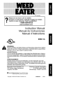
-8-
When starting engine,
hold the unit as itlustrated. Do not set unit on any
surface except a clean, hard area when starting
engine or while engine is running. Debris such
as gravel, sand, dust, grass, etc. could be
picked up by the air intake and thrown out
through the discharge opening, damaging the
unit or property, or causing serious injury to bystanders or the operator
STARTING
A COLD ENGINE
(or warm
engine
after running
out of fuel)
1. Slowly press the primer bulb 6 times.
2. Move choke lever to the FULL CHOKE pesirich.
3. Squeeze the throttle trigger fully and hold
through all remefeft_J steps
Starter
Handle
Choke
Primer
Bulb
4
5
6
7
Pull starter rope handle sharply until engine
sounds as if it is trying to start, but do not pull
rope more than 6 times.
As soon as engine sounds as if it is trying to
start, move choke lever to HALF CHOKE
position.
Pull starter rope sharply until engine runs,
but no more than 6 pulls. NOTE:
If the engine does n't start after 6 pulis (at the HALF
CHOKE position), move the choke lever to
the FULL CHOKE position and press the
primer bulb 6 times. Squeeze and hold the
throttle trigger and pull the starter rope 2
more times. Move the choke lever to the
HALF CHOKE position and pull the starter
rope until the engine runs, but no more
than 6 pulls. If the engine still doesn't start,
it is probably flooded. Proceed to STARTiNG A FLOODED ENGtNE.
Once the engine starts, allow it to run 10 seconds, then move the choke lever to the
RUN posifJon. Allow the unit to run for 30
more seconds at RUN before releasing the
throttle trigger. NOTE:
if engine dies with
the choke lever in the RUN position, move
IlllWAPIHII_IIJ:
Avoid touching
muffler
unless engine and muffler are cold.
A hot
muffler can cause serious burns.
WARNING:
Stop engine and be sure
the impeller blades have stopped turning before opening the vacuum inlet door or attempting to insert or remove the vacuum or
blower tubes. The rotating blades can cause
serious injury. Always disconnect the spark
plug before performing maintenance
or accessing movable parts.
the choke lever to the HALF CH O KE position and pull the rope until engine runs, but
no more than 6 pulls.
STARTING
A WARM
ENGINE
1. Move the choke _ever to the HALF CHOKE
position
2. Squeeze the throttle thgger fully and hold
through all remefnfl_J steps
3. Pull starter rope sharply unfll engine runs,
but no more than 6 pulls.
4. Allow engine to run 15 seconds, then move
the choke lever to RUN
NOTE:
If engine has not started, putl starter
rope 5 more pulls If engine still does not run, it
is probably flooded.
STARTING
A FLOODED
ENGINE
Flooded engines can be started by placing the
choke raver in the RUN pcefflon; then, poll the
rope to clear the engine of excess fuel. This
could require polling the starter handle many
times depending on how badb! the unit is
flooded If the unit stil_ doesn't start, refer to
TROUBLESHOOTING
TABLE
or
call
1-800-554--6723.
CHECK
FOR LOOSE
FASTENERS
AND PARTS
• Muffler
• Spark P{ug Boot
•A{r Filter
• Housing Screws
CHECK
FOR DAMAGED
OR WORN
PARTS
Contact an authorized service dealer for rep{acement of damaged or worn parts.
• PuelTank - Donot useunitiffueltankshows
signs of damage or leaks.
• Vacuum Bag - Do not use vacuum bag if it
is torn or damaged
INSPECT
AND CLEAN
UNIT AND
DECALS
• After each use, inspect complete unit for
loose or damaged parts. Clean the unit and
decets using a damp cbth with a mild detergent.
• Wipe off unit with a clean dry cloth.
CLEAN
AIR FILTER
A dirty air filter decreases
engine performance and increases
fuel consumption
and
harmful emissions. Always clean or reptace
air filter after every 5 hours of operation or
yearly, whichever comes first
Button _-'T
AirFilter
GENERAL
#/_
RECOMMENDATIONS
The warranty on this u nit does not cover items
that have been subjected to operator abuse
or negligence.
To receive full value from the
warranty, the operator must maintain unit as
instructed in this manual
Various adjustments will need to be made periodically to
properly maintain your unit
-9-
Air FiItei_!
_
Cleaning
the air filter:
1. Clean the cover and the area around it to
keep debds from falling into the carburetor
chamber when the cover is removed
NOTE:
Move choke lever to RUN position
before opening air fi_ter cover.
2. Open air filter cover by pushing button
(see illustration)
Remove air filter.
NOTE:
Do not clean filter in gasoline or other
flammable solvent. Doing so can create a fire
hazard or produce harmful evaporative emissions.
3. Wash the filter in soap and water.
4. Allow filter to dry.
5. Apply a few drops of oil to the filter;
squeeze fi_ter to distribute oil
6. Replace parts.
REPLACE
SPARK
PLUG
Replace spark p_ug each year to ensure the
engine starts easier and runs better. Set
spark plug gap at 0.025 inch (0.6 mm) Ignition timing is fixed, nonadjustable.
1. Twist, then pull off spark plug boot.
2. Remove spark plug from cylinder and discard.
3. Replace with Champion
RCJ-6Y
spark
plug and tighten securely with a 3/4 inch
(19 mm) socket wrench.
4. Reinstall the spark plug boot.
REPLACE
FUEL FILTER
To replace fuel filter, drain unit by run ning it dry
of fuel, then remove fuel cap/retainer assembly from tank Pull filter from tank end remove
it from the fuel line. Install new fuel filter on fuel
line; reinstall parts
CHECK MUFFLER MOUNTING
SCREWS
Once each year, ensure muffler mounting
screws are tightened securely to prevent
damage.
f-
Muffler
' Mounting
Screw
INSPECT
MUFFLER
AND
ARRESTING
SCREEN
SPARK
WARNING: The muffler on this product contains chemicals known to the State of
California to cause cancer.
As the unit is used, carbon deposits build up
on the muffler and spark arresting screen,
and must be removed to avoid creating a fire
hazard or affecting engine performance
Muffler Cover
Spark
Arresting
1
/
/ Hood
/
Fuel Filter
Screws
Replace the spark arresting screen every 50
hours of operation or if any damage or breaks
in the screen are noted
NOTE:
Do not attempt to c_ean the spark arresting screen.
1. Remove 3 screws from muffler cover.
Remove muffler cover
2. Loosen and remove 4 screws from the
muffler hood.
3. Remove the muffler hood and spark arresting screen.
4. Install new spark arresting screen.
5. Reinstallmuffier
hood and 4 screws. Tighten screws securely.
6. Reinstall muffler cover and 3 screws.
Tighten securely.
NOTE:
If any part of the muffler is cracked,
broken or damaged, we recommend that the
muffler be replaced.
-10-
CARBURETOR
ADJUSTMENT
The carburetor has been carefully set at the
factory. Adjustments may be necessary if you
notice any of the following conditions:
• Engine will not idle when the throttle is released.
Idle Speed Screw
Idle Speed
Adjustment
Allow engine to idle. Adjust speed until engine
runs without stalling (idle speed too slow).
• Turn idle speed screw clockwise
to increase engine speed if engine stalls or dies.
• Turn idle speed screw counterclockwise
to
decrease engine speed.
Filter
Air
Cover
_
_--
If you require further assistance or are unsure
about performing this procedure, contact an
authorized
service
dealer
or
call
1-800-554-6723.
nWARNING:
Perform the following
steps after each use:
• Allow engine to cool, and secure the unit
before storing or transporting.
• Store unit and fuel in a well ventilated area
where fuel vapors cannot reach sparks or
open flames from water heaters, electric
motors or switches, furnaces, etc.
• Store unit with all guards in place. Position
unit so that any sharp object cannot accidentally cause injury.
• Store unit and fuel well out of the reach of
children.
SEASONAL
STORAGE
Prepare unit for storage at end of season or if
it will not be used for 30 days or more
If your unit is to be stored for a period of time:
• Clean the entire unit before lengthy storage.
• Store in a clean dry area.
• Lightly oil external metal surfaces
FUEL SYSTEM
Under FUELING
ENGINE in the OPERATION section of this manual, see messagelabe{ed IMPORTANT regarding the use of gasohol in your engine
Fuel stabilizer is an acceptable alternative in
minimizing the formatbn of fuel gum deposits
dudng storage. Add stabilizer to gasoline in fuel
tank or fuel storage containen Follow the mix
instructions found on stabilizer container Run
engine at least 5 minutes after adding stabilizes
-11
ENGINE
• Remove spark p_ug and pour 1 teaspoon of
40:1,2-cycle
engine oil (air cooled) through
the spark plug opening. Slowly pull the
starter rope 8 to 10 times to distribute oil.
• Replace spark plug with new one of recommended type and heat range.
• Clean air filter
• Check entire unit for loose screws, nuts,
and bolts. Replace any damaged, broken,
or worn parts.
• At the beginning of the next season, use
only fresh fuel having the proper gasoline to
oil ratio.
OTHER
• Do not store gasoline from one season to
another.
• Replace your gasoline can if it starts to rust.
-
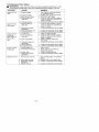
TROUBLESHOOTING
_
TABLE
WARNING:
Always stop unit and disconnect spark plug before performingany of the
recommended remedies below other than remedies that require operation of the unit.
TROUBLE
CAUSE
Engine will not
start.
REMEDY
1. Engine flooded.
2. Fuel tank empty.
3. Spark g_ug not firing.
4. Fuel not reaching
carburetor.
5. Compression
Engine will not
idle properly.
low
;i
l.
carburetor.
Engine will not
accelerate,
lacks power, or
1+ Air filter dirty.
2. Fue{ not reaching
carburetor.
dies under a
load.
4 Spark
3.
Carburetor
plug fouled.
requires
i2. Contact an authorized service dealer.
i 3. Contact an authorized service dealer
' 4. Contact an authorized service dealer.
i 5. Contact an authorized service dealer.
;; 6. Contact an authorized service dealer.
1. Choke partially on.
J 2. Fuel mixture incorrect.
i
3. Air filter dirty.
4-. Carburetor requires
ad ustment.
1. Fuel mixture
Check
or filter;
split fuel
line;
heck for
for kinked
dirty fue{
replace
repair or replace.
1. Clean or replace air filter.
2. Check for dirty fue{ filter; replace.
Check for kinked or split fuel line;
repair or replace.
3. Clean
sparkservice
plug dealer.
4.
Contact oranreplace
authorized
and re-gap
adjustment.
5. Carbon build up.
6. Compression
low.
Engine runs hot.
Check for kinked or split fuel line;
Check for dirty fue{ filter; replace.
repair or replace.
5. Contact an authorized service dealer.
ii4.
1. Fuel not reaching
. Carburetor
adjustment. requires
;; 3. Crankshaft seals worn
4. Compression
low
Engine smokes
excessively+
11. in
SeeOperation
"Starting section.
a Flooded Engine"
2. Fill tank with correct fuel mixture.
3. Install new spark plug.
incorrect.
2. Spark plug incorrect.
3. Carburetor requires
adjustment.
4+ Carbon build up
1 Adjust choke.
2 Empty fuel tank and refill with
correct fuel mixture.
;; 3 Clean or replace air filter.
4 Contact an authedzed service dealer
;;1. See "Fueling Engine" in Operation
section.
2. Replace with correct spark plug.
3. Contact an authorized service dealer.
4. Contact an authorized service dealer.
-12-
Poulan PRO, a division of Husqvarna Outdoor
Products Inc., warrants to the odginal consumer
purchaser that each new Foulan PRO brand
gasoline tao_ or attachment is free from defects
in material and workmanship and agrees to repair or replace under this warranty any defective
gasoline product or attachment as fo_bws from
the odginal date of purchase.
2 YEARS - Parts and Labor, when used for
household purposes.
90 DAYS - Parts and Labor, when used for
commercial, professional, or income producing
purposes.
30 DAYS - Parts and Labor, if used for rental
purposes.
This warranty is not transferable and does not
cover damage or liability caused by improper
handling, improper maintenance or alteration,
or the use of accessories and/or attachments
not specifically
recommended
by Poulan
PRO for this tool. This warranty does not cover tune-up, spark plugs, filters, starter ropes,
or blower and vacuum tubes that will wear
and require replacement with reasonable use
during the warranty
period. This warranty
does not cover pre-delivery
setup or normal
adjustments
explained
in the instruction
manual. This warranty does not cover transportation costs.
In the event you have a claim under this warranty, you must return the product to an authorized
service dealer.
Should you have any unanswered questions
concerning this warranty, p_ease contact:
Poulan PRO, a dMsion of
Husqvama Outdoor Products Inc
1030 Stevens Creek Road
Augusta, GA 30907
1-800-554-6723
In Canada, contact:
Poulan PRO
5855 Terry Fox Way
Mississauga, Ontario L5V3E4
YOUR WARRANTY RIGHTS AND OBLIGATIONS: The U.S. Environmental
Protection
Agency, California Air Resources Board, Environment
Canada and Poulan
PRO are
pleased to explain the emissions control system warranty on your year 2007 and later
small off-road engine. In California, all small
off-road engines must be designed, built, and
equipped to meet the State's stringent antismog standards. Poulan PRO must warrant
the emission control system on your small
off-road engine for the periods of time listed
below provided there has been no abuse, neglect, or improper maintenance
of your small
off-road
engine. Your emission control system includes parts such as the carburetor, the
ignition system and the fuel tank (California
only). Where a warrantable condition exists,
Poulan PRO will repair your small off-road
engine engine at no cost to you. Expenses
covered under warranty include diagnosis,
parts and labor.
MANUFACTURER'S
WARRANTY
COVER=
AGE: If any emissions related part on your engine (as listed under Emissions Control Warranty Parts Ust) is defective or a defect in the materials or workmanship of the engine causes the
failure of such an emission related part, the part
will be repaired or replaced by Poulan PRO.
OWNER'S
WARRANTY
RESPONSIBILI=
TIES: As the small off-road engine engine owner, you are responsible for the performance of
the required maintenance {isted in your instruction manual Poulan PRO recommends that you
retain all receipts covering maintenance on your
small off-road engine, but Poulan PRO cannot
deny warranty solely for the lack of receipts or
for your failure to ensure the performance of all
scheduled maintenance. As the small off-toed
engine engine owner, you should be aware that
Poulan PRO may deny you warranty coverage
if your small off- road engine engine or a part of it
has failed due to abuse, neglect, improper maintenance, unapproved 1_3difications, or the use
Giving the model number, serial number and
date of purchase of your product and the name
and address of the authorized dealer from
whom it was purchased.
THIS WARRANTY
GIVES YOU SPECIFIC
LEGAL RIGHTS, AND YOU MAY HAVE OTHER RIGHTS WHICH VARY FROM STATE TO
STATE.
NO CLAIMS FOR CONSEQUENTIAL
OR
OTHER
DAMAGES
WILL BE ALLOWED,
AND THERE ARE NO OTHER EXPRESS
WARRANTIES
EXCEPT
THOSE
EXPRESSLY STIPULATED HEREIN.
SOME STATES DO NOT ALLOW LIMITATIONS ON HOW LONG AN IMPLIED WARRANTY LASTS OR THE EXCLUSION OR
LIMITATIONS OF INCIDENTAL OR CONSEQUENTIAL DAMAGES, SO THE ABOVE LIMITATIONSOR EXCLUSION MAY NOT APPLY
TO YOU.
This is a lim_fedwarranty within the meaning of
that term as defined inthe Magnuson-Moss Act
of 1975.
The policy of Poutan PRO is to continuously
improve
its products.
Therefore,
Poulan
PRO reserves the right to change, modify, or
discontinue models, designs, specifications,
and accessories
of all products at any time
without notice or obligation to any purchaser.
13-
of parts not made or approved by the orkjinaJ
equipment manufacturer. You are responsible
for presenting your small off-road engine to an
Poulan PRO authorized repair center as soon
as a problem exists. Warranty repairs should be
completed in a reasonable amount of time, not
to exceed 30 days. If you have any questions
regarding your warranty rights and responsibilities, you should contact your nearest authorized
service
center or call Poulan
PRO
at
1-800-554-6723.
WARRANTY
COMMENCEMENT DATE: The warranty period begins on the date the smell off-road engine {s
purchased.
LENGTH OF COVERAGE:
This
warranty shall be for a period of two years from
the initial date of purchase.
WHAT IS COVERED: REPAIR OR REPLACEMENT
OF
PARTS. Repair or replacement of any warranted part will be performed at no charge to the
owner at an approved Poulan PRO servicing
center If you have any questions regarding your
warranty rights and respensibil4es, you should
contact your nearest authorized service center
or carl Poulan PRO at 1-800-554-6723.
WARRANTY PERIOD: Any warranted part which is
not scheduled for replacement
as required
maintenance, or which is scheduled only for
regular inspecfion to the effect of 'repair or replace as necessary" shat_ be warranted for 2
years. Any warranted part which is scheduled
for replacement as required maintenance shall
be warranted for the period of time up to the first
scheduled
replacement
point for that part.
DIAGNOSIS:
The owner
sha_l not be
charged for diagnostic labor which leads to
the determination that a warranted part is defective if the diagnostic work is performed at
an approved Poulan PRO servicing center
CONSEQUENTIAL
DAMAGES: Poulan PRO
may be liable for damages to other engine components caused by the failure of a warranted
part still under warranty. WHAT IS NOT COVERED: All failures caused by abuse, neglect, or
improper metntenance are not covered. ADD=
ON OR MODIFIED PARTS: The use of edd-on
or modified parts can be grounds for disallowing
a warranty claim. Poulan PRO is not {iable to
cover failures of warranted parts caused by the
use of add-on or modified parts.
HOW TO FILE A CLAIM: If you have any questions regarding your warranty rights and responsibilities, you should contact your nearest authorized service center or carl Poulan PRO at
1-800-554-6723.
WHERE TO GET WARRANTY SERVtCE: Warranty services or repairs shall be provided at aJlPoulan PRO service centers. Carl 1-800-554-6723.
MAINTENANCE, REPLACEMENT
AND REPAIR OF
EMISSION RELATED PARTS: Any Poulan
PRO approved replacement part used in the
performance of any warranty maintenance or
repair on emission related parts will be provided
without charge to the owner if the part is under
warranty. EMISSION CONTROL WARRANTY
PARTS LIST: Carburetor,
Ignition System:
Spark P_ug (covered up to maintenance schedule), Ignition Module, Muffler including Cata_st,
Fuel Tank (California only). MAINTENANCE
STATEMENT: The owner is responsible for the
performance of all required maintenance as defined in the instruction manual
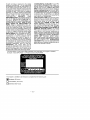
The information on the product labet indicates which standard your engine is certified.
Example: (Year) EPA Phase 1 or Phase 2 and/or CALIFORNIA.
This engine is certified to be emissions compliant for the following use:
[]
Moderate (50 hours)
[]
Intermediate (125 hours)
[]
Extended (300 hours)
-14-