1
54/108Mbps Super A+G
Wireless Access Point
WDAP-2000PE
User’s Manual
Copyright
Copyright© 2005 by PLANET Technology Corp. All rights reserved. No part of this publication may be reproduced, transmitted, transcribed, stored in a retrieval system, or translated
into any language or computer language, in any form or by any means, electronic, mechanical,
magnetic, optical, chemical, manual or otherwise, without the prior written permission of
PLANET.
PLANET makes no representations or warranties, either expressed or implied, with respect to
the contents hereof and specifically disclaims any warranties, merchantability or fitness for
any particular purpose. Any software described in this manual is sold or licensed "as is".
Should the programs prove defective following their purchase, the buyer (and not this company, its distributor, or its dealer) assumes the entire cost of all necessary servicing, repair,
and any incidental or consequential damages resulting from any defect in the software. Further, this company reserves the right to revise this publication and to make changes from time
to time in the contents hereof without obligation to notify any person of such revision or
changes..
All brand and product names mentioned in this manual are trademarks and/or registered
trademarks of their respective holders.
Federal Communication Commission Interference Statement
This equipment has been tested and found to comply with the limits for a Class B digital device, pursuant to Part 15 of FCC Rules. These limits are designed to provide reasonable
protection against harmful interference in a residential installation. This equipment generates,
uses, and can radiate radio frequency energy and, if not installed and used in accordance
with the instructions, may cause harmful interference to radio communications. However,
there is no guarantee that interference will not occur in a particular installation. If this equipment does cause harmful interference to radio or television reception, which can be
determined by turning the equipment off and on, the user is encouraged to try to correct the
interference by one or more of the following measures:
1. Reorient or relocate the receiving antenna.
2. Increase the separation between the equipment and receiver.
3. Connect the equipment into an outlet on a circuit different from that to which the receiver
is connected.
4. Consult the dealer or an experienced radio technician for help.
FCC Caution:
To assure continued compliance.(example-use only shielded interface cables when connecting to computer or peripheral devices). Any changes or modifications not expressly approved
by the party responsible for compliance could void the user’s authority to operate the equipment.
This device complies with Part 15 of the FCC Rules. Operation is subject to the Following two
conditions: (1) This device may not cause harmful interference, and (2 ) this Device must
accept any interference received, including interference that may cause undesired operation.
Federal Communication Commission (FCC) Radiation Exposure
Statement
This equipment complies with FCC radiation exposure set forth for an uncontrolled environment. In order to avoid the possibility of exceeding the FCC radio frequency exposure limits,
human proximity to the antenna shall not be less than 20 cm(8 inches) during normal operation.
ii
Safety
This equipment is designed with the utmost care for the safety of those who install and use it.
However, special attention must be paid to the dangers of electric shock and static electricity
when working with electrical equipment. All guidelines of this and of the computer manufacture must therefore be allowed at all times to ensure the safe use of the equipment.
CE Mark Warning
This is a Class A product. In a domestic environment, this product may cause radio interference, in which case the user may be required to take adequate measures.
Revision
User’s Manual for PLANET 54/108Mbps Super A+G Wireless Access Point
Model: WDAP-2000PE
Rev: 1.0 (August, 2005)
Part No. EM-WDAP2000PE
iii
TABLE OF CONTENTS
CHAPTER 1 INTRODUCTION ......................................................................... 3
1.1 Package Contents .......................................................................................... 3
1.2 Features........................................................................................................... 3
1.3 Physical Details .............................................................................................. 4
1.4 Specification ................................................................................................... 5
1.6 Wireless Performance.................................................................................... 6
CHAPTER 2 INSTALLATION........................................................................... 7
2.1 General Installation ........................................................................................ 7
2.2 Using PoE (Power over Ethernet) ................................................................. 7
CHAPTER 3 SETUP & MANAGEMENT .......................................................... 9
3.1 Overview.......................................................................................................... 9
3.2 Setup using a Web Browser.......................................................................... 9
3.3 Setup Wizard................................................................................................. 10
3.3.1 Time Settings......................................................................................... 10
3.3.2 Device IP Settings ................................................................................. 10
3.3.3 Wireless Settings................................................................................... 11
3.3.4 Save Config ........................................................................................... 13
3.4 Device Status ................................................................................................ 14
3.4.1 System Log............................................................................................ 14
3.4.2 Wireless Client Table ............................................................................ 14
3.4.3 Bridge Table .......................................................................................... 15
3.4.4 Radio Table ........................................................................................... 16
3.4.5 Site Survey Table .................................................................................. 16
3.5 Advanced Settings ....................................................................................... 17
3.5.1 Password Settings................................................................................. 17
3.5.2 System Management ............................................................................ 17
3.5.3 SNMP Settings ...................................................................................... 19
3.5.4 MAC Filtering Settings........................................................................... 20
3.5.5 SSID Settings ........................................................................................ 21
3.5.6 Wireless Settings................................................................................... 23
3.5.7 Operational Mode.................................................................................. 24
3.5.8 RADIUS Settings................................................................................... 25
3.5.9 DoS Settings.......................................................................................... 26
3.6 System Tools ................................................................................................ 28
3.6.1 Firmware Upgrade................................................................................. 28
3.6.2 Configuration Save and Restore ........................................................... 29
3.6.3 Factory Default ...................................................................................... 30
3.6.4 Reboot System ...................................................................................... 30
CHAPTER 4 PC AND SERVER CONFIGURATION...................................... 31
4.1 Overview........................................................................................................ 31
4.2 Using WEP..................................................................................................... 31
4.3 Using WPA-PSK............................................................................................ 31
4.4 Using WPA .................................................................................................... 32
4.5 WPA / 802.1x Server Setup (Windows 2000 Server) ................................. 32
4.5.1 Windows 2000 Domain Controller Setup .............................................. 33
4.5.2 Services Installation .............................................................................. 33
4.5.3 DHCP server configuration ................................................................... 34
4.5.4 Certificate Authority Setup..................................................................... 36
4.5.5 Internet Authentication Service (Radius) Setup .................................... 39
i
4.5.6 Grant Remote Access for Users ........................................................... 40
4.6 802.1x Client Setup on Windows XP .......................................................... 41
4.6.1 Client Certificate Setup.......................................................................... 41
4.6.2 802.1x Authentication Setup ................................................................. 44
4.7 Using 802.1x Mode ....................................................................................... 47
APPENDIX A TROUBLESHOOTING............................................................ 48
APPENDIX B COMMAND LINE INTERFACE .............................................. 49
Using the CLI - Telnet......................................................................................... 49
Command Reference.......................................................................................... 49
ii
Chapter 1
Introduction
1
PLANET WDAP-2000PE is an IEEE 802.11a+g dual band Wireless Access Point with PoE. With the latest innovative Super A/G technology integrated,
the maximum data rate of WDAP-2000PE is 108Mbps, which doubles the speed of
standard 802.11a/g. WDAP-2000PE is also backward compatible and interoperable
with IEEE 802.11b compliant wireless devices.
Emphasizing on the enterprise demand, WDAP-2000PE enhances many security
and management features, including multiple SSIDs, VLAN, QoS, DiffServ support,
WPA/WPA2, DoS Prevention and so on. The LAN port of WDAP-2000PE has PoE
function conforming to IEEE 802.3af, providing both data transfers and power
supply through one Ethernet cable. Therefore, it can be installed anywhere without
the constraint on power socket. Provided with two reversed-polarity SMA male
connector, WDAP-2000PE is easy to connect external antenna and booster to
extend the wireless distance.
1.1 Package Contents
Make sure that you have the following items:
WDAP-2000PE
Dipole Antenna x 2
Quick Installation Guide
User’s manual CD-ROM
Power Adapter
Note:
If any of the above items are missing or damaged, contact your supplier for
support.
1.2 Features
Wireless LAN IEEE802.11a+g and IEEE802.11b compliant
Support PoE port (IEEE802.3af compliant)
Strong network security with 802.1x authentication, and 64/128/152-bit WEP encryption
WPA and WPA2* with PSK/TKIP/AES support
Super A/G mode efficiently raises the data transfer rate up to 108Mbps
Two operation modes selectable for both 5GHz and 2.4GHz radios: AP / WDS mode
Adjustable transmit power and data rate
Watchdog timer, NTP client and basic UPnP support
Provide Web and CLI (Command Line Interface) Configuration
SNMP management support (V1/V2, Traps, MIB2, IF MIB, Ether-like MIB, 802.11-MIB)
Support Multiple SSIDs, 802.1Q VLAN, 802.1p QoS, DiffServ, DoS Prevention, MAC
filtering.
* WPA2 feature will be available in the end of 2005 Q3.
3
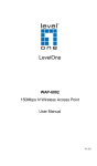
1.3 Physical Details
Top View
LED
POWER PWR
Status Description
Steady Green – Power on
OFF – Power off
Steady Green - Link is active
Link/Act Flashing Green - Transmit or receive data
OFF - No connection
LAN
Steady Green - Link is active on 100M speed
100M
Flashing Green - Transmit or receive data
OFF - Link is active on 10M speed
Steady Green - Link is active on 802.11a
mode
5 GHz
Flashing Green - Transmit or receive data
OFF - No connection
WLAN
Steady Green - Link is active on 802.11b/g
mode
2.4GHz
Flashing Green - Transmit or receive data
OFF - No connection
4
Installation
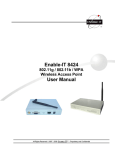
Rear View
Connector
Description
ANT
Two dipole antennas are supplied. Best result is usually
obtained with the antenna in a vertical position.
Power
Connect the supplied power adapter here.
In order to clear ALL settings and restore to factory
Reset Button default, holding the Reset Button down continuously for 5
seconds.
LAN (PoE)
Use a standard LAN cable (RJ-45 connectors) to connect
this port to a 10BaseT or 100BaseT hub on your LAN.
1.4 Specification
Model
WDAP-2000PE
Standard
IEEE 802.11b, 802.11g, 802.11a
Signal Type
DSSS (Direct Sequence Spread Spectrum)
Modulation
OFDM with BPSK, QPSK, 16QAM, 64QAM, DBPSK, DQPSK,
CCK
Port
10/100Mbps RJ-45 port * 1, 802.3af compliant
Antenna Connector
Reverse SMA male x 2
Wireless Transmit
Power
IEEE802.11a mode: 17dBm@54Mbps
20dBm@6Mbps
IEEE802.11g mode: 17dBm@54Mbps
20dBm@11Mbps
20dBm@1Mbps
IEEE802.11b mode: 14dBm
Wireless Receive
Sensitivity
IEEE802.11a mode: -85dBm@6Mbps
-65dBm@54Mbps
IEEE802.11g mode: -91dBm@1Mbps
-84dBm@11Mbps
-65dBm@54Mbps
Operating Mode
AP, WDS mode
Security
WEP, WPA with PSK/TKIP/AES support
802.1x authentication /EAP-TLS/EAP-TTLS/EAP-MD5/EAPPEAP
MAC filtering authorized
Block SSID broadcast
5
Management
Web based configuration
CLI configuration
Message Log
Firmware upgrade
UPnP support
Configuration file Backup/Restore
Data Rate
Super A/G mode Up to 108Mbps
802.11g
Up to 54Mbps (6/9/12/18/24/36/48/54)
802.11b
Up to 11Mbps (1/2/5.5/11)
Dimensions (L x W x
H)
190 x 145 x 28mm
Weight
320g
Operating temperature: 0 – 40 degree C
Environmental SpecifiStorage temperature: -20 – 65 degree C
cation
Relative humanity: 10% – 90% (non-condensing)
Power Requirement
5V DC, 2A
Electromagnetic
Compatibility
FCC, CE
1.6 Wireless Performance
The following information will help you utilizing the wireless performance, and operating coverage of WDAP-2000PE.
1. Site selection
To avoid interferences, please locate WDAP-2000PE and wireless clients away from
transformers, microwave ovens, heavy-duty motors, refrigerators, fluorescent lights, and
other industrial equipments. Keep the number of walls, or ceilings between AP and clients
as few as possible; otherwise the signal strength may be seriously reduced. Place WDAP2000PE in open space or add additional WDAP-2000PE as needed to improve the coverage.
2. Environmental factors
The wireless network is easily affected by many environmental factors. Every environment
is unique with different obstacles, construction materials, weather, etc. It is hard to determine the exact operating range of WDAP-2000PE in a specific location without testing.
3. Antenna adjustment
The bundled antenna of WDAP-2000PE is adjustable. Firstly install the antenna pointing
straight up, then smoothly adjust it if the radio signal strength is poor. But the signal reception is definitely weak in some certain areas, such as location right down the antenna.
Moreover, the original antenna of WDAP-2000PE can be replaced with other external antennas to extend the coverage. Please check the specification of the antenna you want to
use, and make sure it can be used on WDAP-2000PE.
4. WLAN type
If WDAP-2000PE is installed in an 802.11b and 802.11g mixed WLAN, its performance will
reduced significantly. Because every 802.11g OFDM packet needs to be preceded by an
RTS-CTS or CTS packet exchange that can be recognized by legacy 802.11b devices.
This additional overhead lowers the speed.
6
Installation
Chapter 2
Installation
2
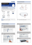
2.1 General Installation
Before you proceed with the installation, it is necessary that you have enough information about
the WDAP-2000PE.
1. Locate an optimum location for the WDAP-2000PE. The best place for your WDAP2000PE is usually at the center of your wireless network, with line of sight to all of your
mobile stations.
2. Assemble the antennas to WDAP-2000PE. Try to place them to a position that can
best cover your wireless network. The antenna’s position will enhance the receiving
sensitivity.
3. Connect RJ-45 cable to WDAP-2000PE. Connect this WDAP-2000PE to your LAN
switch/hub or a single PC.
4. Plug in power adapter and connect to power source. After power on, WDAP-2000PE
will start to operate.
Note: ONLY use the power adapter supplied with the WDAP-2000PE. Otherwise, the
product may be damaged.
2.2 Using PoE (Power over Ethernet)
The LAN port of WDAP-2000PE supports PoE. Before you proceed with the PoE installation,
please make sure the PoE adapter or switch is 802.3af compliant.
1. Do not connect the supplied power adapter to the WDAP-2000PE.
2. Connect one end of a standard (category 5) LAN cable to the Ethernet port on the
WDAP-2000PE.
3. Connect the other end of the LAN cable to the powered Ethernet port on a suitable PoE
Adapter or switch. (IEEE 802.3af compliant)
4. Check the LEDs on the WDAP-2000PE to see it is drawing power via the Ethernet
connection.
NOTE: ONLY use the IEEE802.3af complied in-line power equipments to the
Access Point. Connect with any other non-standard in-line power device may
cause the AP malfunction.
7
Chapter 3
Setup & Management
3
3.1 Overview
This chapter describes the setup procedure to make the WDAP-2000PE a valid device on your
LAN, and to function as an Access Point for your Wireless Stations.
The WDAP-2000PE can be configured using either the Web Browser or the CLI (Command Line
Interface). Please refer to appendix B for the commands of CLI.
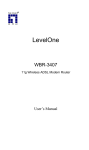
3.2 Setup using a Web Browser
Web configuration provides a user-friendly graphical interface to manage your WDAP-2000PE.
An AP with an assigned IP address (default http://192.168.1.1) will allow you to monitor and
configure (via web browser e.g., MS Internet Explorer or Netscape).
Before proceeding, please install the WDAP-2000PE in your LAN, as described in chapter 2.
1.
2.
3.
4.
Use a PC which is already connected to your LAN, and start the Web browser.
In the Address box, enter the IP address of the WDAP-2000PE you want to configure.
Please also make sure your PC’s IP address is in the same IP subnet with WDAP-2000PE.
You should see a main configuration screen in the web page as the picture below.
If you attempt to access any configuration item, a dialog box will pop up and ask for login
password. The default value is “password”. The password can and should be changed to
avoid unauthorized access. Always enter the current password, as set on the “Advanced
Settings” screen.
9
If you can't connect:
It is likely that your PC’s IP address is incompatible with the WDAP-2000PE’s IP
address. The default IP address of the Wireless Access Point is 192.168.1.1, with a
Network Mask of 255.255.255.0.
If your PC’s IP address is not compatible with this, you must change your PC’s IP
address to an unused value in the range 192.168.1.2 ~ 192.168.1.254, with a
Network Mask of 255.255.255.0.
3.3 Setup Wizard
The setup wizard helps you to configure the basic settings of WDAP-2000PE in four steps.
3.3.1 Time Settings
The time of WDAP-2000PE is automatically synchronized to the local time of the management
PC at the first time a connection is made. To modify the device’s time, select desired setting for
each field. Click “NEXT” to proceed.
Enable NTP
You can enable the NTP function and configure the server name/IPaddress of the NTP server you want to use. Once NTP is enabled, the
system will set its own date/time to the value returned fromthe NTP
server.
Local time
zone/date and
time
Please choose the time zone according to your location and set the data
and time.
3.3.2 Device IP Settings
You can manually configure the IP settings to WDAP-2000PE, or use DHCP client protocol to
obtain IP address automatically. Click “NEXT” to proceed.
10
Assign static IP
If selected, the following data must be entered.
to this device
•
IP Address - The IP Address of this device. Enter an unused IP
address from the address range on your LAN.
•
Subnet Mask - The Network Mask associated with the IP Address
above. Enter the value used by other devices on your LAN.
•
Gateway - The IP Address of your Gateway or Router. Enter the
value used by other devices on your LAN.
•
DNS - Enter the DNS (Domain Name Server) used by PCs on your
LAN.
Use the DHCP
protocol to …
Select this option if you have a DHCP Server on your LAN, and you
want the WDAP-2000PE to obtain an IP address automatically.
3.3.3 Wireless Settings
You can set the SSID, Operating Standard and Channel of 5GHZ and 2.4GHz radios, Common
Security Policy in this page. Click “NEXT” to proceed.
11
Network ID (SSID)
The SSID (up to 32 printable ASCII characters) is the unique
name identified in a WLAN. The ID prevents the unintentional
merging of two co-located WLANs. Please make sure that the
SSID of all stations in the same WLAN network are the same. The
default SSID is “default”.
If this option is unselected, every wireless station located within
Disable SSID Broadcasting the coverage of this access point can discover this access point
easily. Disabling "Broadcast SSID" can provide better security and
privacy.
Regulatory Domain
WLAN standard for Radio
1/2
Please make sure that your regulatory domain matches your
region.
Mode: Set the mode for each radio. Radio1 only operates on the
5 GHz frequency and radio2 only operates on the 2.4 GHz frequency. So radio1 can be configured with 11a or Super A, and
radio2 can be configured with 11g/b, 11b only, 11g only, and
Super G.
Channel: Select the appropriate channel for each radio from the
list provided to correspond with your network settings. It is suggested to select Auto and let the system pick up the best channel
for you.
Select Common Secu-
None: No security is used. Anyone using the correct SSID can
connect to your network.
12
rity Policy
connect to your network.
WEP: WDAP-2000PE allows you to use WEP data encryption to
secure your data from being eavesdropping by unauthorized
users. There are WEP64, WEP128 and WEP152 provided for
data encryption.
You can either use ASCII format or Hex format to enter a key.
With Hex format, 2 digits represent 1 byte. Once you enable the
WEP function, please make sure that exactly the same WEP keys
are set on the Wireless AP as well as on wireless client stations.
Note: Some Wireless Client Card used for Hexadecimal digits
only. Please note that when configuring WEP encryption keys, a
WEP128 ASCII key looks like "An ASCII key!" (13 characters),
while a WEP64 hex key looks like "441224A8B2"(5 characters).
802.1x: Use 802.1x to do authentication and provide encryption (if
rekeying is enabled). An external RADIUS server should be setup,
and you also need to complete the configurations on “RADIUS
Settings” page under “Advanced Settings” tab.
WPA-PSK: Use WPA-PSK to provide security, you need to enter
an ASCII key for this mode. Different encryption types can be
used: TKIP, CCMP, or both. A group key is used for multicast/broadcast data, and the rekey interval is time period that the
system will change the group key periodically. The shorter the
interval is, the better the security is.
WPA: This version of WPA requires a Radius Server on your LAN
to provide the client authentication according to the 802.1x standard. You would also need to complete the configurations on
“RADIUS Settings” page under “Advanced Settings” tab. Data
transmissions are encrypted using the WPA standard. Different
encryption types can be used: TKIP, CCMP, or both. A group key
is used for multicast/broadcast data, and the rekey interval is time
period that the system will change the group key periodically. The
shorter the interval is, the better the security is.
3.3.4 Save Config
After stepping through the Wizard’s pages, you can press the “FINISH” button on this page for
your modification to take effect. This also makes your new settings saved into the permanent
memory on your system.
13
3.4 Device Status
You can monitor the system general information from the Device Information field.
3.4.1 System Log
The system log allows you to track events that have occurred in the system. Such event messages can sometimes be helpful in determining the cause of a problem that you may have
encountered.
3.4.2 Wireless Client Table
The wireless client table lists the current wireless clients and its MAC address, state, and traffic
statistics.
14
3.4.3 Bridge Table
The bridge table shows all MAC entries learned from the wired LAN interface, wireless clients,
and WDS peers (if running in the WDS mode).
15
3.4.4 Radio Table
Radio table lists current Mode, channel, client associated with them and transmit packet, received packet, data error.
3.4.5 Site Survey Table
This page shows other APs currently in the environment that the system can detect.
16
3.5 Advanced Settings
The advanced settings tab contains more configurations for experienced users. However,
changing your login password from the default factory setting is highly recommended for security purposes.
3.5.1 Password Settings
The default administrative password is “password”. To change the password, type the current
password followed by the new password twice. The entered characters will appear as asterisks.
Click “APPLY” to save the new setting.
3.5.2 System Management
Clicking the System Management button to configure system related parameters.
17
Local Management
System Administration
UPnP
This option allows you to enable/disable management from WLAN
connection.
The Access Point allows you to designate special port numbers
other than the standard 80 for http for remote management. It
also allows you to specify the duration of idle time (inactivity)
before a web browser session times out. The default time-out
value is 10 minutes.
The Universal Plug and Play (UPnP) feature allows a Windows
XP/ME PC to discover this WDAP-2000PE and automatically
show an icon on the screen. Then a user can double-click the icon
to access this device directly (without having to find out its IP
address).
18
Bridge
Syslog
Email Log
You can enable/disable the 802.1d STP (Spanning Tree Protocol)
function on the bridge of WLAN and Ethernet (i.e. the LAN interface). Enable this function can detect loops in your LAN
environment and then protect the LAN from being saturated with
infinite loop traffic.
When the WDAP-2000PE encounters an error or warning condition (e.g., a log-in attempt with an invalid password), it will create
a log in the system log table. Enabling Syslog option, the WDAP2000PE will send logged events over network to the specified
server for remote storage and future reviewing.
If you check the "Enable Email Log" button, the WDAP-2000PE
will send log information to the configured email address through
the configured mail server.
3.5.3 SNMP Settings
Enable SNMP
SNMP enables network administrators to manage network performance, find and solve network problems. When SNMP feature
19
are enabled, the device can send out TRAP messages automatically to the TRAP manager if configured.
Assign System Information
System Name: A name that you assign to your WDAP-2000PE. It
is an alphanumeric string of up to 30 characters.
System Location: Description of where your WDAP-2000PE is
physically located. It is an alphanumeric string of up to 60 characters.
System Contact: Contact information for the system administrator responsible for managing your WDAP-2000PE. It is an
alphanumeric string of up to 60 characters.
Assign the SNMP Community String
Community String For Read: If you intend the access point to
be managed from a remote SNMP management station, you need
to configure a read-only “community string” for readonly operation.
The community string is an alphanumeric string of up to 15
characters.
Community String For Write: For read-write operation, you
need to configure a write “community string”.
Assign a specific name
and IP address …
A trap manager is a remote SNMP management station where
special SNMP trap messages are generated (by the Access
Point) and sent to in the network. You can define trap managers
in the WDAP-2000PE.
You can add a trap manager by entering a name, an IP address,
followed by pressing the ADD button.
You can delete a trap manager by selecting the corresponding
entry and press the DELETE SELECTED button.
You can enable a trap manager by checking the Enable box in
the corresponding entry or disable the trap manager by unchecking the Enable box.
3.5.4 MAC Filtering Settings
The WDAP-2000PE allows you to define a list of MAC addresses that are allowed or denied to
access the wireless network.
20
When selected, no MAC address filtering will be performed.
Disable MAC address
control list
Enable GRANT address
When selected, data traffic from only the specified devices in the
table will be allowed in the network.
control list
Enable DENY address
When selected, data traffic from the devices specified in the table
will be denied/discarded by the network.
control list
To add a MAC address into the table, enter a mnemonic name and the MAC address, and click
ADD.
The table lists all configured MAC Filter entries. To delete entries, check the corresponding
select boxes and then press DELETE SELECTED.
3.5.5 SSID Settings
The WDAP-2000PE allows you to configure multiple SSID's and correspondiing QoS settings if
QoS is enabled.
21
Once this function is enabled, you can specify an individual VLAN
Enable VLAN for all SSIDs ID and priority tag for each SSID. In this way, you can separate
traffic from stations using different SSIDs and so protect the wired
network from being accessed by unauthorized stations using
certain SSIDs. If this function is enabled, packets from a SSID will
be forwarded to the Ethernet with the corresponding configured
VLAN tag.
Enable QoS
Enable DiffServ Marking
Enable QoS function allows you to assign a priority for each SSID.
Then the traffic to/from a WLAN station will have a priority set for
the SSID the station is using. If the VLAN function is enabled, the
priority is given by the 802.1p priority configured. Otherwise, the
priority is set by choosing one of the four service levels.
When this function is enabled, you can configure a DSCP value
for each SSID. Then a packet from a station using this SSID to
get associated will be forwarded with the DSCP value labeled.
These buttons allow you to CLEAR the content of the SSID
NEW, DELETE SELECTED, configuration items currently displayed, DELETE the selected
SSID entry, and SET the selected SSID to be the primary SSID.
SET AS PRIMARY
The string of SSID.
SSID name
VLAN ID
The VLAN ID for this SSID. This item is available only when the
VLAN function is enabled.
802.1p priority
The 802.1p priority for this SSID. This item is available only when
the VLAN function is enabled.
DSCP value
The DSCP value (a 6-bit pattern) for this SSID when the DiffServ
Marking function is enabled.
22
Configure the security policy for the SSID.
Select security policy
3.5.6 Wireless Settings
Beacon interval
The WDAP-2000PE broadcasts beacon frames regularly to
announce its existence. Default is 100, i.e., ten beacons per
second. Decreasing the beacon interval makes passive
scanning more reliable and faster. Increasing the beacon
interval may improve throughput by decreasing contention
for the medium.
RTS threshold
RTS/CTS frames are used to gain control of the medium for
transmission. If there are heavy traffic from many stations,
decrease RTS threshold will reduce collision. The RTS
threshold should have a value between 256-2347 bytes, with a
default of 2347. It is recommended that this value does not
deviate from the default too much.
23
Fragmentation
DTIM interval
When the size of a unicast frame exceeds the fragmentation
threshold, it will be fragmented before the transmission. It should
have a value of 256-2346 bytes, with a default of 2346. If you
experience a high packet error rate, you should slightly decrease
the Fragmentation Threshold.
The WDAP-2000PE buffers packets for stations that operate in
the power saving mode. The Delivery Traffic Indication Message
(DTIM) informs such power conserving stations that there are
packets waiting to be received by them. The DTIM interval specifies how often the beacon frame should contain DTIMs. It should
have a value between 1 to 255, with a default value of 1.
User limitation
Set the number of users allowed to get associated with your
WDAP-2000PE.
Enable privacy seperator
Enable Privacy Separator will make any two WLAN stations on
different networks unable to see each other.
Radio 1/Radio 2 Transmit
This is the power degree in percentage (max.: 100%) that radio1/radio2 uses to transmit data.
Power
This is the maximum or fixed data rate to transmit data supported.
Rate control
Age out timer
If a station does not send anything in age out time, a empty date
frame will be sent to the station, If this frame is not ACKed, the
station will be disassociated and then deauthenticated.
3.5.7 Operational Mode
Select a Radio to config-
Currently, each radio of the WDAP-2000PE can be configured to
operate in AP or WDS mode. When configured as a WDS, you
need to further configure the name and MAC address of its peer
24
WDS devices.
ure
Access Point
This means the device is working on AP-only Mode, and is for
wireless client users only.
Wireless Distribution
This mode can help you to group different wired networks together by multiple WDAP-2000PE. The single system can support
up to 8 WDAP-2000PE in WDS mode.
System (Bridge mode)
Additional configurations
for WDS mode
If the device is working on 'Wireless Distribution System (Bridge
Mode)', you must add the MAC addresses of the grouped WDAP2000PE to the table.
Peer name: Alias to help you recognize another WDS station.
MAC address: The MAC address of other WDS AP you want to
add into this group.
3.5.8 RADIUS Settings
The Radius server can be used for 802.1x EAP authentication. IEEE 802.1x is an IEEE standard that is based on a framework that involves stations to be authenticated (called Supplicant),
an authentication server (a Radius Server) that provides authentication services, and an authenticator that provides necessary translation and mediating functions between the authentication
server and the stations to be authenticated. The WDAP-2000PE acts as an authenticator, and it
relays authentication messages between the RADIUS server and client devices being authenticated.
IEEE 802.1x EAP authentication is enabled by selecting the Security Policy as 802.1x or WPA,
and this selection is in the Wireless Settings under Setup Wizard.
25
Check this if you want to enable RADIUS authentication using the
Enable Primary/Secondary primary/secondary Radius Server. If both are selected, the primary server will be tried first.
Server
The IP address of the RADIUS server.
Server IP
Port number
Shared secret
Retry times
The port number that your RADIUS server uses for authentication. The default setting is 1812.
This is used by your RADIUS server in the Shared Secret field in
Radius protocol messages. The shared secret configured in the
WDAP-2000PE and the RADIUS server must be identical. The
shared secret can contain up to 64 alphanumeric characters.
The number of times the WDAP-2000PE should attempt to
contact the primary server before giving up.
3.5.9 DoS Settings
A Denial of Service attack is one of the popular hacking methods. The attacker tries to make
some resource too busy to answer legitimate requests, or to deny legitimate users access to
your machine. WDAP-2000PE can be configured to prevent such attack.
Authentication fails
Broadcast storm filtering
You can set a maximum failure count. When the number of times
that a WLAN station fails to authenticate itself reaches this count,
the station (identified by its MAC address) will be put into a
rejectee list. So the station will not be even authenticated any
more.
Once a station is put into the rejectee list, you can remove it from
the table at the bottom of this page.
When the broadcast traffic reaches the configured degree (e.g.
High, Low), any more broadcast packets will be dropped. Higher
degree allows less broadcast traffic pass through.
26
Ping flooding filtering
When the ping (to the AP) traffic reaches the configured degree
(e.g. High, Low), any more such ping packets will be dropped.
Higher degree allows less ping traffic to the AP.
27
3.6 System Tools
3.6.1 Firmware Upgrade
You can upgrade the firmware of your WDAP-2000PE. Normally, this is done when a new
version of firmware is released.
Upgrade procedures:
Step 1: Select System Tools
Firmware Upgrade from the menu.
Step 2: To update the WDAP-2000PE firmware, first download the firmware from the distributor’s web site to your local disk, and then from the above screen enter the path and filename of
the firmware file (or click Browse to locate the firmware file). Next, Click the Upgrade button to
start.
The new firmware will begin being loaded to your WDAP-2000PE. After a message appears
telling you that the operation is completed, you need to reset the system to have the new firmware take effect.
28
3.6.2 Configuration Save and Restore
You can save system configuration settings to a file, and later download it back to the WDAP2000PE by following the steps below.
Step 1: Select Configuration Save and Restore from the System Tools menu.
Step 2: Enter the path of the configuration file to save-to/restore-from (or click the Browse
button to locate the configuration file). Then click the SAVE TO FILE button to save the current
configuration into the specified file, or click the RESTORE FROM FILE button to restore the
system configuration from the specified file.
29
3.6.3 Factory Default
You can reset the configuration of your WDAP-2000PE to the factory default settings.
Step 1: Select Factory Default from the System Tools menu.
Step 2: Click YES to go ahead and restore the configuration to the factory default.
3.6.4 Reboot System
You can reset your WDAP-2000PE from the Browser.
Step 1: Select Reboot System from the System Tools menu.
Step 2: Click YES to reboot the WDAP-2000PE.
30
Chapter 4
PC and Server Configuration
4
4.1 Overview
All Wireless Stations need to have settings which match the Wireless Access Point.
These settings depend on the mode in which the WDAP-2000PE is being used.
•
If using WEP or WPA-PSK, it is only necessary to ensure that each Wireless
station's settings match those of the WDAP-2000PE, as described below.
•
For WPA and 802.1x modes, configuration is much more complex. The Radius
Server must be configured correctly, and setup of each Wireless station is also
more complex.
4.2 Using WEP
For each of the following items, each Wireless Station must have the same settings as
the WDAP-2000PE.
Mode
On each PC, the mode must be set to Infrastructure.
SSID (ESSID)
This must match the value used on the WDAP-2000PE.
The default value is default
Note: The SSID is case sensitive.
Wireless
Security
•
Each Wireless station must be set to use WEP data encryption.
•
The Key size (64 bit, 128 bit, 152 bit) must be set to match the
WDAP-2000PE.
•
The keys values on the PC must match the key values on the
WDAP-2000PE.
Note:
On some systems, the key sizes may be shown as 40bit, 104bit,
and 128bit instead of 64 bit, 128 bit and 152bit. This difference
arises because the key input by the user is 24 bits less than the
key size used for encryption.
4.3 Using WPA-PSK
For each of the following items, each Wireless Station must have the same settings as
the WDAP-2000PE.
Mode
On each PC, the mode must be set to Infrastructure.
SSID (ESSID)
This must match the value used on the WDAP-2000PE.
The default value is default
Note: The SSID is case sensitive.
Wireless
S
On each client, Wireless security must be set to WPA-PSK.
31
Security
•
The Pre-shared Key entered on the WDAP-2000PE must
also be entered on each Wireless client.
•
The Encryption method (e.g. TKIP, AES) must be set to
match the WDAP-2000PE.
4.4 Using WPA
This is the most secure and most complex system.
WPA mode provides greater security and centralized management, but it is more
complex to configure.
Wireless Station Configuration
For each of the following items, each Wireless Station must have the same settings as
the WDAP-2000PE.
Mode
On each PC, the mode must be set to Infrastructure.
SSID (ESSID)
This must match the value used on the WDAP-2000PE.
The default value is default
Note: The SSID is case sensitive.
802.1x Authentication
Each client must obtain a Certificate which is used for authentication for the Radius Server.
802.1x Encryption
Typically, EAP-TLS is used. This is a dynamic key system, so
keys do NOT have to be entered on each Wireless station.
However, you can also use a static WEP key (EAP-MD5); the
WDAP-2000PE supports both methods simultaneously.
Radius Server Configuration
If using WPA mode, the Radius Server on your network must be configured as follow:
•
It must provide and accept Certificates for user authentication.
•
There must be a Client Login for the WDAP-2000PE itself.
•
The WDAP-2000PE will use its Default Name as its Client Login name.
•
The Shared Key, set on the Security Screen of the WDAP-2000PE, must match
the Shared Secret value on the Radius Server.
•
Encryption settings must be correct.
4.5 WPA / 802.1x Server Setup (Windows 2000 Server)
This section describes using Microsoft Internet Authentication Server as the Radius
Server, since it is the most common Radius Server available that supports the EAPTLS authentication method.
The following services on the Windows 2000 Domain Controller (PDC) are also required:
•
dhcpd
•
dns
32
•
rras
•
webserver (IIS)
•
Radius Server (Internet Authentication Service)
•
Certificate Authority
4.5.1 Windows 2000 Domain Controller Setup
1. Run dcpromo.exe from the command prompt.
2. Follow all of the default prompts, ensure that DNS is installed and enabled during
installation.
4.5.2 Services Installation
1. Select the Control Panel - Add/Remove Programs.
2. Click Add/Remove Windows Components from the left side.
3. Ensure that the following components are activated (selected):
•
Certificate Services. After enabling this, you will see a warning that the computer cannot be renamed and joined after installing certificate services. Select
Yes to select certificate services and continue
•
World Wide Web Server. Select World Wide Web Server on the Internet Information Services (IIS) component.
•
From the Networking Services category, select Dynamic Host Configuration
Protocol (DHCP), and Internet Authentication Service (DNS should already be
selected and installed).
4. Click Next.
5. Select the Enterprise root CA, and click Next.
33
6. Enter the information for the Certificate Authority, and click Next.
7. Click Next if you don't want to change the CA's configuration data.
8. Installation will warn you that Internet Information Services are running, and must
be stopped before continuing. Click Ok, then Finish.
4.5.3 DHCP server configuration
1. Click on the Start - Programs - Administrative Tools - DHCP
2. Right-click on the server entry as shown, and select New Scope.
34
3. Click Next when the New Scope Wizard Begins.
4. Enter the name and description for the scope, click Next.
5. Define the IP address range. Change the subnet mask if necessary. Click Next.
6. Add exclusions in the address fields if required. If no exclusions are required,
leave it blank. Click Next.
7. Change the Lease Duration time if preferred. Click Next.
8. Select Yes, I want to configure these options now, and click Next.
9. Enter the router address for the current subnet. The router address may be left
blank if there is no router. Click Next.
10. For the Parent domain, enter the domain you specified for the domain controller
setup, and enter the server's address for the IP address. Click Next.
35
11. If you don't want a WINS server, just click Next.
12. Select Yes, I want to activate this scope now. Click Next, then Finish.
13. Right-click on the server, and select Authorize. It may take a few minutes to
complete.
4.5.4 Certificate Authority Setup
1. Select Start - Programs - Administrative Tools - Certification Authority.
2. Right-click Policy Settings, and select New - Certificate to Issue.
3. Select Authenticated Session and Smartcard Logon (select more than one by
holding down the Ctrl key). Click OK.
36
4. Select Start - Programs - Administrative Tools - Active Directory Users and Computers.
5. Right-click on your active directory domain, and select Properties.
6. Select the Group Policy tab, choose Default Domain Policy then click Edit.
37
7. Select Computer Configuration - Windows Settings - Security Settings - Public
Key Policies, right-click Automatic Certificate Request Settings - New - Automatic
Certificate Request.
8. When the Certificate Request Wizard appears, click Next.
9. Select Computer, then click Next.
38
10. Ensure that your certificate authority is checked, then click Next.
11. Review the policy change information and click Finish.
12. Click Start - Run, type cmd and press enter.
Enter secedit /refreshpolicy machine_policy
This command may take a few minutes to take effect.
4.5.5 Internet Authentication Service (Radius) Setup
1. Select Start - Programs - Administrative Tools - Internet Authentication Service
2. Right-click on Clients, and select New Client.
3. Enter a name for the access point, click Next.
4. Enter the IP address of the WDAP-2000PE, and set the shared secret, as entered
on the Security Profile screen of the WDAP-2000PE.
5. Click Finish.
6. Right-click on Remote Access Policies, select New Remote Access Policy.
7. Assuming you are using EAP-TLS, name the policy eap-tls, and click Next.
8. Click Add...
If you don't want to set any restrictions and a condition is required, select DayAnd-Time-Restrictions, and click Add...
39
9. Click Permitted, then OK. Select Next.
10. Select Grant remote access permission. Click Next.
11. Click Edit Profile... and select the Authentication tab. Enable Extensible Authentication Protocol, and select Smart Card or other Certificate. Deselect other
authentication methods listed. Click OK.
12. Select No if you don't want to view the help for EAP. Click Finish.
4.5.6 Grant Remote Access for Users
1. Select Start - Programs - Administrative Tools- Active Directory Users and Computers.
2. Double click on the user who you want to enable.
40
3. Select the Dial-in tab, and enable Allow access. Click OK.
4.6 802.1x Client Setup on Windows XP
Windows XP ships with a complete 802.1x client implementation. If using Windows
2000, you can install SP4 (Service Pack 4) to gain the same functionality.
If you don't have either of these systems, you must use the 802.1x client software
provided with your wireless adapter. Refer to the documentation of your wireless
adapter for setup instructions.
The following instructions assume that:
•
You are using Windows XP
•
You are connecting to a Windows 2000 server for authentication.
•
You already have a login (User name and password) on the Windows 2000 server.
4.6.1 Client Certificate Setup
1. Connect to a network which doesn't require port authentication.
2. Start your Web Browser. In the Address box, enter the IP address of the Windows
2000 Server, followed by /certsrv
For example: http://192.168.1.2/certsrv
3. You will be prompted for a user name and password. Enter the User name and
Password assigned to you by your network administrator, and click OK.
41
4. On the first screen (below), select Request a certificate, click Next.
5. Select User certificate request and select User Certificate, the click Next.
42
6. Click Submit.
7. A message will be displayed, then the certificate will be returned to you.
Click Install this certificate.
43
8. . You will receive a confirmation message. Click Yes.
9. Certificate setup is now complete.
4.6.2 802.1x Authentication Setup
1. Open the properties for the wireless connection, by selecting Start - Control Panel
- Network Connections.
2. Right Click on the Wireless Network Connection, and select Properties.
3. Select the Authentication Tab, and ensure that Enable network access control
using IEEE 802.1X is selected, and Smart Card or other Certificate is selected
from the EAP type.
44
Encryption Settings
The Encryption settings must match the APs (WDAP-2000PE) on the Wireless network you want to join.
•
Windows XP will detect any available Wireless networks, and allow you to configure each network independently.
•
Your network administrator can advise you of the correct settings for each network. 802.1x networks typically use EAP-TLS. This is a dynamic key system, so
there is no need to enter key values.
Enabling Encryption
To enable encryption for a wireless network, follow this procedure:
1. Click on the Wireless Networks tab.
45
2. Select the wireless network from the Available Networks list, and click Configure.
3. Select and enter the correct values, as advised by your Network Administrator.
For example, to use EAP-TLS, you would enable Data encryption, and click the
checkbox for the setting: The key is provided for me automatically, as shown below.
Setup for Windows XP and 802.1x client is now complete.
46
4.7 Using 802.1x Mode
The procedures are similar to using 802.1x.
The only difference is that on your client, you must NOT enable the setting: The key is
provided for me automatically.
Instead, you must enter the WEP key manually, ensuring it matches the WEP key
used on the Access Point.
Note:
On some systems, the "64 bit" WEP key is shown as "40 bit" and the "128 bit" WEP
key is shown as "104 bit". This difference arises because the key input by the user is
24 bits less than the key size used for encryption.
47
Appendix A
Troubleshooting
Problem 1:
Can't connect to the WDAP-2000PE to configure it.
Solution 1:
Check the following:
A
•
The WDAP-2000PE is properly installed, LAN connections are
OK, and it is powered ON. Check the LEDs for port status.
•
Ensure that your PC and the WDAP-2000PE are on the same
network segment. (If you don't have a router, this must be the
case.)
•
If your PC is set to "Obtain an IP Address automatically" (DHCP
client), restart it.
If your PC uses a Fixed (Static) IP address, ensure that it is using an
IP Address which is compatible with the WDAP-2000PE. (If no DHCP
Server is found, the WDAP-2000PE will default to an IP Address and
Mask of 192.168.1.1 and 255.255.255.0.) On Windows PCs, you can
use Control Panel-Network to check the Properties for the TCP/IP
protocol.
Problem 2:
My PC equipped with wireless adapter can't connect to the LAN
via the WDAP-2000PE.
Solution 2
Check the following:
•
The SSID and WEP settings on the PC match the settings on the
WDAP-2000PE.
•
On the PC, the wireless mode is set to "Infrastructure"
•
If using the Access Control feature, the PC's name and address
is in the Trusted Stations list.
•
If using 802.1x or WPA mode, ensure the PC’s 802.1x software
is configured correctly.
Problem 3:
How to improve the stability of my wireless connection?
Solution 3
•
Try different antenna orientations for WDAP-2000PE. Keep the
antenna at least 6 inches away from walls or obstacles.
•
If there are 2.4GHz cordless phones, home security systems,
ceiling fans existing in the same environment, the wireless performance will be dramatically dropped. Try to change the
operating channel of WDAP-2000PE to avoid interference.
•
Keep the wireless devices away (at least 3-6 feet) from electrical
devices that generate RF noise, such as microwave ovens, electric motors, etc.
Problem 4:
What if I forget the login password of WDAP-2000PE?
Solution 4
If you forgot the password, the only way to recover is to clear the
device configuration and return the unit to its original state as shipped
from the factory. You can do this by pressing the hardware “RESET”
button on the back of the device and hold for five seconds. Please
note that this will also clear your current configuration and restore the
configuration from the factory default.
48
Appendix B
Command Line Interface
B
If desired, the Command Line Interface (CLI) can be used for configuration. This creates the
possibility of creating scripts to perform common configuration changes.
Using the CLI - Telnet
1.
2.
Start your Telnet client, and establish a connection to the WDAP-2000PE.
e.g.
Telnet 192.168.1.1
You will be prompted for the password. Enter the same login password as used for the
HTTP (Web) interface.
The default values are password for the Password.
3.
Once connected, you can use any of the commands listed in the following Command
Reference.
4.
At any time, the users can type a “?” (preceded by a space) to request context-sensitive
help on what the user can enter next.
If a keyword is expected when the user types “?”, all valid keywords will be displayed. The
command typed in so far will then be displayed again along with the cursor sitting at the end,
waiting for the user to continue.
If the user types in part of the keyword but does not type in the entire word, the user can
then enter a tab or space for the system to automatically complete the keyword if the characters typed in so far can uniquely identify the keyword. If the characters typed in so far do
not uniquely identify a keyword, a list of possible keywords will be displayed.
5.
6.
Command Reference
The following commands are available.
(1) System Commands
Clear config
Description: Reset the system configuration to the factory default.
Disable upnp
Description: Disable the UPnP function.
Disable wlan management
Description: Disable the management function from a WLAN connected user.
enable upnp
Description: Enable the UPnP function.
enable wlan management
Description: Enable the management function from a WLAN connected user.
help
Description: Show help descriptions on CLI.
logout
Description: Logout the current CLI management session.
ping <IP address>
Description: Show help descriptions on CLI.
reset system
Description: Reboot the system. Any configuration not saved (e.g. by “save config”) will be lost.
save config
Description: Save the current configuration onto the flash, so the configuration will be kept after
the system is rebooted.
set http port <port number, 1-65535>
49
Description: Set the HTTP server port (for device management) to the one specified.
set http timeout <timeout value in minutes, 1-60>
Description: Set the timeout value for the HTTP management session.
set prompt <string up to 15 characters>
Description: Set the command line prompt.
set system contact <string up to 60 characters>
Description: Configure a string describing the system contact information. This is the value of
the SNMP system contact MIB.
set system ip
Description: Set the IP address for the device LAN interface.
set system location <string up to 60 characters>
Description: Configure a string describing the system location information. This is the value of
the SNMP system location MIB.
set system name <string up to 30 characters>
Description: Configuring a string for the system name. This is also the value of the SNMP
system name MIB.
set telnet port <port number, 1-65535>
Description: Set the TELNET server port (for device management) to the one specified.
set telnet timeout <timeout value in minutes, 1-60>
Description: Set the timeout value for a TELNET management session.
show arp table
Description: Display the ARP table of the system.
show http
Description: Display the current configurations of the HTTP management function.
show system
Description: Display the current basic system configurations.
show system ip
Description: Display the current device IP settings of the system.
show telnet
Description: Display the current configurations of the TELNET management function.
show upnp
Description: Display the current configurations of the UPnP function.
show wlan management
Description: Display the current state of WLAN management.
(2) Filtering Commands
add mac filter <string up to 30 characters> <MAC address, XX-XX-XX-XX-XX-XX>
Description: Add a MAC filter with the specified name (a mnemonic name) and MAC address.
delete mac filter <string up to 30 characters>
Description: Delete the MAC filter with the specified name.
set mac filter mode <MAC filter mode, disabled/grant/deny>
Description: Set the MAC filter mode.
show mac filter [<string up to 30 characters>]
Description: Display the MAC filter entry with the specified name. If no name is specified, this
command display all currently configured MAC filter entries.
show mac filter mode
Description: Display the currently configured MAC filter mode.
(3) SNMP Commands
disable snmp
Description: Disable the SNMP function.
enable snmp
Description: Enable the SNMP function.
set community string {read | write} <string up to 15 characters>
Description: Configure the SNMP READ/WRITE community string.
show community string read
Description: Display the SNMP READ community string.
show snmp
Description: Display the current SNMP settings.
50
show snmp statistics
Description: Display the current SNMP statistics.
show trap manager [<string up to 30 characters>]
Description: Display the settings of the specified SNMP trap manager. If no trap manager is
specified, this command displays the settings of all trap managers.
(4) Diagnostics Commands
disable log <facility>
Description: Disable the log function on the specified facility.
disable syslogd
Description: Disable the remote log function.
disable trace <facility>
Description: Disable the trace function on the specified facility.
enable log <facility> [<log level, 1-7>]
Description: Enable the log function with the specified log level on the specified facility. If no log
level is specified, the previously configured log level is used.
enable syslogd
Description: Enable the remote log function.
enable trace <facility> [<log level, 1-7>]
Description: Enable the trace function with the specified log level on the specified facility. If no
log level is specified, the previously configured log level is used.
set log level <log level, 1-7>
Description: Set the log level.
set syslogd <IP address>
Description: Configure the IP address of the remote syslog daemon. This is used for the remote
syslog function.
show log level
Description: Display the current log level.
show log table [<facility>]
Description: Display the current logged events of the specified facility. If no facility is specified,
this command displays all logged events.
show syslogd
Description: Display the current configuration of the remote log function.
(5) Security Commands
add radius server {primary | secondary}
Description: Configure the primary/secondary RADIUS server settings. This is a multi-line
command, and you have to enter the IP address and port number of the server, shared secret,
and enable/ disable.
change password
Description: Change the password for management, including HTTP and TELNET.
disable radius mac authentication
Description: Disable the use of external RADIUS servers for MAC address access control.
disable radius server {primary | secondary}
Description: Disable the use of the primary/secondary RADIUS server.
enable radius mac authentication
Description: Enable the use of external RADIUS servers for MAC address access control.
enable radius server {primary | secondary}
Description: Enable the use of the primary/secondary RADIUS server.
set radius server reattempt <reattempt interval in minutes, 5-60>
Description: Configure the reattempt time for the system to contact the primary RADIUS server
after the primary RADIUS server was down.
set radius server retry <retry interval in times, 1-5>
Description: Configure the number of retries after which the system may think the RADIUS
server is down.
show radius server [{primary | secondary}]
Description: Display the configuration of the specified RADIUS server. If no server is specified,
this command displays the configurations of all RADIUS servers.
51