1
Enable-IT 8424
802.11g / 802.11b / WPA
Wireless Access Point
User Manual
All Rights Reserved 1997 - 2008 ENABLE-IT - Proprietary and Confidential
Copyright © 1997- 2008, Enable-IT, Inc. All rights reserved. No part of this documentation
may be reproduced in any form or by any means or used to make any derivative work (such
as translation, transformation, or adaptation) without written permission from Enable-IT, Inc.
Enable-IT, Inc reserves the right to revise this documentation and to make changes in
content from time to time without obligation on the part of Enable-IT, Inc to provide
notification of such revision or change.
Enable-IT, Inc provides this documentation without warranty, term, or condition of any kind,
either implied or expressed, including, but not limited to, the implied warranties, terms or
conditions of merchantability, satisfactory quality, and fitness for a particular purpose.
Enable-IT, Inc may make improvements or changes in the product(s) and/or the
program(s) described in this documentation at any time.
If there is any software on removable media described in this documentation, it is furnished
under a license agreement included with the product as a separate document, in the hard
copy documentation. If you are unable to locate a copy, please contact Enable-IT, Inc and a
copy will be provided to you.
UNITED STATES GOVERNMENT LEGEND
If you are a United States government agency, then this documentation and the software
described herein are provided to you subject to the following:
All technical data and computer software are commercial in nature and developed solely at
private expense. Software is delivered as "Commercial Computer Software" as defined in
DFARS 252.227-7014 (June 1995) or as a "commercial item" as defined in FAR 2.101 (a)
and as such is provided with only such rights as are provided in Enable-IT, Inc's standard
commercial license for the Software.
Technical data is provided with limited rights only as provided in DFAR 252.227-7015 (Nov
1995) or FAR 52.227-14 (June 1987), whichever is applicable. You agree not to remove or
deface any portion of any legend provided on any licensed program or documentation
contained in, or delivered to you in conjunction with, this User Guide.
Unless otherwise indicated, Enable-IT, Inc registered trademarks are registered in the
United States and may or may not be registered in other countries
Page 2 of 93
TABLE OF CONTENTS
CHAPTER 1 INTRODUCTION .................................................................................................................................. 4
Features of your Wireless Access Point ........................................................................................................ 4
Package Contents ............................................................................................................................................. 6
Physical Details ................................................................................................................................................. 6
CHAPTER 3 ACCESS POINT SETUP...................................................................................................................... 8
Overview ............................................................................................................................................................ 8
Setup using the Windows Utility ..................................................................................................................... 8
Access Control ................................................................................................................................................ 12
Security Profiles .............................................................................................................................................. 14
Security Profile Screen................................................................................................................................... 15
System Screen ................................................................................................................................................ 25
Wireless Screens ............................................................................................................................................ 26
Basic Settings Screen .................................................................................................................................... 26
Advanced Settings.......................................................................................................................................... 29
CHAPTER 4 PC AND SERVER CONFIGURATION .............................................................................................. 31
Overview .......................................................................................................................................................... 31
Using WEP ....................................................................................................................................................... 31
Using WPA-802.1x .......................................................................................................................................... 32
802.1x Server Setup (Windows 2000 Server) ............................................................................................... 33
802.1x Client Setup on Windows XP ............................................................................................................. 43
Using 802.1x Mode (without WPA) ................................................................................................................ 51
Using WPA-PSK .............................................................................................................................................. 52
Using WPA-802.1x .......................................................................................................................................... 53
802.1x Server Setup (Windows 2000 Server) ............................................................................................... 54
802.1x Client Setup on Windows XP ............................................................................................................. 64
Using 802.1x Mode (without WPA) ................................................................................................................ 72
CHAPTER 5 OPERATION AND STATUS .............................................................................................................. 72
Operation ......................................................................................................................................................... 72
Status Screen .................................................................................................................................................. 72
CHAPTER 6 ACCESS POINT MANAGEMENT ..................................................................................................... 78
Overview .......................................................................................................................................................... 78
Admin Login Screen ....................................................................................................................................... 78
Auto Config/Update ........................................................................................................................................ 80
Config File........................................................................................................................................................ 82
Log Settings (Syslog) ..................................................................................................................................... 83
Rogue APs ....................................................................................................................................................... 84
SNMP ................................................................................................................................................................ 85
Upgrade Firmware .......................................................................................................................................... 86
APPENDIX A SPECIFICATIONS ............................................................................................................................ 86
Wireless Access Point.................................................................................................................................... 86
APPENDIX B TROUBLESHOOTING ..................................................................................................................... 89
Overview .......................................................................................................................................................... 89
General Problems ........................................................................................................................................... 89
Page 3 of 93
Chapter 1
Introduction
This Chapter provides an overview of the Wireless Access Point's features and capabilities.
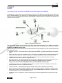
Congratulations on the purchase of your new Wireless Access Point. The Wireless Access Point links your 802.11g or
802.11b Wireless Stations to your wired LAN. The Wireless stations and devices on the wired LAN are then on the same
network, and can communicate with each other without regard for whether they are connected to the network via a
Wireless or wired connection.
Figure 1: Wireless Access Point
The auto-sensing capability of the Wireless Access Point allows packet transmission up to 54Mbps for maximum
throughput, or automatic speed reduction to lower speeds when the environment does not permit maximum throughput.
Features of your Wireless Access Point
The Wireless Access Point incorporates many advanced features, carefully designed to provide sophisticated functions
while being easy to use.
• Standards Compliant. The Wireless Router complies with the IEEE802.11g (DSSS) specifications for Wireless
LANs.
•
Supports both 802.11b and 802.11g Wireless Stations. The 802.11g standard provides for backward compatibility
with the 802.11b standard, so both 802.11b and 802.11g Wireless stations can be used simultaneously.
•
108Mbps Wireless Connections. On both the 2.4GHz (802.11b & 802.11g) and 5GHz (802.11a) bands,
108Mbps connections are available to compatible clients.
•
Bridge Mode Support. The Wireless Access Point can operate in Bridge Mode, connecting to another Access
Point. Both PTP (Point to Point) and PTMP (Point to Multi-Point) Bridge modes are supported.
And you can even use both Bridge Mode and Access Point Mode simultaneously!
•
Client/Repeater Access Point. The Wireless Access Point can operate as a Client or Repeater Access Point,
sending all traffic received to another Access Point.
•
Simple Configuration. If the default settings are unsuitable, they can be changed quickly and easily.
•
DHCP Client Support. Dynamic Host Configuration Protocol provides a dynamic IP address to PCs and other
devices upon request. The Wireless Access Point can act as a DHCP Client, and obtain an IP address and
related information from your existing DHPC Server.
•
Upgradeable Firmware. Firmware is stored in a flash memory and can be upgraded easily, using only your Web
Browser.
Page 4 of 93
Security Features
•
Security Profiles. For maximum flexibility, wireless security settings are stored in Security Profiles. Up to 8
Security profiles can be defined, and up to 4 used as any time.
•
Multiple SSIDs. Because each Security Profile has it own SSID, and up to 4 Security Profiles can be active
simultaneously, multiple SSIDs are supported. Different clients can connect to the Wireless Access Point
using different SSIDs, with different security settings.
•
Multiple SSID Isolation. If desired, PCs and devices connecting using different SSIDs can be isolated from
each other.
•
VLAN Support. The 802.1Q VLAN standard is supported, allowing traffic from different sources to be
segmented. Combined with the multiple SSID feature, this provides a powerful tool to control access to your
LAN.
•
WEP support. Support for WEP (Wired Equivalent Privacy) is included. Both 64 Bit and 128 Bit keys are
supported.
•
WPA support. Support for WPA is included. WPA is more secure than WEP, and should be used if possible.
Both TKIP and AES encryption methods are supported.
•
802.1x Support. Support for 802.1x mode is included, providing for the industrial-strength wireless security of
802.1x authentication and authorization.
•
Radius Client Support. The Wireless Access Point can login to your existing Radius Server (as a Radius client).
•
Radius MAC Authentication. You can centralize the checking of Wireless Station MAC addresses by using a
Radius Server.
•
Rogue AP Detection. The Wireless Access Point can detect unauthorized (Rouge) Access Points on your LAN.
•
Access Control. The Access Control feature can check the MAC address of Wireless clients to ensure that only
trusted Wireless Stations can use the Wireless Access Point to gain access to your LAN.
•
Password - protected Configuration. Optional password protection is provided to prevent unauthorized users
from modifying the configuration data and settings.
Advanced Features
•
Auto Configuration. The Wireless Access Point can perform self-configuration by copying the configuration data
from another Access Point. This feature is enabled by default.
•
Auto Update. The Wireless Access Point can automatically update its firmware, by downloading and installing
new firmware from your FTP server.
•
Command Line Interface. If desired, the command line interface (CLI) can be used for configuration. This
provides the possibility of creating scripts to perform common configuration changes.
•
NetBIOS & WINS Support. Support for both NetBIOS broadcast and WINS (Windows Internet Naming Service)
allows the Wireless Access Point to easily fit into your existing Windows network.
•
Radius Accounting Support. If you have a Radius Server, you can use it to provide accounting data on Wireless
clients.
•
Syslog Support. If you have a Syslog Server, the Wireless Access Point can send its log data to your Syslog
Server.
•
•
•
SNMP Support. SNMP (Simple Network Management Protocol) is supported, allowing you to use a SNMP
program to manage the Wireless Access Point.
UAM Support. The Wireless Access Point supports UAM (Universal Access Method), making it suitable for use
in Internet cafes and other sites where user access time must be accounted for.
WDS Support. Support for WDS (Wireless Distribution System) allows the Wireless Access Point to act as a
Wireless Bridge. Both Point-to-Point and Multi-Point Bridge modes are supported.
Page 5 of 93
Package Contents
The following items should be included:
• Wireless Access Point
If any of the above items are damaged or missing, please contact your dealer immediately.
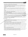
Physical Details
Front Panel LEDs
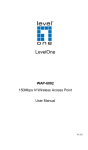
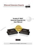
Figure 2: Front Panel
Status
Power
LAN
Wireless
LAN
On - Error condition.
Off - Normal operation.
Blinking - During start up, and when the Firmware is being upgraded.
On - Normal operation.
Off - No power
On - The LAN (Ethernet) port is active.
Off - No active connection on the LAN (Ethernet) port.
Flashing - Data is being transmitted or received via the corresponding
LAN (Ethernet) port.
On - Idle
Off - Error- Wireless connection is not available.
Flashing - Data is being transmitted or received via the Wireless
access point. Data includes "network traffic" as well as user data.
Page 6 of 93
Rear Panel
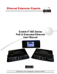
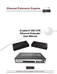
Figure 3 Rear Panel
Antenna
Console port
Reset Button
One antenna (aerial) is supplied. Best results are usually obtained
with the antenna in a vertical position.
DB9 female RS232 port.
This button has two (2) functions:
• Reboot. When pressed and released, the Wireless Access
Point will reboot (restart).
•
Ethernet
Power port
Reset to Factory Defaults. This button can also be used to
clear ALL data and restore ALL settings to the factory
default values.
To Clear All Data and restore the factory default values:
1. Power Off the Access Point
2. Hold the Reset Button down while you Power On the Access
Point.
3. Continue holding the Reset Button until the Status (Red)
LED blinks TWICE.
4. Release the Reset Button.
The factory default configuration has now been restored,
and the Access Point is ready for use.
Use a standard LAN cable (RJ45 connectors) to connect this port to
a 10BaseT or 100BaseT hub on your LAN.
Connect the supplied power adapter here.
Page 7 of 93
Chapter 3
Access Point Setup
This Chapter provides details of the Setup process for Basic Operation of your Wireless Access
Point.
Overview
This chapter describes the setup procedure to make the Wireless Access Point a valid device on your LAN, and to
function as an Access Point for your Wireless Stations.
Wireless Stations may also require configuration. For details, see Chapter 4 - Wireless Station Configuration.
The Wireless Access Point can be configured using either the supplied Windows utility or your Web Browser
Setup using the Windows Utility
A simple Windows setup utility is supplied on the CD-ROM. This utility can be used to assign a suitable IP address to the
Wireless Access Point. Using this utility is recommended, because it can locate the Wireless Access Point even if it has
an invalid IP address.
Installation
5. Insert the supplied CD-ROM in your drive.
6. If the utility does not start automatically, run the SETUP program in the root folder.
7. Follow the prompts to complete the installation.
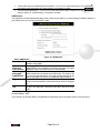
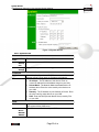
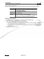
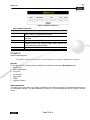
Main Screen
•
Start the program by using the icon created by the setup program.
•
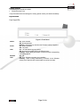
When run, the program searches the network for all active Wireless Access Points, then lists them on screen,
as shown by the example below.
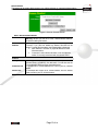
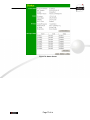
Figure 4: Management utility Screen
Wireless Access Points
The main panel displays a list of all Wireless Access Points found on the network. For each Access Point, the following
data is shown:
Server Name
IP address
MAC Address
IEEE Standard
FW Version
The Server Name is shown on a sticker on the base of the device.
The IP address for the Wireless Access Point.
The hardware or physical address of the Wireless Access Point.
The wireless standard or standards used by the Wireless Access
Point (e.g. 802.11b, 802.11g)
The current Firmware version installed in the Wireless Access Point.
Page 8 of 93
Description
Any extra information for the Wireless Access Point, entered by the
administrator.
Note: If the desired Wireless Access Point is not listed, check that the device is installed and ON, then update the list by
clicking the Refresh button.
Buttons
Refresh
Detail Info
Web Management
Set IP Address
Exit
Click this button to update the Wireless Access Point device
listing after changing the name or IP Address.
When clicked, additional information about the selected Access
Point will be displayed.
Use this button to connect to the Wireless Access Point's Webbased management interface.
Click this button if you want to change the IP Address of the
Wireless Access Point.
Exit the Management utility program by clicking this button.
Page 9 of 93
Setup Procedure
8. Select the desired Wireless Access Point.
9. Click the Set IP Address button.
10. If prompted, enter the user name and password. The default values are admin for the User Name, and
password for the Password.
11. Ensure the IP address, Network Mask, and Gateway are correct for your LAN. Save any changes.
12. Click the Web Management button to connect to the selected Wireless Access Point using your Web
Browser. If prompted, enter the User Name and Password again.
13. Check the following screens, and configure as necessary for your environment. Use the on-line help if
necessary.
The later sections in this Chapter also provides more details about each of these screens.
•
Access Control - MAC level access control.
•
Security Profiles - Wireless security.
•
System - Identification, location, and Network settings
• Wireless - Basic & Advanced
14. You may also wish to set the admin password and administration connection options. These are on the Admin
Login screen accessed from the Management menu. See Chapter 6 for details of the screens and features
available on the Management menu.
15. Use the Apply/Restart button on the menu to apply your changes and restart the Wireless Access Point.
Setup is now complete.
Wireless stations must now be set to match the Wireless Access Point. See Chapter 4 for details.
Setup using a Web Browser
Your Browser must support JavaScript. The configuration program has been tested on the following browsers:
• Netscape V4.08 or later
•
Internet Explorer V4 or later
Setup Procedure
Before commencing, install the Wireless Access Point in your LAN, as described previously.
16. Check the Wireless Access Point to determine its Default Name. This is shown on a label on the base or rear,
and is in the following format:
SCxxxxxx
Where xxxxxx is a set of 6 Hex characters ( 0 ~ 9, and A ~ F ).
17. Use a PC which is already connected to your LAN, either by a wired connection or another Access Point.
•
Until the Wireless Access Point is configured, establishing a Wireless connection to it may be not
possible.
•
If your LAN contains a Router or Routers, ensure the PC used for configuration is on the same LAN
segment as the Wireless Access Point.
18. Start your Web browser.
19. In the Address box, enter HTTP:// and the Default Name of the Wireless Access Point
e.g.
HTTP://SC2D631A
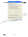
20. You should then see a login prompt, which will ask for a User Name and Password.
Enter admin for the User Name, and password for the Password.
These are the default values. The password can and should be changed. Always enter the current user name
and password, as set on the Admin Login screen.
Page 10 of 93
Figure 5: Password Dialog
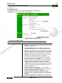
21. You will then see the Status screen, which displays the current settings and status. No data input is possible
on this screen. See Chapter 5 for details of the Status screen.
From the menu, check the following screens, and configure as necessary for your environment. Details of these
screens and settings are described in the following sections of this chapter.
•
Access Control - MAC level access control.
•
Security Profiles - Wireless security.
•
System - Identification, location, and Network settings
• Wireless - Basic & Advanced
22. You may also wish to set the admin password and administration connection options. These are on the Admin
Login screen accessed from the Management menu. See Chapter 6 for details of the screens and features
available on the Management menu.
23. Use the Apply/Restart button on the menu to apply your changes and restart the Wireless Access Point.
Setup is now complete.
Wireless stations must now be set to match the Wireless Access Point. See Chapter 4 for details.
If you can't connect:
It is likely that your PC’s IP address is incompatible with the Wireless Access
Point’s IP address. This can happen if your LAN does not have a DHCP Server.
The default IP address of the Wireless Access Point is 192.168.0.228, with a
Network Mask of 255.255.255.0.
If your PC’s IP address is not compatible with this, you must change your PC’s
IP address to an unused value in the range 192.168.0.1 ~ 192.168.0.254, with a
Network Mask of 255.255.255.0. See Appendix C - Windows TCP/IP for
details for this procedure.
Page 11 of 93
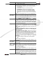
Access Control
This feature can be used to block access to your LAN by unknown or untrusted wireless stations.
Click Access Control on the menu to view a screen like the following.
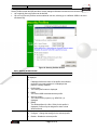
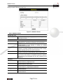
Figure 6: Access Control Screen
Data - Access Control Screen
Enable
Trusted
Stations
Use this checkbox to Enable or Disable this feature as desired.
Warning ! Ensure your own PC is in the "Trusted Wireless Stations"
list before enabling this feature.
This table lists any Wireless Stations you have designated as
"Trusted". If you have not added any stations, this table will be
empty. For each Wireless station, the following data is displayed:
• MAC Address - the MAC or physical address of each
Wireless station.
•
Connected - this indicates whether or not the Wireless
station is currently associates with this Access Point.
Buttons
Modify List
Read from File
Write to File
To change the list of Trusted Stations (Add, Edit, or Delete a
Wireless Station or Stations), click this button. You will then see the
Trusted Wireless Stations screen, described below.
To upload a list of Trusted Stations from a file on your PC, click this
button.
To download the current list of Trusted Stations from the Access
Point to a file on your PC, click this button.
Page 12 of 93
Trusted Wireless Stations
To change the list of trusted wireless stations, use the Modify List button on the Access Control screen. You will see a
screen like the sample below.
Figure 7: Trusted Wireless Stations
Data - Trusted Wireless Stations
Trusted
Stations
Other
Stations
Name
Wireless
Wireless
Address
This lists any Wireless Stations which you have designated as
“Trusted”.
This list any Wireless Stations detected by the Access Point,
which you have not designated as "Trusted".
The name assigned to the Trusted Wireless Station. Use this
when adding or editing a Trusted Station.
The MAC (physical) address of the Trusted Wireless Station.
Use this when adding or editing a Trusted Station.
Buttons
<<
Add a Trusted Wireless Station to the list (move from the "Other
Stations" list).
• Select an entry (or entries) in the "Other Stations" list,
and click the " << " button.
•
>>
Enter the Address (MAC or physical address) of the
wireless station, and click the "Add " button.
Delete a Trusted Wireless Station from the list (move to the
"Other Stations" list).
• Select an entry (or entries) in the "Trusted Stations" list.
•
Select All
Select None
Edit
Add
Click the " >> " button.
Select all of the Stations listed in the "Other Stations" list.
De-select any Stations currently selected in the "Other Stations"
list.
To change an existing entry in the "Trusted Stations" list,
select it and click this button.
24. Select the Station in the "Trusted Station" list.
25. Click the "Edit" button. The address will be copied to the
"Address" field, and the "Add" button will change to
"Update".
26. Edit the address (MAC or physical address) as required.
27. Click "Update" to save your changes.
To add a Trusted Station which is not in the "Other Wireless
Stations" list, enter the required data and click this button.
Page 13 of 93
Clear
Clear the Name and Address fields.
Security Profiles
Security Profiles contain the SSID and all the security settings for Wireless connections to this Access Point.
• Up to eight (8) Security Profiles can be defined.
•
Up to four (4) Security Profiles can be enabled at one time, allowing up to 4 different SSIDs to be used
simultaneously.
Figure 8: Security Profiles Screen
Data - Security Profiles Screen
Profile
Profile List
Buttons
All available profiles are listed. For each profile, the following data
is displayed:
• *
If displayed before the name of the profile, this indicates
the profile is currently enabled. If not displayed, the
profile is currently disabled.
•
Profile Name
The current profile name is displayed.
•
[SSID]
The current SSID associated with this profile.
•
Security System
The current security system (e.g. WPA-PSK ) is
displayed.
•
[Band]
The Wireless Band (2.4 GHz, 5GHz) for this profile is
displayed. Profiles may be assigned to either or both
Wireless Bands.
•
Enable - Enable the selected profile.
•
Configure - Change the settings for the selected profile.
•
Disable - Disable the selected profile.
Page 14 of 93
Primary Profile
802.11b/g AP Mode
802.11b/g
Mode
Bridge
Select the primary profile for 802.11b and 802.11g (2.4 GHz
band) AP mode. Only enabled profiles are listed. The SSID
associated with this profile will be broadcast if the "Broadcast
SSID" setting on the Basic screen is enabled.
Select the primary profile for 802.11b and 802.11g (2.4 GHz
band) Bridge Mode. This setting determines the SSID and
security settings used for the Bridge connection to the remote
AP.
Isolation
None
Isolate all
Use VLAN
If this option is selected, wireless clients using different profiles
(different SSIDs) are not isolated from each other, so they will be
able to communicate with each other.
If this option is selected, wireless clients using different profiles
(different SSIDs) are isolated from each other, so they will NOT
be able to communicate with each other. They will still be able to
communicate with other clients using the same profile, unless the
"Wireless Separation" setting on the "Advanced" screen has
been enabled.
This option is only useful if the hubs/switches on your LAN
support
the
VLAN
(802.1Q)
standard.
When VLAN is used, you must select the desired VLAN for each
security profile when configuring the profile. (If VLAN is not
selected, the VLAN setting for each profile is ignored.)
Click the "Configure VLAN" button to configure the IDs used by
each VLAN.
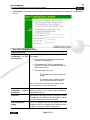
Security Profile Screen
This screen is displayed when you select a Profile on the Security Profiles screen, and click the Configure button.
Figure 9: Security Profile Screen
Profile Data
Enter the desired settings for each of the following:
Enter a suitable name for this profile.
Profile Name
Enter the desired SSID. Each profile must have a unique SSID.
SSID
Select the wireless band or bands for this profile. If your Wireless
Wireless Band
Access Point only has a single band, then only 1 option is
available.
Page 15 of 93
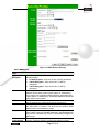
Security Settings
Select the desired option, and then enter the settings for the selected method.
The available options are:
• None - No security is used. Anyone using the correct SSID can connect to your network.
•
WEP - The 802.11b standard. Data is encrypted before transmission, but the encryption system is not very
strong.
•
WPA-PSK - Like WEP, data is encrypted before transmission. WPA is more secure than WEP, and should be
used if possible. The PSK (Pre-shared Key) must be entered on each Wireless station. The 256Bit encryption
key is derived from the PSK, and changes frequently.
•
WPA-802.1x - This version of WPA requires a Radius Server on your LAN to provide the client authentication
according to the 802.1x standard. Data transmissions are encrypted using the WPA standard.
If this option is selected:
•
•
This Access Point must have a "client login" on the Radius Server.
•
Each user must have a "user login" on the Radius Server.
•
Each user's wireless client must support 802.1x and provide the login data when required.
•
All data transmission is encrypted using the WPA standard. Keys are automatically generated, so no key
input is required.
802.1x - This uses the 802.1x standard for client authentication, and WEP for data encryption. If possible, you
should use WPA-802.1x instead, because WPA encryption is much stronger than WEP encryption.
If this option is selected:
•
This Access Point must have a "client login" on the Radius Server.
•
Each user must have a "user login" on the Radius Server.
•
Each user's wireless client must support 802.1x and provide the login data when required.
•
All data transmission is encrypted using the WEP standard. You only have to select the WEP key size;
the WEP key is automatically generated.
Page 16 of 93
Security Settings - None
Figure 10: Wireless Security - None
No security is used. Anyone using the correct SSID can connect to your network.
The only settings available from this screen are Radius MAC Authentication and UAM (Universal Access Method).
Radius MAC Authentication
Radius MAC Authentication provides for MAC address checking which is centralized on your Radius server. If you don't
have a Radius Server, you cannot use this feature.
Using MAC authentication
28. Ensure the Wireless Access Point can login to your Radius Server.
•
Add a RADIUS client on the RADIUS server, using the IP address or name of the Wireless Access Point,
and the same shared key as entered on the Wireless Access Point.
•
Ensure the Wireless Access Point has the correct address, port number, and shared key for login to your
Radius Server. These parameters are entered either on the Security page, or the Radius-based MAC
authentication sub-screen, depending on the security method used.
• On the Access Point, enable the Radius-based MAC authentication feature on the screen below.
29. Add Users on the Radius server as required. The username must be the MAC address of the Wireless client
you wish to allow, and the password must be blank.
30. When clients try to associate with the Access Point, their MAC address is passed to the Radius Server for
authentication.
•
If successful, “xx:xx:xx:xx:xx:xx MAC authentication” is entered in the log, and client station status would
show as “authenticated” on the station list table;
•
If not successful, “xx:xx:xx:xx:xx:xx MAC authentication failed” is entered in the log,, and station status is
shown as “authenticating” on the station list table.
Page 17 of 93
Radius-based MAC authentication Screen
This screen will look different depending on the current security setting. If you have already provided the address of your
Radius server, you won't be prompted for it again. Otherwise, you must enter the details of your Radius Server on this
screen.
Figure 11: Radius-based MAC Authentication Screen
Data - Radius-based MAC Authentication Screen
Enable ...
Radius
Server
Address
Radius Port
Client
Name
Login
Shared Key
WEP Key
WEP Key Index
Enable this if you wish to Radius-based MAC authentication.
If this field is visible, enter the name or IP address of the Radius
Server on your network.
If this field is visible, enter the port number used for connections to
the Radius Server.
If this field is visible, it displays the name used for the Client Login
on the Radius Server. This Login name must be created on the
Radius Server.
If this field is visible, it is used for the Client Login on the Radius
Server. Enter the key value to match the value on the Radius
Server.
If this field is visible, it is for the WEP key used to encrypt data
transmissions to the Radius Server. Enter the desired key value in
HEX, and ensure the Radius Server has the same value.
If this field is visible, select the desired key index. Any value can be
used, provided it matches the value on the Radius Server.
Page 18 of 93
UAM
UAM (Universal Access Method) is intended for use in Internet cafes, Hot Spots, and other sites where the Access Point
is used to provide Internet Access.
If enabled, then HTTP (TCP, port 80) connections are checked. (UAM only works on HTTP connections; all other traffic
is ignored.) If the user has not been authenticated, Internet access is blocked, and the user is re-directed to another web
page. Typically, this web page is on your Web server, and explains how to pay for and obtain Internet access.
To use UAM, you need a Radius Server for Authentication. The "Radius Server Setup" must be completed before you
can use UAM. The required setup depends on whether you are using “Internal” or “External” authentication.
• Internal authentication uses the web page built into the Wireless Access Point.
•
External authentication uses a web page on your Web server. Generally, you should use External
authentication, as this allows you to provide relevant and helpful information to users.
UAM authentication - Internal
31. Ensure the Wireless Access Point can login to your Radius Server.
•
Add a RADIUS client on RADIUS server, using the IP address or name of the Wireless Access Point, and
the same shared key as entered on the Wireless Access Point.
•
32.
33.
34.
35.
36.
Ensure the Wireless Access Point has the correct address, port number, and shared key for login to your
Radius Server. These parameters are entered either on the Security page, or the UAM sub-screen,
depending on the security method used.
Add users on your RADIUS server as required, and allow access by these users.
Client PCs must have the correct Wireless settings in order to associate with the Wireles Access Point.
When an associated client tries to use HTTP (TCP, port 80) connections, they will be re-directed to a user
login page.
The client (user) must then enter the user name and password, as defined on the Radius Server. (You must
provide some system to let users know the correct name and password to use.)
If the user name and password is correct, Internet access is allowed.
Otherwise, the user remains on the login page.
•
Clients which pass the authentication are listed as “xx:xx:xx:xx:xx:xx WEB authentication” in the log table,
and station status would show as “Authenticated” on the station list table.
•
If a client fails authentication, “xx:xx:xx:xx:xx:xx WEB authentication failed” shown in the log, and station
status is shown as “Authenticating” on the station list table.
UAM authentication - External
37. Ensure the Wireless Access Point can login to your Radius Server.
•
Add a RADIUS client on RADIUS server, using the IP address or name of the Wireless Access Point, and
the same shared key as entered on the Wireless Access Point.
•
38.
39.
40.
41.
42.
43.
44.
Ensure the Wireless Access Point has the correct address, port number, and shared key for login to your
Radius Server. These parameters are entered either on the Security page, or the UAM sub-screen,
depending on the security method used.
On your Web Server, create a suitable welcome page.
The welcome page must have a link or button to allow the user to input their user name and password
on the uamlogon.htm page on the Access Point.
On the Access Point’s UAM screen, select External Web-based Authentication, and enter the URL for the
welcome page on your Web server.
Add users on your RADIUS server as required, and allow access by these users.
Client PCs must have the correct Wireless settings in order to associate with the Wireless Access Point.
When an associated client tries to use HTTP (TCP, port 80) connections, they will be re-directed to the
welcome page on your Web Server. They must then click the link or button in order to reach the Access
Point’s login page.
The client (user) must then enter the user name and password, as defined on the Radius Server. (You must
provide some system to let users know the correct name and password to use.)
If the user name and password is correct, Internet access is allowed.
Otherwise, the user remains on the login page.
Page 19 of 93
•
Clients which pass the authentication are listed as “xx:xx:xx:xx:xx:xx WEB authentication” in the log table,
and station status would show as “Authenticated” on the station list table.
•
If a client fails authentication, “xx:xx:xx:xx:xx:xx WEB authentication failed” is shown in the log, and station
status is shown as “Authenticating” on the station list table.
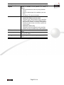
UAM Screen
The UAM screen will look different depending on the current security setting. If you have already provided the address of
your Radius server, you won't be prompted for it again.
Figure 12: UAM Screen
Data - UAM Screen
Enable
Internal
Web-based
Authentication
External
Web-based
Authentication
Login URL
Login
URL
Failure
Enable this if you wish to use this feature. See the section above for
details of using UAM.
If selected, then when a user first tries to access the Internet, they
will be blocked, and re-directed to the built-in login page. The logon
data is then sent to the Radius Server for authentication.
If selected, then when a user first tries to access the Internet, they
will be blocked, and re-directed to the URL below. This needs to be
on your own local Web Server. The page must also link back to the
built-in login page on this device to complete the login procedure.
Enter the URL of the page on your local Web Server you wish users
to see when they attempt to access the Internet, but are not logged
in.
Enter the URL of the page on your local Web Server you wish users
to see if their login fails. (This may be the same URL as the Login
URL).
Security Settings - WEP
This is the 802.11b standard. Data is encrypted before transmission, but the encryption system is not very strong.
Page 20 of 93
Figure 13: WEP Wireless Security
Data - WEP Screen
WEP
Data
Encryption
Authentication
Key Input
Key Value
Passphrase
Radius
MAC
Authentication
Select the desired option, and ensure your Wireless stations have
the same setting:
• 64 Bit Encryption - Keys are 10 Hex (5 ASCII) characters.
•
128 Bit Encryption - Keys are 26 Hex (13 ASCII)
characters.
•
152 Bit Encryption - Keys are 32 Hex (16 ASCII)
characters.
Normally, you can leave this at “Automatic”, so that Wireless
Stations can use either method ("Open System" or "Shared Key".).
If you wish to use a particular method, select the appropriate value "Open System" or "Shared Key". All Wireless stations must then be
set to use the same method.
Select "Hex" or "ASCII" depending on your input method. (All keys
are converted to Hex, ASCII input is only for convenience.)
Enter the key values you wish to use. The default key, selected by
the radio button, is required. The other keys are optional. Other
stations must have matching key values.
Use this to generate a key or keys, instead of entering them directly.
Enter a word or group of printable characters in the Passphrase box
and click the "Generate Key" button to automatically configure the
WEP Key(s).
The current status is displayed.
Click the "Configure" button to configure this feature if required.
Page 21 of 93
UAM
The current status is displayed.
Click the "Configure" button to configure this feature if required.
Page 22 of 93
Security Settings - WPA-PSK
Like WEP, data is encrypted before transmission. WPA is more secure than WEP, and should be used if possible. The
PSK (Pre-shared Key) must be entered on each Wireless station. The 256Bit encryption key is derived from the PSK,
and changes frequently.
Figure 14: WPA-PSK Wireless Security
Data - WPA-PSK Screen
WPA-PSK
Network Key
WPA Encryption
Enter the key value. Data is encrypted using a 256Bit key
derived from this key. Other Wireless Stations must use the
same key.
Select the desired option. Other Wireless Stations must use
the same method.
• TKIP - Unicast (point-to-point) transmissions are
encrypted using TKIP, and multicast (broadcast)
transmissions are not encrypted.
•
TKIP + 64 bit WEP - Unicast (point-to-point)
transmissions are encrypted using TKIP, and multicast
(broadcast) transmissions are encrypted using 64 bit
WEP.
•
TKIP + 128 bit WEP - Unicast (point-to-point)
transmissions are encrypted using TKIP, and multicast
(broadcast) transmissions are encrypted using 128 bit
WEP.
•
AES - CCMP - CCMP is the most common sub-type of
AES (Advanced Encryption System). Most systems will
simply say "AES". If selected, both Unicast (point-topoint) and multicast (broadcast) transmissions are
encrypted using AES.
•
AES - TKIP - If selected, Unicast (point-to-point) uses
Page 23 of 93
AES-CCMP and multicast (broadcast) transmissions
are encrypted using TKIP.
Pairwise Key Update
Key Lifetime
Group Key Update
Key Lifetime
Update Group key
when
any
membership
terminates
Radius
MAC
Authentication
UAM
This refers to the key used for point-to-point transmissions.
Enable this if you want the keys to be updated regularly.
This field determines how often Pairwise keys are dynamically
updated. Enter the desired value.
This refers to the key used for broadcast transmissions. Enable
this if you want the keys to be updated regularly.
This field determines how often the Group key is dynamically
updated. Enter the desired value.
If enabled, the Group key will be updated whenever any
member leaves the group or disassociates from the Access
Point.
The current status is displayed. This will always be "Disabled",
because Radius MAC Authentication is not available with
WPA-PSK. The Configure button for this feature will also be
disabled.
The current status is displayed. This will always be "Disabled",
because UAM is not available with WPA-PSK. The Configure
button for this feature will also be disabled.
Page 24 of 93
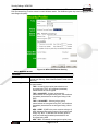
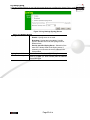
System Screen
Click System on the menu to view a screen like the following.
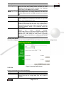
Figure 15: System Screen
Data - System Screen
Identification
Access
Name
Point
Enter a suitable name for this Access Point.
Descrip
tion
If desired, you can enter a description for the Access Point.
Country
Domain
Select the country or domain matching your current location.
IP Address
DHCP Client
Fixed
Select this option if you have a DHCP Server on your LAN, and you
wish the Access Point to obtain an IP address automatically.
If selected, the following data must be entered.
• IP Address - The IP Address of this device. Enter an
unused IP address from the address range on your LAN.
•
Subnet Mask - The Network Mask associated with the IP
Address above. Enter the value used by other devices on
your LAN.
•
Gateway - The IP Address of your Gateway or Router. Enter
the value used by other devices on your LAN.
•
DNS - Enter the DNS (Domain Name Server) used by PCs
on your LAN.
WINS
Enable WINS
WINS
Server
Name/IP
Address
If your LAN has a WINS server, you can enable this to have this
AP register with the WINS server.
Enter the name or IP address of your WINS server.
Page 25 of 93
Wireless Screens
There are two (2) configuration screens available:
• Basic Settings
•
Advanced
Basic Settings Screen
The settings on this screen must match the settings used by Wireless Stations.
Click Basic on the menu to view a screen like the following.
Figure 16: Basic Settings Screen
Data - Basic Settings Screen
Operation
Wireless Mode
Select the desired option:
• Disable - select this if for some reason you do not this AP to
transmit or receive at all.
•
802.11b and 802.11g - this is the default, and will allow
connections by both 802.11b and 802.1g wireless stations.
•
802.11b - if selected, only 802.11b connections are allowed.
802.11g wireless stations will only be able to connect if they
are fully backward-compatible with the 802.11b standard.
•
802.11g - only 802.11g connections are allowed. If you only
have 802.11g, selecting this option may provide a
performance improvement over using the default setting.
•
Dynamic Super 802.11g (108Mbps) - This uses Packet
Bursting, FastFrame, Compression, and Channel Bonding
(using 2 channels) to increase throughput. Only clients
supporting the "Atheros Super G" mode can connect at
108Mbps, and they will only use this speed when necessary.
However, this option is backward-compatible with 802.11b
and (standard) 802.11g.
•
Static Super 802.11g (108Mbps) - This uses Packet
Bursting, FastFrame, Compression, and Channel Bonding
(using 2 channels) to increase throughput.
Because "Channel Bonding" is always used, this
method is NOT compatible with 802.11b and (standard)
802.11g.
Only clients supporting the "Atheros Super G" mode can
connect at 108Mbps; they will always connect at this speed.
Page 26 of 93
AP Mode
Select this option only if all wireless stations support this
"Atheros Super G" mode.
Both Bridge mode and AP mode can be used simultaneously,
unless AP mode is "Client/Repeater". Select the desired AP mode:
• None (disable) - Disable AP mode. Use this if you want to
act a Bridge only.
•
•
Repeater
AP
MAC Address
Broadcast SSID
Bridge Mode
PTP Bridge AP
MAC Address
In PTMP mode,
only
allow
specified APs
Set PTMP APs
Access Point - operate as a normal Access Point
Client/Repeater - act as a client or repeater for another
Access Point. If selected, you must provide the address
(MAC address) of the other AP in the Repeater AP MAC
Address field. In this mode, all traffic is sent to the specified
AP.
Note: If using Client/Repeater mode, you cannot use Bridge Mode.
This is not required unless the AP Mode is "Client/Repeater". In this
mode, you must provide the MAC address of the other AP in this
field. You can either enter the MAC address directly, or, if the other
AP is on-line and broadcasting its SSID, you can click the "Select
AP" button and select from a list of available APs.
If
Disabled,
no
SSID
is
broadcast.
If enabled, you must select the security profile whose SSID is to be
broadcast. This can be done the "Security Profiles" screen. The
SSID will then be broadcast to all Wireless Stations. Stations which
have no SSID (or a "null" value) can then adopt the correct SSID for
connections to this Access Point.
Both Bridge mode and AP mode can be used simultaneously,
unless AP mode is "Client/Repeater". Select the desired Bridge
mode:
None (disable) - Disable Bridge mode. Use this if you want to act a
AP only.
Point-to-Point Bridge (PTP) - Bridge to a single AP. You must
provide the MAC address of the other AP in the PTP Bridge AP
MAC Address field.
Point-to-Multi-Point Bridge (PTMP) - Select this only if this AP is
the "Master" for a group of Bridge-mode APs. The other Bridgemode APs must be set to Point-to-Point Bridge mode, using this
AP's MAC address. They then send all traffic to this "Master".
If required, you can specify the MAC addresses of the APs which
are allowed to connect to this AP in PTMP mode. To specify the
allowed APs:
45. Enable the checkbox "In PTMP mode, only allow specified
APs".
Click the button "Set PTMP APs".
On the resulting sub-screen, enter the MAC addresses of the
allowed APs.
This is not required unless the Bridge Mode is "Point-to-Point Bridge
(PTP)". In this case, you must enter the MAC address of the other
AP in this field.
This is only functional if using Point-to-Multi-Point Bridge (PTMP)
mode. If enabled, you can specify the MAC addresses of the APs
which are allowed to connect to this AP. To specify the allowed APs:
46. Enable this checkbox
Click the button "Set PTMP APs".
On the resulting sub-screen, enter the MAC addresses of the
allowed APs.
Use this to open a sub-window where you can specify the MAC
addresses of the APs which are allowed to connect to this AP. This
is only functional if using Point-to-Multi-Point Bridge (PTMP) mode
and you have enabled the checkbox "In PTMP mode, only allow
specified APs".
Page 27 of 93
Parameters
Channel No
•
If "Automatic" is selected, the Access Point will select the
best available Channel.
•
Current
Channel No.
If you experience interference (shown by lost connections
and/or slow data transfers) you may need to experiment with
manually setting different channels to see which is the best.
This displays the current channel used by the Access Point.
Page 28 of 93
Advanced Settings
Clicking the Advanced link on the menu will result in a screen like the following.
Figure 17: Advanced Settings
Data - Advanced Settings Screen
Basic Rate
Basic Rate
The Basic Rate is used for broadcasting. It does not
determine the data transmission rate, which is determined by
the
"Mode"
setting
on
the
Basic
screen.
Select
the
desired
option.
Do NOT select the "802.11g" or "ODFM" options unless ALL
of your wireless clients support this. 802.11b clients will not be
able to connect to the Access Point if either of these modes is
selected.
Options
Wireless Separation
Worldwide
(802.11d)
Mode
If enabled, then each Wireless station using the Access Point
is invisible to other Wireless stations. In most business
situations, this setting should be Disabled.
Enable this setting if you wish to use this mode, and your
Wireless stations support this mode.
Parameters
Disassociated
Timeout
Fragmentatio
n
Beacon Interval
RTS/CTS
Threshold
Preamble Type
This determines how quickly a Wireless Station will be
considered "Disassociated" with this AP, when no traffic is
received. Enter the desired time period.
Enter the preferred setting between 256 and 2346. Normally,
this can be left at the default value.
Enter the preferred setting between 20 and 1000. Normally,
this can be left at the default value.
Enter the preferred setting between 256 and 2346. Normally,
this can be left at the default value.
Select the desired option. The default is "Long". The "Short"
setting takes less time when used in a good environment.
Page 29 of 93
Output Power Level
Antenna Selection
Select the desired power output. Higher levels will give a
greater range, but are also more likely to cause interference
with other devices.
If your Access Point has only 1 antenna, there is only 1 option
available. If your Access Point has 2 antennae, select the
option which gives the best results in your location.
802.11b
Protection
Type
Short Slot Time
Protection
Mode
Protection Rate
Select the desired option. The default is CTS-only.
Enable or disable this setting as required.
The Protection system is intended to prevent older 802.11b
devices from interfering with 802.11g transmissions. (Older
802.11b devices may not be able to detect that a 802.11g
transmission is in progress.) Normally, this should be left at
"Auto".
Select the desired option. The default is 11 Mbps.
Page 30 of 93
Chapter 4
PC and Server Configuration
This Chapter details the PC Configuration required for each PC on the local LAN.
Overview
All Wireless Stations need to have settings which match the Wireless Access Point. These settings depend on the mode
in which the Access Point is being used.
• If using WEP or WPA-PSK, it is only necessary to ensure that each Wireless station's settings match those of
the Wireless Access Point, as described below.
•
For WPA-802.1x and 802.1x modes, configuration is much more complex. The Radius Server must be
configured correctly, and setup of each Wireless station is also more complex.
Using WEP
For each of the following items, each Wireless Station must have the same settings as the Wireless Access Point.
Mode
SSID (ESSID)
On each PC, the mode must be set to Infrastructure.
This must match the value used on the Wireless Access Point.
The default value is wireless
Note! The SSID is case sensitive.
Wireless
Security
•
Each Wireless station must be set to use WEP data
encryption.
•
The Key size (64 bit, 128 bit, 152 bit) must be set to match the
Access Point.
•
The keys values on the PC must match the key values on the
Access Point.
Note:
On some systems, the key sizes may be shown as 40bit, 104bit, and
128bit instead of 64 bit, 128 bit and 152bit. This difference arises
because the key input by the user is 24 bits less than the key size
used for encryption.
Page 31 of 93
Using WPA-802.1x
This is the most secure and most complex system.
802.1x mode provides greater security and centralized management, but it is more complex to configure.
Wireless Station Configuration
For each of the following items, each Wireless Station must have the same settings as the Wireless Access Point.
Mode
SSID (ESSID)
802.1x
Authentication
802.1x
Encryption
On each PC, the mode must be set to Infrastructure.
This must match the value used on the Wireless Access Point.
The default value is wireless
Note! The SSID is case sensitive.
Each client must obtain a Certificate which is used for authentication
for the Radius Server.
Typically, EAP-TLS is used. This is a dynamic key system, so keys do
NOT have to be entered on each Wireless station.
However, you can also use a static WEP key (EAP-MD5); the
Wireless Access Point supports both methods simultaneously.
Radius Server Configuration
If using WPA-802.1x mode, the Radius Server on your network must be configured as follow:
• It must provide and accept Certificates for user authentication.
•
•
There must be a Client Login for the Wireless Access Point itself.
•
The Wireless Access Point will use its Default Name as its Client Login name. (However, your Radius
server may ignore this and use the IP address instead.)
•
The Shared Key, set on the Security Screen of the Access Point, must match the Shared Secret value on
the Radius Server.
Encryption settings must be correct.
Page 32 of 93
802.1x Server Setup (Windows 2000 Server)
This section describes using Microsoft Internet Authentication Server as the Radius Server, since it is the most common
Radius Server available that supports the EAP-TLS authentication method.
The following services on the Windows 2000 Domain Controller (PDC) are also required:
• dhcpd
•
dns
•
rras
•
webserver (IIS)
•
Radius Server (Internet Authentication Service)
•
Certificate Authority
Windows 2000 Domain Controller Setup
47. Run dcpromo.exe from the command prompt.
48. Follow all of the default prompts, ensure that DNS is installed and enabled during installation.
Services Installation
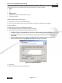
49. Select the Control Panel - Add/Remove Programs.
50. Click Add/Remove Windows Components from the left side.
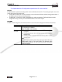
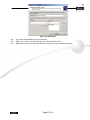
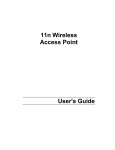
51. Ensure that the following components are activated (selected):
•
Certificate Services. After enabling this, you will see a warning that the computer cannot be renamed and
joined after installing certificate services. Select Yes to select certificate services and continue
•
World Wide Web Server. Select World Wide Web Server on the Internet Information Services (IIS)
component.
•
From the Networking Services category, select Dynamic Host Configuration Protocol (DHCP), and
Internet Authentication Service (DNS should already be selected and installed).
Figure 18: Components Screen
52. Click Next.
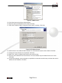
53. Select the Enterprise root CA, and click Next.
Page 33 of 93
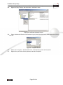
Figure 19: Certification Screen
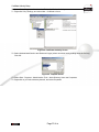
54. Enter the information for the Certificate Authority, and click Next.
Figure 20: CA Screen
55. Click Next if you don't want to change the CA's configuration data.
56. Installation will warn you that Internet Information Services are running, and must be stopped before
continuing. Click Ok, then Finish.
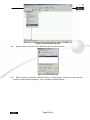
DHCP server configuration
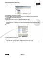
57. Click on the Start - Programs - Administrative Tools - DHCP
58. Right-click on the server entry as shown, and select New Scope.
Page 34 of 93
Figure 21: DHCP Screen
59. Click Next when the New Scope Wizard Begins.
60. Enter the name and description for the scope, click Next.
61. Define the IP address range. Change the subnet mask if necessary. Click Next.
Figure 22:IP Address Screen
62.
63.
64.
65.
Add exclusions in the address fields if required. If no exclusions are required, leave it blank. Click Next.
Change the Lease Duration time if preferred. Click Next.
Select Yes, I want to configure these options now, and click Next.
Enter the router address for the current subnet. The router address may be left blank if there is no router.
Click Next.
66. For the Parent domain, enter the domain you specified for the domain controller setup, and enter the server's
address for the IP address. Click Next.
Page 35 of 93
Figure 23: DNS Screen
67. If you don't want a WINS server, just click Next.
68. Select Yes, I want to activate this scope now. Click Next, then Finish.
69. Right-click on the server, and select Authorize. It may take a few minutes to complete.
Page 36 of 93
Certificate Authority Setup
70. Select Start - Programs - Administrative Tools - Certification Authority.
71. Right-click Policy Settings, and select New - Certificate to Issue.
Figure 24: Certificate Authority Screen
72. Select Authenticated Session and Smartcard Logon (select more than one by holding down the Ctrl key).
Click OK.
Figure 25: Template Screen
73. Select Start - Programs - Administrative Tools - Active Directory Users and Computers.
74. Right-click on your active directory domain, and select Properties.
Page 37 of 93
Figure 26: Active Directory Screen
75. Select the Group Policy tab, choose Default Domain Policy then click Edit.
Figure 27: Group Policy Tab
76. Select Computer Configuration - Windows Settings - Security Settings - Public Key Policies, right-click
Automatic Certificate Request Settings - New - Automatic Certificate Request.
Page 38 of 93
Figure 28: Group Policy Screen
77. When the Certificate Request Wizard appears, click Next.
78. Select Computer, then click Next.
Figure 29: Certificate Template Screen
79. Ensure that your certificate authority is checked, then click Next.
80. Review the policy change information and click Finish.
81. Click Start - Run, type cmd and press enter.
Enter secedit /refreshpolicy machine_policy
This command may take a few minutes to take effect.
Page 39 of 93
Internet Authentication Service (Radius) Setup
82. Select Start - Programs - Administrative Tools - Internet Authentication Service
83. Right-click on Clients, and select New Client.
Figure 30: Service Screen
84. Enter a name for the access point, click Next.
85. Enter the address or name of the Wireless Access Point, and set the shared secret, as entered on the
Security Settings of the Wireless Access Point.
86. Click Finish.
87. Right-click on Remote Access Policies, select New Remote Access Policy.
88. Assuming you are using EAP-TLS, name the policy eap-tls, and click Next.
89. Click Add...
If you don't want to set any restrictions and a condition is required, select Day-And-Time-Restrictions, and
click Add...
90.
Figure 31: Attribute Screen
91. Click Permitted, then OK. Select Next.
92. Select Grant remote access permission. Click Next.
93. Click Edit Profile... and select the Authentication tab. Enable Extensible Authentication Protocol, and select
Smart Card or other Certificate. Deselect other authentication methods listed. Click OK.
Page 40 of 93
Figure 32: Authentication Screen
94. Select No if you don't want to view the help for EAP. Click Finish.
Page 41 of 93
Remote Access Login for Users
95. Select Start - Programs - Administrative Tools- Active Directory Users and Computers.
96. Double click on the user who you want to enable.
97. Select the Dial-in tab, and enable Allow access. Click OK.
Figure 33: Dial-in Screen
Page 42 of 93
802.1x Client Setup on Windows XP
Windows XP ships with a complete 802.1x client implementation. If using Windows 2000, you can install SP3 (Service
Pack 3) to gain the same functionality.
If you don't have either of these systems, you must use the 802.1x client software provided with your wireless adapter.
Refer to your vendor's documentation for setup instructions.
The following instructions assume that:
• You are using Windows XP
•
You are connecting to a Windows 2000 server for authentication.
•
You already have a login (User name and password) on the Windows 2000 server.
Client Certificate Setup
98. Connect to a network which doesn't require port authentication.
99. Start your Web Browser. In the Address box, enter the IP address of the Windows 2000 Server, followed by
/certsrv
e.g
http://192.168.0.2/certsrv
100.
You will be prompted for a user name and password. Enter the User name and Password assigned to
you by your network administrator, and click OK.
Figure 34: Connect Screen
101.
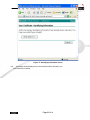
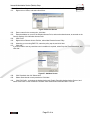
On the first screen (below), select Request a certificate, click Next.
Page 43 of 93
Figure 35: Wireless CA Screen
102.
103.
Select User certificate request and select User Certificate, the click Next.
Page 44 of 93
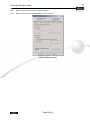
Figure 36: Request Type Screen
104.
Click Submit.
Page 45 of 93
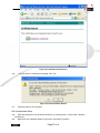
Figure 37: Identifying Information Screen
105.
A message will be displayed, then the certificate will be returned to you.
Click Install this certificate.
Page 46 of 93
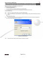
Figure 38:Certificate Issued Screen
106.
. You will receive a confirmation message. Click Yes.
Figure 39: Root Certificate Screen
107.
Certificate setup is now complete.
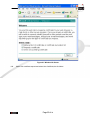
802.1x Authentication Setup
108.
Open the properties for the wireless connection, by selecting Start - Control Panel - Network
Connections.
109.
Right Click on the Wireless Network Connection, and select Properties.
Page 47 of 93
110.
Select the Authentication Tab, and ensure that Enable network access control using IEEE 802.1X is
selected, and Smart Card or other Certificate is selected from the EAP type.
Figure 40: Authentication Tab
Encryption Settings
The Encryption settings must match the APs (Access Points) on the Wireless network you wish to join.
• Windows XP will detect any available Wireless networks, and allow you to configure each network
independently.
•
Your network administrator can advise you of the correct settings for each network. 802.1x networks typically
use EAP-TLS. This is a dynamic key system, so there is no need to enter key values.
Enabling Encryption
To enable encryption for a wireless network, follow this procedure:
111.
Click on the Wireless Networks tab.
Page 48 of 93
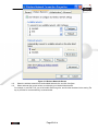
Figure 41: Wireless Networks Screen
112.
Select the wireless network from the Available Networks list, and click Configure.
113.
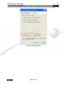
Select and enter the correct values, as advised by your Network Administrator.
For example, to use EAP-TLS, you would enable Data encryption, and click the checkbox for the setting The
key is provided for me automatically, as shown below.
Page 49 of 93
Figure 42: Properties Screen
Setup for Windows XP and 802.1x client is now complete.
Page 50 of 93
Using 802.1x Mode (without WPA)
This is very similar to using WPA-802.1x.
The only difference is that on your client, you must NOT enable the setting The key is provided for me automatically.
Instead, you must enter the WEP key manually, ensuring it matches the WEP key used on the Access Point.
Figure 43: Properties Screen
Page 51 of 93
Using WPA-PSK
For each of the following items, each Wireless Station must have the same settings as the Wireless Access Point.
Mode
SSID (ESSID)
Wireless
Security
On each PC, the mode must be set to Infrastructure.
This must match the value used on the Wireless Access Point.
The default value is wireless
Note! The SSID is case sensitive.
On each client, Wireless security must be set to WPA-PSK.
• The Pre-shared Key entered on the Access Point must also
be entered on each Wireless client.
•
The Encryption method (e.g. TKIP, AES) must be set to
match the Access Point.
Page 52 of 93
Using WPA-802.1x
This is the most secure and most complex system.
802.1x mode provides greater security and centralized management, but it is more complex to configure.
Wireless Station Configuration
For each of the following items, each Wireless Station must have the same settings as the Wireless Access Point.
Mode
SSID (ESSID)
802.1x
Authentication
802.1x
Encryption
On each PC, the mode must be set to Infrastructure.
This must match the value used on the Wireless Access Point.
The default value is wireless
Note! The SSID is case sensitive.
Each client must obtain a Certificate which is used for authentication
for the Radius Server.
Typically, EAP-TLS is used. This is a dynamic key system, so keys do
NOT have to be entered on each Wireless station.
However, you can also use a static WEP key (EAP-MD5); the
Wireless Access Point supports both methods simultaneously.
Radius Server Configuration
If using WPA-802.1x mode, the Radius Server on your network must be configured as follow:
• It must provide and accept Certificates for user authentication.
•
•
There must be a Client Login for the Wireless Access Point itself.
•
The Wireless Access Point will use its Default Name as its Client Login name. (However, your Radius
server may ignore this and use the IP address instead.)
•
The Shared Key, set on the Security Screen of the Access Point, must match the Shared Secret value on
the Radius Server.
Encryption settings must be correct.
Page 53 of 93
802.1x Server Setup (Windows 2000 Server)
This section describes using Microsoft Internet Authentication Server as the Radius Server, since it is the most common
Radius Server available that supports the EAP-TLS authentication method.
The following services on the Windows 2000 Domain Controller (PDC) are also required:
• dhcpd
•
dns
•
rras
•
webserver (IIS)
•
Radius Server (Internet Authentication Service)
•
Certificate Authority
Windows 2000 Domain Controller Setup
114.
115.
Run dcpromo.exe from the command prompt.
Follow all of the default prompts, ensure that DNS is installed and enabled during installation.
Services Installation
116.
117.
118.
Select the Control Panel - Add/Remove Programs.
Click Add/Remove Windows Components from the left side.
Ensure that the following components are activated (selected):
•
Certificate Services. After enabling this, you will see a warning that the computer cannot be renamed and
joined after installing certificate services. Select Yes to select certificate services and continue
•
World Wide Web Server. Select World Wide Web Server on the Internet Information Services (IIS)
component.
•
From the Networking Services category, select Dynamic Host Configuration Protocol (DHCP), and
Internet Authentication Service (DNS should already be selected and installed).
Figure 44: Components Screen
119.
120.
Click Next.
Select the Enterprise root CA, and click Next.
Page 54 of 93
Figure 45: Certification Screen
121.
Enter the information for the Certificate Authority, and click Next.
Figure 46: CA Screen
122.
Click Next if you don't want to change the CA's configuration data.
123.
Installation will warn you that Internet Information Services are running, and must be stopped before
continuing. Click Ok, then Finish.
DHCP server configuration
124.
125.
Click on the Start - Programs - Administrative Tools - DHCP
Right-click on the server entry as shown, and select New Scope.
Page 55 of 93
Figure 47: DHCP Screen
126.
127.
128.
Click Next when the New Scope Wizard Begins.
Enter the name and description for the scope, click Next.
Define the IP address range. Change the subnet mask if necessary. Click Next.
Figure 48:IP Address Screen
129.
Add exclusions in the address fields if required. If no exclusions are required, leave it blank. Click Next.
130.
Change the Lease Duration time if preferred. Click Next.
131.
Select Yes, I want to configure these options now, and click Next.
132.
Enter the router address for the current subnet. The router address may be left blank if there is no router.
Click Next.
133.
For the Parent domain, enter the domain you specified for the domain controller setup, and enter the
server's address for the IP address. Click Next.
Page 56 of 93
Figure 49: DNS Screen
134.
135.
136.
If you don't want a WINS server, just click Next.
Select Yes, I want to activate this scope now. Click Next, then Finish.
Right-click on the server, and select Authorize. It may take a few minutes to complete.
Page 57 of 93
Certificate Authority Setup
137.
138.
Select Start - Programs - Administrative Tools - Certification Authority.
Right-click Policy Settings, and select New - Certificate to Issue.
Figure 50: Certificate Authority Screen
139.
Select Authenticated Session and Smartcard Logon (select more than one by holding down the Ctrl key).
Click OK.
Figure 51: Template Screen
140.
141.
Select Start - Programs - Administrative Tools - Active Directory Users and Computers.
Right-click on your active directory domain, and select Properties.
Page 58 of 93
Figure 52: Active Directory Screen
142.
Select the Group Policy tab, choose Default Domain Policy then click Edit.
Figure 53: Group Policy Tab
143.
Select Computer Configuration - Windows Settings - Security Settings - Public Key Policies, right-click
Automatic Certificate Request Settings - New - Automatic Certificate Request.
Page 59 of 93
Figure 54: Group Policy Screen
144.
145.
146.
When the Certificate Request Wizard appears, click Next.
Select Computer, then click Next.
Figure 55: Certificate Template Screen
147.
Ensure that your certificate authority is checked, then click Next.
148.
Review the policy change information and click Finish.
149.
Click Start - Run, type cmd and press enter.
Enter secedit /refreshpolicy machine_policy
This command may take a few minutes to take effect.
Page 60 of 93
Internet Authentication Service (Radius) Setup
150.
151.
Select Start - Programs - Administrative Tools - Internet Authentication Service
Right-click on Clients, and select New Client.
Figure 56: Service Screen
152.
Enter a name for the access point, click Next.
153.
Enter the address or name of the Wireless Access Point, and set the shared secret, as entered on the
Security Settings of the Wireless Access Point.
154.
Click Finish.
155.
Right-click on Remote Access Policies, select New Remote Access Policy.
156.
Assuming you are using EAP-TLS, name the policy eap-tls, and click Next.
157.
Click Add...
If you don't want to set any restrictions and a condition is required, select Day-And-Time-Restrictions, and
click Add...
Figure 57: Attribute Screen
158.
Click Permitted, then OK. Select Next.
159.
Select Grant remote access permission. Click Next.
160.
Click Edit Profile... and select the Authentication tab. Enable Extensible Authentication Protocol, and
select Smart Card or other Certificate. Deselect other authentication methods listed. Click OK.
Page 61 of 93
Figure 58: Authentication Screen
161.
Select No if you don't want to view the help for EAP. Click Finish.
Page 62 of 93
Remote Access Login for Users
162.
163.
164.
Select Start - Programs - Administrative Tools- Active Directory Users and Computers.
Double click on the user who you want to enable.
Select the Dial-in tab, and enable Allow access. Click OK.
Figure 59: Dial-in Screen
Page 63 of 93
802.1x Client Setup on Windows XP
Windows XP ships with a complete 802.1x client implementation. If using Windows 2000, you can install SP3 (Service
Pack 3) to gain the same functionality.
If you don't have either of these systems, you must use the 802.1x client software provided with your wireless adapter.
Refer to your vendor's documentation for setup instructions.
The following instructions assume that:
• You are using Windows XP
•
You are connecting to a Windows 2000 server for authentication.
•
You already have a login (User name and password) on the Windows 2000 server.
Client Certificate Setup
165.
Connect to a network which doesn't require port authentication.
166.
Start your Web Browser. In the Address box, enter the IP address of the Windows 2000 Server, followed
by /certsrv
e.g
http://192.168.0.2/certsrv
167.
You will be prompted for a user name and password. Enter the User name and Password assigned to
you by your network administrator, and click OK.
Figure 60: Connect Screen
168.
On the first screen (below), select Request a certificate, click Next.
Page 64 of 93
Figure 61: Wireless CA Screen
169.
Select User certificate request and select User Certificate, the click Next.
Page 65 of 93
Figure 62: Request Type Screen
170.
Click Submit.
Page 66 of 93
Figure 63: Identifying Information Screen
171.
A message will be displayed, then the certificate will be returned to you.
Click Install this certificate.
Page 67 of 93
Figure 64:Certificate Issued Screen
172.
173.
. You will receive a confirmation message. Click Yes.
Figure 65: Root Certificate Screen
174.
Certificate setup is now complete.
802.1x Authentication Setup
175.
Open the properties for the wireless connection, by selecting Start - Control Panel - Network
Connections.
176.
Right Click on the Wireless Network Connection, and select Properties.
Page 68 of 93
177.
Select the Authentication Tab, and ensure that Enable network access control using IEEE 802.1X is
selected, and Smart Card or other Certificate is selected from the EAP type.
Figure 66: Authentication Tab
Encryption Settings
The Encryption settings must match the APs (Access Points) on the Wireless network you wish to join.
• Windows XP will detect any available Wireless networks, and allow you to configure each network
independently.
•
Your network administrator can advise you of the correct settings for each network. 802.1x networks typically
use EAP-TLS. This is a dynamic key system, so there is no need to enter key values.
Enabling Encryption
To enable encryption for a wireless network, follow this procedure:
178.
Click on the Wireless Networks tab.
Page 69 of 93
Figure 67: Wireless Networks Screen
179.
Select the wireless network from the Available Networks list, and click Configure.
180.
Select and enter the correct values, as advised by your Network Administrator.
For example, to use EAP-TLS, you would enable Data encryption, and click the checkbox for the setting The
key is provided for me automatically, as shown below.
Page 70 of 93
Figure 68: Properties Screen
Setup for Windows XP and 802.1x client is now complete.
Page 71 of 93
Using 802.1x Mode (without WPA)
This is very similar to using WPA-802.1x.
The only difference is that on your client, you must NOT enable the setting The key is provided for me automatically.
Instead, you must enter the WEP key manually, ensuring it matches the WEP key used on the Access Point.
Figure 69: Properties Screen
Note:
On some systems, the "64 bit" WEP key is shown as "40 bit" and the "128 bit" WEP key is shown as "104 bit". This
difference arises because the key input by the user is 24 bits less than the key size used for encryption.
Chapter 5
Operation and Status
This Chapter details the operation of the Wireless Access Point and the status screens.
Operation
Once both the Wireless Access Point and the PCs are configured, operation is automatic.
However, you may need to perform the following operations on a regular basis.
• If using the Access Control feature, update the Trusted PC database as required. (See Access Control in
Chapter 3 for details.)
•
If using 802.1x mode, update the User Login data on the Windows 2000 Server, and configure the client PCs,
as required.
Status Screen
Use the Status link on the main menu to view this screen.
Page 72 of 93
Figure 70: Status Screen
Page 73 of 93
Data - Status Screen
Access Point
Access Point Name
MAC Address
Domain
Firmware Version
The current name will be displayed.
The MAC (physical) address of the Wireless Access Point.
The region or domain, as selected on the Basic Wireless
screen.
The version of the firmware currently installed.
TCP/IP
IP Address
Subnet Mask
Gateway
DHCP Client
The IP Address of the Wireless Access Point.
The Network Mask (Subnet Mask) for the IP Address above.
Enter the Gateway for the LAN segment to which the Wireless
Access Point is attached (the same value as the PCs on that
LAN segment).
This indicates whether the current IP address was obtained
from a DHCP Server on your network.
It will display "Enabled" or "Disabled".
Wireless
Channel/Frequency
Wireless Mode
AP Mode
Bridge Mode
The Channel currently in use is displayed.
The current mode (e.g. 802.11g) is displayed.
The current Access Point mode is displayed.
The current Bridge mode is displayed.
Security Profiles
Name
SSID
Status
This displays the current name of each security profile.
This displays the SSID associated with the profile.
This indicates whether or not the profile is enabled.
Buttons
Statistics
Profile Status
Log
Stations
Click this to open a sub-window where you can view Statistics
on data transmitted or received by the Access Point.
Click this to open a sub-window which displays further details
about each security profile.
Click this to open a sub-window where you can view the activity
log.
Click this to open a sub-window where you can view the list of
all current Wireless Stations using the Access Point.
Page 74 of 93
Statistics Screen
This screen is displayed when the 2.4GHz Statistics button on the Status screen is clicked. It shows details of the traffic
flowing through the Wireless Access Point.
Figure 71: Statistics Screen
Data - Statistics Screen
System Up Time
System Up Time
This indicates how long the system has been running since the
last restart or reboot.
2.4GHz Wireless
Authentication
Deauthentication
Association
Disassociation
Reassociation
The number of "Authentication" packets received. Authentication
is the process of identification between the AP and the client.
The number of "Deauthentication" packets received.
Deauthentication is the process of ending an existing
authentication relationship.
The number of "Association" packets received. Association
creates a connection between the AP and the client. Usually,
clients associate with only one (1) AP at any time.
The number of "Disassociation" packets received. Disassociation
breaks the existing connection between the AP and the client.
The number of "Reassociation" packets received. Reassociation
is the service that enables an established association (between
AP and client) to be transferred from one AP to another (or the
same) AP.
Wireless
MSDU
Data
Multicast Packets
Management
Control
Number of valid Data packets transmitted to or received from
Wireless Stations, at application level.
Number of valid Data packets transmitted to or received from
Wireless Stations, at driver level.
Number of Broadcast packets transmitted to or received from
Wireless Stations, using Multicast transmission.
Number of Management packets transmitted to or received from
Wireless Stations.
Number of Control packets transmitted to or received from
Wireless Stations.
Page 75 of 93
Profile Status
The Profile Status screen is displayed when the Profile Status button on the Status screen is clicked.
Figure 72: Profile Screen
For each profile, the following data is displayed:
Name
SSID
Broadcast SSID
Band
Status
Clients
The name you gave to this profile; if you didn't change the name,
the default name is used.
The SSID assigned to this profile.
Indicates whether or not the SSID is broadcast.
The Wireless band ( 2.4 GHz or 5 GHz ) used by this profile.
Indicates whether or not this profile is enabled or currently used.
The number of wireless stations currently using accessing this
Access
Point
using
this
profile.
If the profile is disabled, this will always be zero.
Page 76 of 93
Activity Log
This screen is displayed when the Log button on the Status screen is clicked.
Figure 73: Activity Log Screen
Data - Activity Log
Data
Current Time
Log
The system date and time is displayed.
The Log shows details of the connections to the Wireless
Access Point.
Buttons
Refresh
Save to file
Clear Log
Update the data on screen.
Save the log to a file on your pc.
This will delete all data currently in the Log. This will make it
easier to read new messages.
Page 77 of 93
Station List
This screen is displayed when the Stations button on the Status screen is clicked.
Figure 74 Station List Screen
Data - Station List Screen
Station List
Name
MAC Address
Mode
SSID
Status
Refresh Button
The name of each Wireless Station is displayed. If the name is not
know, "unknown" is displayed for the name.
The MAC (physical) address of each Wireless Station is
displayed.
The mode of each Wireless Station.
This displays the SSID used the Wireless station. Because the
Wireless Access Point supports multiple SSIDs, different PCs
could connect using different SSIDs.
This indicates the current status of each Wireless Station.
Update the data on screen.
Chapter 6
Access Point Management
This Chapter explains when and how to use the Wireless Access Point's "Management" Features.
Overview
This Chapter covers the following features, available on the Wireless Access Point’s Management menu.
• Admin Login
•
Auto Config/Update
•
Config File
•
Log Settings
•
Rogue APs
•
SNMP
•
Upgrade Firmware
Admin Login Screen
The Admin Login screen allows you to assign a password to the Wireless Access Point. This password limits access to
the configuration interface. The default password is password. It is recommended that this be changed, using this
screen.
Page 78 of 93
Figure 75: Admin Login Screen
Data - Admin Login Screen
Login
User Name
Change
Admin
Password
New Password
Repeat New Password
Enter the login name for the Administrator.
If you wish to change the Admin password, check this field
and enter the new login password in the fields below.
Enter the desired login password.
Re-enter the desired login password.
Admin Connections
Allow
Admin
connections via wired
Ethernet only
Enable HTTP
HTTP Port Number
Enable HTTPS
HTTPS Port Number
Enable Telnet
If checked, then Admin connections via the Wireless
interface will not be accepted.
Enable this to allow admin connections via HTTP. If
enabled, you must provide a port number in the field below.
Either HTTP or HTTPS must be enabled.
Enter the port number to be used for HTTP connections to
this device. The default value is 80.
Enable this to allow admin connections via HTTPS (secure
HTTP). If enabled, you must provide a port number in the
field below. Either HTTP or HTTPS must be enabled.
Enter the port number to be used for HTTPS connections to
this device. The default value is 443.
If desired, you can enable this option. If enabled, you will
able to connect to this AP using a Telnet client. You will
have to provide the same login data (user name, password)
as for a HTTP (Web) connection.
Page 79 of 93
Auto Config/Update
The Auto Config/Update screen provides two (2) features:
• Auto Config - The Access Point will configure itself by copying data from another (compatible) Access Point.
•
Auto Update - The Access Point will update it Firmware by downloading the Firmware file from your FTP
Server.
Figure 76: Auto Config/Update Screen
Data - Auto Config/Update Screen
Admin Connections
Perform
Auto
Configuration on this
AP next restart
If checked, this AP will perform Auto Configuration the next
time it restarts.
•
The wired LAN (NOT the Wireless LAN) will be
searched for compatible APs.
•
If a compatible AP is found, its configuration is
copied. If more than one compatible AP exists, the
first one found is used.
•
Some data cannot be copied:
o
The IP address is not copied, and will not
change.
o
The operating mode ( Repeater, Bridge,
etc) is not copied, and will not change.
Note: This checkbox is automatically disabled, so the
Auto-configuration is only performed once.
Respond
to
Autoconfiguration request
by other AP
Provide login name and
password
Provide "Respond to
Auto-configuration"
setting
If checked, this AP will respond to "Auto Configuration"
requests it receives. If not checked, "Auto Configuration"
requests will be ignored.
If enabled, the login name and password on this AP is
supplied the the AP making the Auto-configuration request.
If disabled, the AP making the Auto-configuration request
will keep its existing login name and password.
If enabled, the "Respond to Auto-configuration" setting on
this AP is supplied the the AP making the Autoconfiguration request. If disabled, the AP making the Autoconfiguration request will keep its existing setting.
Page 80 of 93
Auto Update
Check for
upgrade
Firmware
If enabled, this AP will check to see if a Firmware (FW)
upgrade is available on the specified FTP Server. If
enabled:
• Enter the desired time interval (in days) between
checks.
•
Install...
Select the desired option for installation (see next
item).
• Provide the FTP server information.
Select the desired option:
• Install FW if different version found
If selected, then if the firmware file at the specified
location is different to the current installed version,
the FW will be installed. This allows "Downgrades" installing an older version of the FW to replace the
current version.
•
FTP Server address
Firmware pathname
FTP Login Name
FTP Password
Install later version only
If selected, then the firmware file at the specified
location will only be installed if it is a later version.
Enter the address (domain name or IP address) of the FTP
Server.
Enter the full path (including the FW filename) to the the FW
file on the FTP Server.
Enter the login name required to gain access to the FTP
Server.
Enter the password for the login name above.
Page 81 of 93
Config File
This screen allows you to Backup (download) the configuration file, and to restore (upload) a previously-saved
configuration file.
You can also set the Wireless Access Point back to its factory default settings.
To reach this screen, select Config File in the Management section of the menu.
Figure 77: Config File Screen
Data - Config File Screen
Backup
Save a copy
current settings
of
Once you have the Access Point working properly, you should
back up the settings to a file on your computer. You can later
restore the Access Point's settings from this file, if necessary.
To create a backup file of the current settings:
• Click Back Up.
•
If you don't have your browser set up to save
downloaded files automatically, locate where you want
to save the file, rename it if you like, and click Save.
Restore
Restore
saved
settings from a file
To restore settings from a backup file:
181.
Click Browse.
182.
Locate and select the previously saved backup file.
183.
Click Restore
Defaults
Revert to factory
default settings
To erase the current settings and restore the original factory
default settings, click Set to Defaults button.
Note!
• This will terminate the current connection. The Access
Point will be unavailable until it has restarted.
•
By default, the Access Point will act as a DHCP client,
and automatically obtain an IP address. You will need
to determine its new IP address in order to re-connect.
Page 82 of 93
Log Settings (Syslog)
If you have a Syslog Server on your LAN, this screen allows you to configure the Access Point to send log data to your
Syslog Server.
Figure 78: Log Settings (Syslog) Screen
Data - Log Settings Screen
Syslog Server
Select the desired Option:
• Disable - Syslog server is not used.
•
Broadcast - Syslog data is broadcast. Use this
option if different PCs act as the Syslog server at
different times.
•
Syslog Server Address
Minimum Severity Level
Send to specified Syslog Server - Select this if the
same PC is always used as the Syslog server. If
selected, you must enter the server address in the
field provided.
Enter the name or IP address of your Syslog Server.
Select the desired severity level. Events with a severtiy level
equal to or higher (i.e. lower number) than the selected
level will be logged.
Page 83 of 93
Rogue APs
A "Rouge AP" is an Access Point which should not be in use, and so can be considered to be providing unauthorized
access to your LAN.
This Access Point can assist to locate 2 types of Rogue APs:
• APs which have Wireless security disabled.
• APs which are not in the list of valid APs which you have provided.
When a Rogue AP is located, it is recorded in the log. If using SNMP, you can also choose to have detection of a Rogue
AP generate an SNMP trap.
Figure 79: Rogue AP Detection Screen Data - Rogue AP Screen
Enable Detection
Enable Detection
Scan
Detection
SNMP Trap
generates
To use this feature, enable the "Enable Rogue AP
Detection" checkbox, and select the desired wireless band
and time interval.
Select the desired Wireless band to scan to Rogue APs and
enter the desired time interval between each scan.
If using SNMP, checking this option will cause a SNMP trap
to be generated whenever a Rogue AP is detected. If not
using SNMP, do not enable this option.
Rogue Detection
No Security
Not in Legal AP List
Define Legal AP List
If checked, then any AP operating with security disabled is
considered to be a Rogue AP.
If checked, then any AP not listed in the "Legal AP List" is
considered to be a Rogue AP. If checked, you must
maintain the Legal AP List.
Click this button to open a sub-screen where you can
modify the "Legal AP List". This list must contain all known
APs, so must be kept up to date.
Page 84 of 93
SNMP
SNMP (Simple Network Management Protocol) is only useful if you have a SNMP program on your PC. To reach this
screen, select SNMP in the Management section of the menu.
Figure 80: SNMP Screen
Data - SNMP Screen
General
Enable SNMP
Use this to enable or disable SNMP as required
Community
Enter the community string, usually either "Public" or "Private".
Access Rights
Select the desired option:
• Read-only - Data can be read, but not changed.
•
Read/Write - Data can be read, and setting changed.
Managers
Any Station
The IP address of the manager station is not checked.
Only this station
The IP address is checked, and must match the address you
enter in the IP address field provided.
If selected, you must enter the IP address of the required
station.
Traps
Disable
Traps are not used.
Broadcast
Select this to have Traps broadcast on your network. This
makes them available to any PC.
Send to
Select this to have Trap messages sent to the specified PC
only. If selected, you must enter the IP Address of the desired
PC.
Trap version
Select the desired option, as supported by your SNMP
Management program.
Page 85 of 93
Upgrade Firmware
The firmware (software) in the Wireless Access Point can be upgraded using your Web Browser.
You must first download the upgrade file, and then select Upgrade Firmware in the Management section of the menu.
You will see a screen like the following.
Figure 81: Firmware Upgrade Screen
To perform the Firmware Upgrade:
184.
185.
186.
Click the Browse button and navigate to the location of the upgrade file.
Select the upgrade file. Its name will appear in the Upgrade File field.
Click the Upgrade button to commence the firmware upgrade.
The Wireless Access Point is unavailable during the
upgrade process, and must restart when the upgrade
is completed. Any connections to or through the
Wireless Access Point will be lost.
Appendix A
Specifications
Wireless Access Point
Hardware Specifications
CPU
Radio-on-Chip
DRAM
Flash ROM
LAN port
Wireless Interface
AR2312
AR2112
8 Mbytes
2 Mbytes
1 x Auto-MDIX RJ 45 for 10/100Mbps Ethernet
Embedded Atheros solution
Network Standard IEEE 802.11b (Wi-Fi™) and IEEE
802.11g compliance
OFDM; 802.11b: CCK (11 Mbps, 5.5 Mbps), DQPSK
(2 Mbps), DBPSK (1 Mbps)
Operating Frequencies 2.412.2.497 GHz
Operating Channels 802.11g: 13 for North America, 13
for Europe (ETSI), 14 for Japan
802.11b: 11 for North America, 14 for Japan, 13 for
Europe (ETSI)
Operating temperature
0~55℃
Storage temperature
-20℃~70℃
24VDC 500ma
141mm (W) x 100mm (D) x 27mm (H)
Power Adapter
Dimensions
Wireless Specifications
Receive Sensitivity at 11Mbps
Receive Sensitivity at 5.5Mbps
Receive Sensitivity at 2Mbps
Receive Sensitivity at 1Mbps
min. -85dBm
min. -89dBm
min. -90dBm
min. -93dBm
Page 86 of 93
Maximum Receive Level
Transmit Power
Modulation
min. -5dBm
18 dBm
Direct Sequence Spread Spectrum BPSK / QPSK /
CCK
Up to 19 Mbps
Indoors
• 30 Meters (100ft.) @ 11Mbps
Throughput
Operating Range
•
50 Meters (165ft.) @ 5.5Mbps
•
70 Meters (230ft.) @ 2Mbps
• 9 1Meters (300ft.) @ 1Mbps
Outdoors
• 152 Meters (500ft.) @ 11Mbps
•
270 Meters (885ft.) @ 5.5Mbps
•
396 Meters (1300ft.) @ 2 Mbps
•
457 Meters (1500ft.) @ 1 Mbps
Software Specifications
Feature
Wireless
Details
•
Access point support
•
Roaming supported
•
IEEE 802.11g/11b compliance
•
Supper G (up to 108Mbps)
•
Auto Sensing Open System / Share Key authentication
•
Wireless Channels Support
•
Automatic Wireless Channel Selection
•
Antenna selection
•
Tx Power Adjustment
•
Country Selection
•
Preamble Type: long or short support
•
RTS Threshold Adjustment
•
Fragmentation Threshold Adjustment
•
Beacon Interval Adjustment
•
SSID assignment
Operation Mode
•
Common AP, Client/Repeater AP
Security
• Peer-to-Peer Bridge, Point-to-Multi-Point Bridge
Bridge mode can be used simultaneously with Common AP mode.
• Open, shared, WPA, and WPA-PSK authentication
Management
•
802.1x support
•
EAP-TLS, EAP-TTLS, PEAP
•
Block inter-wireless station communication
•
Block SSID broadcast
•
Web based configuration
•
RADIUS Accounting
•
RADIUS-On feature
•
RADIUS Accounting update
•
CLI
•
Message Log
•
Access Control list file support
Page 87 of 93
Other Features
Firmware Upgrade
•
Configuration file Backup/Restore
•
Statistics support
•
Device discovery program
•
Windows Utility
•
DHCP client
•
WINS client
HTTP, FTP network protocol download
Page 88 of 93
FCC Statement
This equipment has been tested and found to comply with the limits for a Class B digital device, pursuant to Part 15 of
the FCC Rules. These limits are designed to provide reasonable protection against harmful interference in a residential
installation.
This equipment generates, uses and can radiate radio frequency energy and, if not installed and used in accordance
with the instructions, may cause harmful interference to radio communications. However, there is no guarantee that
interference will not occur in a particular installation. If this equipment does cause harmful interference to radio or
television reception, which can be determined by turning the equipment off and on, the user is encouraged to try to
correct the interference by one of the following measures:
• Reorient or relocate the receiving antenna.
•
Increase the separation between the equipment and receiver.
•
Connect the equipment into an outlet on a circuit different from that to which the receiver is connected.
• Consult the dealer or an experienced radio/TV technician for help.
To assure continued compliance, any changes or modifications not expressly approved by the party responsible for
compliance could void the user's authority to operate this equipment. (Example - use only shielded interface cables
when connecting to computer or peripheral devices).
FCC Radiation Exposure Statement
This equipment complies with FCC RF radiation exposure limits set forth for an uncontrolled environment. This
equipment should be installed and operated with a minimum distance of 20 centimeters between the radiator and your
body.
This device complies with Part 15 of the FCC Rules. Operation is subject to the following two conditions:
(1) This device may not cause harmful interference, and
(2) this device must accept any interference received, including interference that may cause undesired operation.
This transmitter must not be co-located or operating in conjunction with any other antenna or transmitter.
Appendix B
Troubleshooting
Overview
This chapter covers some common problems that may be encountered while using the Wireless Access Point and some
possible solutions to them. If you follow the suggested steps and the Wireless Access Point still does not function
properly, contact your dealer for further advice.
General Problems
Problem 1:
Solution 1:
Can't connect to the Wireless Access Point to configure it.
Check the following:
• The Wireless Access Point is properly installed, LAN connections
are OK, and it is powered ON. Check the LEDs for port status.
•
Ensure that your PC and the Wireless Access Point are on the
same network segment. (If you don't have a router, this must be
the case.)
•
If your PC is set to "Obtain an IP Address automatically" (DHCP
client), restart it.
•
You can use the following method to determine the IP address of
the Wireless Access Point, and then try to connect using the IP
address, instead of the name.
To Find the Access Point's IP Address
187.
Open a MS-DOS Prompt or Command Prompt Window.
188.
Use the Ping command to “ping” the Wireless Access Point.
Enter ping followed by the Default Name of the Wireless Access
Point.
e.g.
ping SC003318
189.
Check the output of the ping command to determine the IP
Page 89 of 93
address of the Wireless Access Point, as shown below.
Figure 82: Ping
If your PC uses a Fixed (Static) IP address, ensure that it is using an IP
Address which is compatible with the Wireless Access Point. (If no DHCP
Server is found, the Wireless Access Point will default to an IP Address
and Mask of 192.168.0.228 and 255.255.255.0.) On Windows PCs, you
can use Control Panel-Network to check the Properties for the TCP/IP
protocol.
Problem 2:
Solution 2
My PC can't connect to the LAN via the Wireless Access Point.
Check the following:
• The SSID and WEP settings on the PC match the settings on the
Wireless Access Point.
•
On the PC, the wireless mode is set to "Infrastructure"
•
If using the Access Control feature, the PC's name and address
is in the Trusted Stations list.
•
If using 802.1x mode, ensure the PC's 802.1x software is
configured correctly. See Chapter 4 for details of setup for the
Windows XP 802.1x client. If using a different client, refer to the
vendor's documentation.
Technical Support
Enable-IT OEM Technical Support is available directly to registered distributors and
prospective customers.
Online Technical Services
Enable-IT, Inc. Technical Support is available via e-mail at [email protected]
World Wide Web Site
Enable-IT, Inc. Technical Support is available via the Internet at
http://www.ethernetextender.com/contact_us.php
Returning Products for Warranty Repair
Enable-IT, Inc. warrants to the original purchaser of the Product ("you" or the "End User")
that, for the one (1) year period commencing on the date the Product was purchased (the
"Warranty Period"), the Product will be substantially free from defects in materials and
workmanship under normal use and conditions. Electrical damage is not an item that is
covered under this warranty or extended warranties. Optional two (2) year and three (3) year
warranties are available to extend this coverage if purchased during the first year of
coverage.
If authorized by Enable-IT to return a Product which does not conform to the warranty set
forth above, the End User must: (1) obtain a return materials authorization (RMA) number
from Enable-IT by contacting the Customer Service Dept. at 888-309-0910 between the
hours of 8:00 a.m. and 5:00 p.m. PST and otherwise fully comply with Enable-IT’s thencurrent RMA policy; (2) return the Product to Enable-IT, Inc. in its original packaging freight
pre-paid; and (3) provide to Enable-IT the original receipt or bill of sale establishing the date
on which the Product was purchased.
Page 90 of 93
Please ship Authorized RMAs to:
Enable-IT Processing Facility
16600 Harbor Blvd, Ste G
Fountain Valley, CA 92708
Returning Products for Refund
30-Day refund applies to single kit Ethernet Extenders only and is subject to a 25%
Restocking Fee. Shipments without valid / authorized RMA number or sent to our
corporate Las Vegas Address can be refused and or billed for additional shipping.
Enable-IT Limited Warranty
Enable-IT warrants the Enable-IT 8424 WiFi AP Units solely pursuant to the following terms
and conditions.
1. PRODUCT WARRANTY
a. Express Warranty Enable-IT warrants to the original purchaser of the Product ("you" or the
"End User") that, for the one (1) year period commencing on the date the Product was
purchased (the "Warranty Period"), the Product will be substantially free from defects in
materials and workmanship under normal use and conditions. This warranty does not apply
to Products which are resold as used, repaired or reconditioned or consumables (such as
batteries) supplied with the Product. Enable-IT does not make any warranty with respect to
any third party product, software or accessory supplied with or used in connection with the
Product and such third party products, software and accessories, if any, are provided "AS IS."
Warranty claims related to such third party products, software and accessories must be made
to the applicable third party manufacturer.
b. Remedies for Breach of Warranty In the event of a breach of the foregoing warranty,
Enable-IT will, in its sole discretion and at its cost and subject to the terms of the following
paragraph, repair the non-conforming Product, replace the non-conforming Product with a
new or reconditioned Product or refund of the purchase price for the Product. Any new or
reconditioned Product provided pursuant to this paragraph is warranted as provided herein
for the remainder of the original Warranty Period. THE REMEDY SET FORTH IN THIS
PARAGRAPH SHALL BE THE END USER’S SOLE AND EXCLUSIVE REMEDY FOR
BREACH OF THE FOREGOING WARRANTY.
c. Conditions for Warranty Qualification If authorized by Enable-IT to return a Product which
does not conform to the warranty set forth above, the End User must: (1) obtain a return
materials authorization (RMA) number from Enable-IT by contacting the Customer Service
Dept. at 888-309-0910 between the hours of 8:00 a.m. and 5:00 p.m. PST and otherwise fully
comply with Enable-IT’ then-current RMA policy; (2) return the Product to Enable-IT in its
original packaging freight pre-paid; and (3) provide to Enable-IT the original receipt or bill of
sale establishing the date on which the Product was purchased.
Products returned to Enable-IT without an RMA number will be returned to the End User.
Enable-IT shall not be responsible for damage or loss during shipment of the returned
Product to Enable-IT.
Page 91 of 93
d. Voiding of Warranty. The express warranty set forth above shall not apply to failure of the
Product if the Product has been subjected to: (i) physical abuse, misuse, improper
installation, abnormal use, power failure or surge, or use not consistent with the operating
instructions provided by Enable-IT; (ii) modification (including but not limited to opening the
Product housing) or repair by any party in any manner other than as approved by Enable-IT
in writing; (iii) fraud, tampering, unusual physical or electrical stress, unsuitable operating or
physical conditions, negligence or accidents; (iv) removal or alteration of the Product serial
number tag; (v) improper packaging of Product returns; or (vi) damage during shipment (other
than during the original shipment of the Product to the End User from Enable-IT, if
applicable).
e. Warranty Disclaimers THE EXPRESS WARRANTY SET FORTH ABOVE IS IN LIEU OF
ALL OTHER WARRANTIES, WHETHER WRITTEN, ORAL, EXPRESS OR IMPLIED.
ENABLE-IT DISCLAIMS, TO THE MAXIMUM EXTENT PERMITTED BY LAW, THE
IMPLIED WARRANTIES OF MERCHANTABILITY, FITNESS FOR A PARTICULAR
PURPOSE OR NONINFRINGEMENT OF THIRD PARTY RIGHTS. NO PERSON
(INCLUDING WITHOUT LIMITATION, ENABLE-IT’ EMPLOYEES, AGENTS, RESELLERS,
OEMS OR DISTRIBUTORS) IS AUTHORIZED TO MAKE ANY OTHER WARRANTY OR
REPRESENTATION CONCERNING THE PRODUCT. IF THE DISCLAIMER OF ANY
IMPLIED WARRANTY IS NOT PERMITTED BY LAW, THE DURATION OF ANY SUCH
IMPLIED WARRANTY IS LIMITED TO ONE (1) YEAR FROM THE DATE OF PURCHASE.
SOME JURISDICTIONS DO NOT ALLOW THE EXCLUSION OF IMPLIED WARRANTIES
OR LIMITATIONS ON HOW LONG AN IMPLIED WARRANTY MAY LAST, SO SUCH
LIMITATIONS OR EXCLUSIONS MAY NOT APPLY. THIS WARRANTY GIVES THE END
USER SPECIFIC LEGAL RIGHTS AND THE END USER MAY ALSO HAVE OTHER
RIGHTS WHICH VARY FROM JURISDICTION TO JURISDICTION. ENABLE-IT DOES
NOT WARRANT THAT THE OPERATION OF THE PRODUCT WILL BE
UNINTERRUPTED OR ERROR FREE.
ENABLE-IT IS NOT RESPONSIBLE FOR ANY DAMAGE TO OR LOSS OF ANY
PROGRAMS, DATA, OR OTHER INFORMATION STORED ON OR TRANSMITTED
USING THE PRODUCT.
2. LIMITATION OF LIABILITY IN NO EVENT SHALL ENABLE-IT BE LIABLE TO THE END
USER OR ANY THIRD PARTY FOR ANY INDIRECT, SPECIAL, PUNITIVE, INCIDENTAL
OR CONSEQUENTIAL DAMAGES IN CONNECTION WITH OR ARISING OUT OF THE
SALE OR USE OF THE PRODUCT (INCLUDING BUT NOT LIMITED TO LOSS OF
PROFIT, USE, DATA, OR OTHER ECONOMIC ADVANTAGE), HOWEVER IT ARISES,
INCLUDING WITHOUT LIMITATION BREACH OF WARRANTY, OR IN CONTRACT OR IN
TORT (INCLUDING NEGLIGENCE), OR STRICT LIABILITY, EVEN IF ENABLE-IT HAS
BEEN PREVIOUSLY ADVISED OF THE POSSIBILITY OF SUCH DAMAGE AND EVEN IF
A LIMITED REMEDY SET FORTH IN THIS AGREEMENT FAILS OF ITS ESSENTIAL
PURPOSE. IN NO EVENT SHALL ENABLE-IT’ LIABILITY TO THE END USER OR ANY
THIRD PARTY EXCEED THE PRICE PAID FOR THE PRODUCT. BECAUSE SOME
JURISDICTIONS DO NOT ALLOW THE EXCLUSION OR LIMITATION OF LIABILITY FOR
CONSEQUENTIAL OR INCIDENTAL DAMAGES, THE ABOVE LIMITATIONS MAY
NOT APPLY TO THE END USER.
3. LICENSE AND LIMITATIONS. The firmware and software embedded in the Product (the
"Embedded Software") are licensed to you. Your use of the Product is your acceptance of the
warranty terms above and the terms below. You may use the Embedded Software solely in
Page 92 of 93
conjunction with your use of the Product. All worldwide right, title and interest in and to the
Product, or any portion thereof (including but not limited to the Embedded Software),
including all copyrights, patent rights, trademarks, trade secrets, and other intellectual
property rights therein and thereto, are and shall remain the exclusive property of Enable-IT
and/or its licensors. You acknowledge and agree that you may not, and may not allow any
third party to, (i) use the Embedded Software in a manner that is inconsistent with the above
express right granted to you or (ii) modify, distribute, reproduce, decompile, disassemble,
reverse engineer or otherwise attempt to discover the source code for the Embedded
Software.
Contact Us
European Sales:
+1 714 362-0689
+1 320 215-6907 fax
http://www.enable-it.eu
[email protected]
North American Sales:
+1 888 309-0910
+1 866 389-8605 fax
http://www.enableit.com
[email protected]
Page 93 of 93
Asia Pacific Sales:
+61 02 8898-9622
+61 2 9939-0005 fax
http://www.enable-it.com.au
[email protected]