1
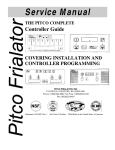
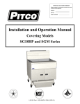
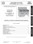
English IMPORTANT INFORMATION FOR FUTURE REFERENCE Record the following information from the appliance ID plate and retain this manual for the life of the equipment: Model #: __________________________ Serial #: __________________________ Date Purchased: ___________________ Operations Manual Covering Pitco # B2005301 SSTC Primary Control for GAS appliances B2005302 SSTC Backup Control for GAS appliances B2005303 SSTC Primary Control for Electric appliances B2005304 SSTC Backup Control for Electric appliances B2005305 SSTC Backup Control for SE147 Electric appliances B2005401 SSTC Primary Control for Flat Bottom GAS appliances Solid State Temperature Control PRIMARY BACKUP FLAT BOTTOM This control was developed by Pitco to replace bulb and capillary thermostats in fryer applications. It utilizes the latest in microprocessor technology and allows a host of features not practical with a simple capillary t-stat. Features include a selectable start up melt cycle, drain valve interlock, faulty probe detection, and a boil out mode. This manual details the operation and adjustment of the Solid State Temperature Control. L20-314 Rev 0 (9/7/07) Solid State Temperature Control (SSTC) 1 Switch and Indicator Locations and Function: PRIMARY On / Off switch: Turns the control on or off. The power indicator will be illuminated when the switch is in the on position. Primary / Backup select switch: In appliances with primary AND a backup control, this switch selects the control that will manage temperature in the appliance. When the switch is in the single dot position, power is diverted to the primary control, typically an I12 cooking computer. When the switch is moved to the two dot position, power is diverted to the Backup control. Melt / No Melt select switch: BACKUP In the melt cycle position, melt cycle will be executed when the appliance first starts up. This melt cycle will end automatically when the temperature conditions are correct to allow full heat. Operators may bypass a running melt cycle by moving the switch to the full heat position. Temperature Set Knob: The position of the pointer sets the cooking temperature of the control. Scales are shown in Fahrenheit and Celsius scales. Power Indicator: This green indicator shows the control is turned on. Heat Demand Indicator: This LED indicator shows when the control is demanding heat. Heat Feed Back/Fault Indicator: This indicator shows when the appliance is heating in response to a heat demand. Under normal conditions, this light will follow the head demand indicator. This indicator is also used to flash conditions for probe faults, drain valve open conditions, or, boil out operations. L20-314 Rev 0 (9/7/07) Page 2 FLAT BOTTOM Solid State Temperature Control (SSTC) 2 2.1 Operation: Turn the appliance ON: Place the melt switch in the desired position, typically Melt . No melt may also be selected only if vat is filled with liquid cooking oil. Turn the control ON by pressing the rocker switch to the “1” position. The green power indicator will illuminate. 2.2 To turn the appliance OFF: Turn the control OFF by pressing the rocker switch to the “O” position. The green power indicator will go out. 2.3 To Set the Cooking Temperature: Adjust the temperature set knob to the desired cooking temperature. 2.4 To Perform a Boil Out operation: Normal maintenance of a fryer requires regular tank cleaning. This process involves draining the vat of oil and filling with water. Cleaning solution is added, and the control is set to boil by the following method: Start with control in the OFF condition. Toggle the on/off switch in the following sequence- ON – OFF – ON – OFF – then ON. This sequence must be performed within 3 seconds. The power and heat demand indicators will turn on. The heat feed back indicator flash continuously to confirm boil mode. HFB indicator flashes every ½ second when in Boil Out mode. To exit boil mode, turn the control Off. 2.5 Drain Valve Interlock: This control monitors the closed condition of the drain valve. If the valve is detected open, the control assumes the vat has been drained and heating control is suspended. The heat feed back indicator will flash 7 times, pause, and repeat. To reset the drain interlock: Close the drain valve. Turn the control OFF. Refill the vat with oil. Turn the control ON. HFB indicator flashes 7 times, pauses, then repeats, until the drain valve is closed. Page 3 L20-314 (9/7/07) Solid State Temperature Control (SSTC) 3 3.1 Fault Detection High Limit Trip or “Heat Failure”: This control monitors the appliance response to heat demand signals. Under normal conditions the heat feed back indicator follows the heat demand indicator. When the appliance fails to respond, the heat feed back indicator will remain off. Typical causes are: High Limit device is tripped and needs to be reset. On gas appliances, a substandard pilot flame, or ignition module problem may be indicated. For electric appliances, an open line fuse may be indicated. Normal operation when HFB indicator follows Heat Demand. Heat Demand without Heat Feed Back is a Fault indication. 3.2 Open or Shorted Probe: This control continually monitors the condition of the thermal sensing probe. If this probe is detected out of range (open or shorted), heat control activities are suspended. The heat feed back indicator will flash 3 times, pause, and repeat. This condition requires repair of the probe, or related wiring. HFB indicator flashes 3 times, pauses, then repeats. 4 Field Calibration If field calibration is deemed necessary, follow these steps: Allow appliance to heat to set point, and allow 30 minutes to stabilize. Measure the vat center oil temperature. Compare this with the knob pointer scale. To reposition the knob, pry off the cap of the knob with a sharp knife blade. Without turning the shaft, loosen the 5/16-compression nut. Pull the knob off. Re-install the knob with the pointer at the temperature indicated on the test thermometer. Tighten the 5/16-compression nut, and install cap. L20-314 (9/7/07) Page 4