1
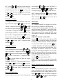
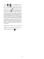
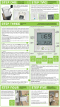
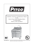
ELECTRIC FRYER with FILTER
PITCO MODEL ME14S-C/MFD
This equipment chapter is to be inserted in the
Fryer section of the Equipment Manual.
MANUFACTURED
EXCLUSIVELY FOR
McDONALD'S®
BY
PITCO FRIALATOR, INC.
P.O.BOX 501
CONCORD, NH 03302-0501
PHONE: 1(603)225-6684
TOLL FREE: 1(800)258-3708
INSTALLATION & OPERATORS MANUAL
TABLE OF CONTENTS
Warranty Statement .......................................................................................................... 1
Installation Instructions ...................................................................................................... 2
Ventilation .......................................................................................................................... 2
Clearances ........................................................................................................................ 2
Once Fryers are in Place ................................................................................................... 2
Equipment Set-Up & Shut Down Procedures .................................................................... 3
Filling the Fryer with Oil ..................................................................................................... 3
Set-Up ............................................................................................................................... 3
Shut Down ......................................................................................................................... 3
The Pitco Frialator Cooking Computer .............................................................................. 4
Operating Instructions ....................................................................................................... 5
Cooking Product ................................................................................................................ 5
Programming the Computer .............................................................................................. 6
Filtering Instructions .......................................................................................................... 11
Troubleshooting Guide ...................................................................................................... 13
Electric Schematic ............................................................................................................. 14
This manual is for the exclusive use of licensees and employees of McDonald's Systems, Inc.
© 1996 McDonald's Corporation
All Rights Reserved
Pitco Frialator Literature # L20-137 Rev 0
Printed 22 May 1996
Manufactured in
The United States of America
WARRANTY STATEMENT
FOR YOUR SAFETY:
DO NOT STORE OR USE GASOLINE OR
OTHER FLAMMABLE VAPORS AND LIQUIDS IN THE VICINITY OF THIS OR ANY
OTHER APPLIANCE.
Pitco Frialator, Inc. makes the following limited warranties to the original purchaser only for this equipment and replacement parts:
1.
WARRANTY PROVISIONS - FRYERS
A. Pitco Frialator, Inc. warrants all parts, with
the exception of the frypot, elements and
computer for 1 year after the date of installation of the fryer.
B. If any parts become defective during the first
year after the installation date, Pitco Frialator will also pay for the labor, freight and
travel costs involved in replacing said part.
WARNING:
IMPROPER INSTALLATION, ADJUSTMENT, ALTERATION, SERVICE OR MAINTENANCE CAN CAUSE PROPERTY DAMAGE, INJURY OR DEATH. READ THE
INSTALLATION, OPERATING AND MAINTENANCE MANUALS THOROUGHLY
BEFORE INSTALLING OR SERVICING
THIS EQUIPMENT.
2.
WARRANTY PROVISIONS - FRYPOTS
A. If a frypot develops a leak due to a defect in
material or workmanship within the first 10
years after installation, Pitco Frialator, Inc.
will either weld or replace, at its discretion,
the frypot.
B. The customer will be responsible for all
freight, labor and travel charges for this repair, except within the period stated in section 1-B.
WARNING:
This machine is intended to be hard
wired when installed in its final location.
3.
WARRANTY PROVISIONS - COMPUTER
A. Pitco Frialator, Inc. will warrant the Intellifry Computer from defects in material or
workmanship for a period of two years.
B. If the computer is found to be defective during the first 2 years after the installation date,
Pitco Frialator Inc. will also pay for the labor, freight and travel costs involved in replacing said part.
4.
WARRANTY PROVISIONS - ELEMENTS
A. Pitco Frialator, Inc. will warrant the Electric
Elements from defects in material or workmanship for a period of 3 years.
B. The customer will be responsible for all
freight, labor and travel charges for this repair, except within the period stated in section 1-B.
Retain this manual for future reference
1
INSTALLATION INSTRUCTIONS
Clearances:
CAUTION:
This equipment is manufactured for the use on a
particular voltage and phase which is specified on
the rating plate located on the inside of the door.
Minimum clearance of 6" (15cm) must be maintained
from combustible construction on each side and the
rear of the equipment. This equipment may be installed on combustible floors.
When your fryers arrive, look them over carefully
noting any damage on the freight bill. If concealed
damage is found after you have accepted the equipment, report it to the carrier immediately as all claims
must be filled within 15 days of the receipt of the
shipment. Also, be sure to keep all packing materials as these will be necessary to make any claim.
Maintain a minimum of 24"(61cm) clearance in front
of the fryer to provide for proper operation, maintenance and servicing.
Wiring diagram(s) are located in the back of the service manual and inside the fryers.
The control (interlock) voltage for this equipment
Follow these installation instructions carefully. A must be 120VAC (US & Canada). For other counproper installation is important for the operation of tries please check the rating plate.
the fryers.
Regular cleaning of this equipment, as well as the
All installations must conform to all local and state hood, is an important part of proper maintenance.
codes and well as the United States National Elec- Refer to Maintenance Requirement Cards for proper
trical Code (ANSI/N.F.P.A. No. 70-1987). In procedure and frequency.
Canada, installations must be made in accordance to
Once the fryers are in place:
Canadian Electrical Code Part I, CSA-C22.1.
Leveling the fryers will help ensure proper operation. To level the fryers loosen the two set screws on
the caster stem. Rotate the collar of the caster to raise
or lower the height of the unit. Tighten set screws to
lock the adjustment. Casters should be adjusted so
that the fryers are level and at the correct height unThe duct system, the hood system and the fryers must der the hood system.
be cleaned on a regular basis and must be kept clear
of any grease build up. See the appropriate Mainte- Clean the fry tanks using the Boil Out procedure on
Maintenance Card 14A.
nance Requirements Cards.
A wiring diagram is located in the back of this manual
Ventilation:
and inside the fryers.
A proper ventilation system is also an important part
of the installation. For information on the construcEQUIPMENT SET UP AND SHUT DOWN
tion and installation of ventilating hoods, please see
“Standard for the Installation of Equipment for the
Removal of Smoke and Grease Laden Vapors from
Commercial Cooking Equipment”, N.F.P.A. No. 961987. Copies can be obtained by writing to the National Fire Protection Association, Battery March
Park, Quincy, MA 02269
Do not block the area around the casters and under
the fryers. Contact the Autorized Pitco Frialator representative for any service related problems. Routine maintenance may be performed by qualified
personnel.
2
PROCEDURES
The computer display will light and the heating elements will begin to heat and will be controlled by
NOTE: Should you experience a power failure, your the computer/controller.
fryers will shut off automatically. Once the power NOTE: From a cold start the fryer will automatihas been restored, press the
key to turn the fryer cally begin a melt cycle. This is a condition where
the computer will heat the shortening in small conback ON. If the machine is being filtered, close the
trolled bursts of heat. Once the predetermined temRED return valve so that the filter does not run if the
perature has been reached, the unit will exit the melt
machine is left un attended. Do not attempt to restart
cycle and go to normal operation. The melt cycle
the fryers until the power is restored.
cannot be overridden.
Filling the fryer with oil:
Make sure that the shortening is at the proper level
after cooking temperature has been reached. It may
It is very important to make sure the oil level is corbe necessary to add shortening to maintain the proper
rect before attempting to heat shortening in your Pitco
level.
fryer.
NOTE: When adding solid shortening to an empty
Liquid shortening can be poured directly into the fry
fry tank, first remove the baskets and support racks
tank until the correct level has been reached. This is
and fill the bottom of the tank with shortening, conindicated by a line on the right hand side of the intinue to pack the remaining shortening into the tank.
side of the tank.
Place the basket support rack on top of the shortening before turning the unit ON.
NOTE: The “COLD” level is considered to be the
For liquid shortening fill to the level lines indicated
“MINIMUM” oil level and the “HOT” level is conon the side of the tank.
sidered to be the “MAXIMUM” oil level.
Shut Down:
For solid shortening, the shortening must be cut into
small blocks about 1" (2.54 Cm) in size. These small
key to turn the fryer OFF.
blocks must be placed under and around the heating Press the corresponding
elements.
The Computer display will go blank and all heating
functions will cease.
The fryer can now be turned ON.
NOTE: When the fryer is not being used, place the
Set-Up:
cover over the fry tank.
NOTE: Please read the Operating instructions thoroughly before attempting to operate this equipment.
Make sure the power cords are plugged into the correct receptacles and the proper building circuit breakers are turned ON.
Press the
key on either side of the full vat com-
puter, or the right
key for the right side and the
left
key for the left side of a split vat computer
to turn the unit ON.
3
THE PITCO FRIALATOR COOKING COMPUTER
ITEM
DESCRIPTION
FUNCTION
A1
A2
A3
A4
1L Timer "In Use" Indicator light
2L Timer "In Use" Indicator light
1R Timer "In Use" Indicator light
2R Timer "In Use" Indicator light
Light will illuminate when a product key is
pressed
B1
B2
B3
B4
1L Program START key
2L Program START key
1R Program START key
2R Program START key
These keys are used to start a product cook cycle
C1
C2
Left Split Vat ON/OFF key
Right Split Vat ON/OFF key
Power ON and OFF keys
D
Program key
For programming use
E
Heating Signal Indicator lights (LEDs
Lights will illuminate when the computer calls
for a heat cycle
F
Temperature key
Used for checking ACTUAL and SET temp.
G
Program Time key
For programming use
H1
H2
Left Display Window
Right Display Window
Illuminated at all times when the machine is ON
I1
I2
Left Selection Arrow
Right selection Arrow
For programming use
4
OPERATING INSTRUCTIONS
Cooking Product:
NOTE: Refer to page 4 for a complete pictorial view Fill the baskets with product, drop the product and
of the Computer/Controller.
touch one of the Left Product keys,
or Right
Product keys,
NOTE: The hood will also be turned ON if any of
the fryers under it is turned ON.
The display will show the cook time in minutes and
seconds (example: 3 00) this time displayed will
count downward toward 0 00. When the pre-programmed Shake time (French Fries only) has elapsed
the alarm will sound and the display will show
“SHAKE”. This indicates that the basket should be
shaken. This alarm is canceled automatically if programmed, or by pressing the product key which has
the illuminated LED.
Turn the Computer/Controller ON by pressing the
key (On Full Vat either
on split vats the Left
to start the cooking timers.
key can be pressed;
operates the Left side and
the Right
operates the Right side.) The Computer/Controller will display the menu item if it is
within temperature range and will alternately flash
the menu item and “WAIT” if it is not.
and
In a Full Vat Fryer, the
To change menu item press the left
keys should be
key or right
used to time the left basket.
and
keys should
key to move through the menu items available. be used to time the right basket. Either key on each
Continue to press the key until the menu item you side work in parallel with the other on that side and
want to cook is shown in the display. On split vat will control the timing for that side. Example: Eifryers, first press
side or the
then the
key to choose left ther
key for right side, then scroll as above.
or
ket. Either
right basket
If the shortening temperature is below 180°F (82°C)
the unit will automatically begin its melt cycle. The
heat demand LED(s) will be lit and the heat cycle
will go ON and OFF automatically to prevent damaging the shortening. The computer will leave the
Melt Cycle automatically and enter Cooking mode
where the programmed cooking temperature will be
maintained.
controls the timing for the left basor
controls the timing for the
In a Split Vat Fryer, if more than one product is being cooked at the same time the LEDs will flash at
different rates. Each key
(Left Side) or
(Right Side) are independent of each other. The
LED which is flashing on that side indicates the cook
cycle which will be completed first. If only one key
is pressed then that LED remains steady. Example:
Normal Melt Cycle time from a cold start is less than
is pressed first and is timing down,
is then
60 Minutes. Times may vary somewhat due to the
flashes while the LED
temperature of the cold shortening and the power pressed. The LED above
being supplied.
above
is steady.
In the Cooking mode, the heat demand LED(s) will
remain ON constantly until the Programmed cooking temperature is reached at which time it will cycle
ON and OFF with the Elements to maintain that temperature.
NOTE: When an alarm sounds all other LED's will
be extinguished and the operator will need to perform the required duty being displayed and cancel
the alarm indicated by the flashing LED. When the
alarm has been canceled the other times will be displayed in progress. No new cook cycles can be
started until the alarm is cancelled.
5
After the cooking time has counted down completely,
the alarm will sound and “PULL” will be displayed
as well as the LED over the product key that needs
attention will flash. If no other products are being
cooked in that vat, “QUAL” and a time counting
down will be displayed. This is Quality time which
indicates how long the last cooked product can be
held in good condition. When the quality time reaches
the programmed cooking time of the product “QA”
will flash in the display.
NOTE: The quality timer is reset if another product
cook cycle is begun on either side for Full Vat or on
the same side for a Split Vat.
by the
key, then press the
key again fol-
lowed by the
key. On right split vat machines
only, use the following sequence of keys to enter the
programming mode the
and
keys.
Choosing Menu Items:
The left display will show the menu item the right
display will indicate “SHOW YES” or “SHOW NO”.
By pressing the
and/or
keys the menu items
can be scrolled and selected. In the right display
“SHOW YES” or “SHOW NO” will indicate which
menu item will be available in cooking mode.
Example: To display only French Fries and Hash
Displaying Actual and Set Vat Temperatures:
Browns on a full vat, press the
and
keys, the last displayed item will show in the left
display “HASH BRN”, right display indicates
“SHOW YES”. This means that this menu item will
once to display the
Press the Temperature key
actual vat temperature, “ACT XXX°F” will be displayed; press it twice to display the set temperature
“SET XXX°F” will be displayed. Press and hold the
key
key to display actual vat temperature as long be available in the cooking mode. Press the
and “PIES” shows in the left display the right disas the key is held or until alarm occurs.
play shows “SHOW YES”. To change the status press
Low Temperature Indication:
. The right display changes to “SHOW NO” indicating that this menu item will not be available in
If the actual vat temperature should fall 15°F (8°C)
below the set temperature the display will alternately
flash “WAIT” and the menu item. Also a very short
alarm (chirp) will sound until the vat temperature
comes within 15°F (8°C) of the set temperature.
the cooking mode. Press the
key to scroll to the
next menu item, “FR FRIES”. The display will indicate “SHOW YES”. Since French fries are to be
available in the cooking mode no action is needed
for this menu item. Press the
key and continue
to change the status of all menu items to “SHOW
NO” except “FR FRIES” and “HASH BRN”. Press
Probe Failure Indication:
Should the probe fail, the display will flash “PROBE”
alternating with “FAILURE” and the alarm will
sound. To cancel this alarm, the computer (or the
one side indicated in the case of a split vat) must be
turned OFF.
the
key to exit program mode and review the
menu items available in cooking mode by pressing
the
and/or
keys. The only menu items that
should show are “FR FRIES” “HASH BRN” and a
non menu item “OPTIONS”.
PROGRAMMING THE COMPUTER
Programming Vat Temperature(s):
NOTE: The computer must be turned ON and display a menu item before the programming mode can Each menu item can be programmed for a cooking
be entered.
temperature. To program a cooking temperature, first
To enter the programming mode on full vat or left scroll to the menu item to be programmed, enter the
side split vat machines, press the
key followed
programming mode by pressing the
6
and
keys for full vat or left side split vat; press the keys for full vat or left side split vat; and the
and
for right side split vat. Press
and
keys for right side split vat. Then press
the
key. The left display will show the previ- the
key twice. In the left display A time in Minously programmed set point Example: “SET 360°F”. utes and Seconds will appear in the left display; in
To change press the
key for hundreds. The hun- the right display the duty name will appear Example:
Left “00 30” Right “SHK TIME”. To change this
dreds digit will flash. Press the
key to lower the
key for minutes, the
key for
time press the
temperature, and the
to raise. To change the
tens of seconds, the
key for ones of seconds.
key. The tens digit will flash.
tens digit press the
Press the
key to save this time. To change to
Press the
key to lower the temperature, and the another duty time within the same menu item press
to raise. To change the ones digit press the
key. The ones digit will flash. Press the
lower the temperature, and the
the
key to
or
keys for “PULL” or “QUAL”. Press
the
key and proceed as above. Press the
key
twice to be able to change menu items and press the
to raise. Press
or
the
key to save the changes and exit the programming mode.
keys to change. Proceed as above.
NOTE: To return all setting to the factory pro-
NOTE: A maximum of 380°F (193°C) and minimum of 200°F (93°C) can be programmed.
grammed specifications press the
and
keys the left display will show “RESTORE”, the right
display will show “FACT NO”. To reset to factory
Manual and Automatic Cancel of Alarms:
specs press the
key and the right display will
The shake alarm can be set to Auto (self-cancel after read "FACT YES"; press the
7 seconds of sounding) or Manual cancel which re- choice.
quires the product key to be pressed to cancel the
audible alarm. To change the status from Manual High Limit Testing:
cancel to Auto cancel, first select the menu item then
enter the programming mode by pressing the
and
Before testing the High Limits use the
or
keys until “OPTIONS” is shown in the left display
for full vat and left side of split vat or right display
keys for full vat or left side split
vat; and the
and
key to save this
keys for right side
for right side of split vat. Press the
and
split vat. Then press the
key. The left display
keys. Use the
or
keys until the left diswill show the alarm Example: “SHAKE A” (A for
keys again
auto), the right display will show “AUTO CNC”. To play shows “HI LIMIT” Press the
change, press the
key. The displays will change and the actual vat temperatures will be shown Example: “ACT 360°F”.
to “SHAKE M” and “MAN CNC”. Each menu item
can be individually programmed in this manner.
First High Limit (Internal)
Programming Times:
Press and hold the
key. The heat demand relay
First select the menu item then enter the program- will engage and the heat demand LED(s) will be lit.
ming mode by pressing the
and
(For right side split vat the
7
key must be pressed
and held.) The first high limit is internal to the computer and should trip between the temperatures of
400°F (204°C) and 420°F (215°C). This trip will be
indicated in 2 ways: First the heat demand LED(s)
will go out; second the display will alternate between
“HI 1” and “XXX°F” or “XXX°C”, indicating the
trip temperature. This display will continue until the
vat temperature drops below 400°F (204°C).
If the first high limit fails to trip within the specified
range 400°F (204°C) and 420°F (215°C) the display
will alternate between “HI 1” and “BAD” until either the second high limit test is started (see below)
or the test is ended. Proceed to the Second High Limit
test or to end the test press the
the fryer OFF and back ON.
and
keys and scroll again using the
or
key until “DEGREES” is displayed. Press the
key again and “DEGREE F” OR “DEGREE C”
will be displayed. Press the
the
key to change. Press
key again to save this choice. To exit to the
cooking mode scroll using the
or
“EXIT” is displayed, then press the
key until
key.
Boil Mode:
key twice to turn
In the cooking mode scroll using the
or
key
until “OPTIONS” is displayed. Press the
Second High Limit (Mechanical)
and
keys and scroll again using the
or
key until “BOIL” is displayed. Press the
key
Proceed with the first high limit test (see above).
Once the first high limit has been tripped, press and to start the boil timer. “BOIL OUT” and then “BOIL
hold the # 2 Left Product Key
or # 2 Right Prod- 60 00” will be displayed. The “60 00” is a sixty
minute timer which will count down during the boil
uct Key
. The heat demand relay will activate mode.
and the heat demand LED(s) will light up. The vat
temperature is displayed continuously. The second NOTE: The boil mode cannot be accessed if the vat
high limit should trip between 425°F (218°C) and temperature is above 212°F (100°C). At the end of
450°F (232°C). When the trip occurs the display will the boil time cycle the audible alarm will sound one
alternate between “HI 2” and “XXX°F” or “XXX°C” short beep and the display will show “BOIL DONE”
indicating the trip temperature. If the vat tempera- and the LED will flash. Press the key under the flashture reach 460°F (237°C) without tripping the sec- ing LED to cancel the boil mode. The display will
ond high limit the computer will automatically shut show “TURN OFF”.
OFF the heat. The Left Product key
or Right
NOTE: The unit must be turned OFF using the
Product Key
will no longer control the heat dekey to exit boil out mode.
mand. After 30 seconds the computer will sound an
alarm and the display will alternate between “HI 2”
Alarm Volume:
and “BAD”. Should this occur the alarm can only be
shut off by turning the computer OFF using the
key(s).
To change the volume of the audible alarms (except
Wait Alarm. See below.), in the cooking mode scroll
using the
Changing between Degrees Fahrenheit and
Celsius:
or
played. Press the
again using the
In the cooking mode, scroll using the
or
key until “OPTIONS” is dis-
key
and
or
keys and scroll
key until “VOLUME A”
is displayed. Press the
key again and the display
will show “VOL OFF”, “VOL LOW” OR “VOL
until “OPTIONS” is displayed. Press the
8
or
scroll keys to move between scroll using the
or
key until “OPTIONS” is
HI”. Use the
these choices. The alarm will sound as an example displayed. Press the
and
keys and
of each selection. Press the
key to save any
scroll again using the
or
key until “RECOVchanges made. To exit to cooking mode scroll using
ERY” is displayed. Press the
key again and the
the
or
keys until “EXIT” is displayed, then
display will show the latest recovery time “NEW
press the
key.
XXX” . Press the
or
key to review the “OLD
XXX” and “STD XXX” times.
Wait Alarm Volume:
Filter Timer:
To change the volume of the wait alarm, in the cooking mode, scroll using the
or
key until “OP-
The computer/controller is equipped with a filter
TIONS” is displayed. Press the
and
timer to time the cleansing of the shortening.
To initiate the filter timer, open the drain valve, the
keys and scroll again using the
or
key until
display will show “DRAINING”. Once all the short“VOLUME W” is displayed. Press the
key again ening has been drained down into the filter, turn the
and the display will show “VOL LOW” OR “VOL filter return pump ON by opening the RED return
valve handle as shown in the filtering instructions
HI”. Use the # 2 Right Product Key
to move
on page 10.
key to save KEEP THE DRAIN VALVE OPEN.
between these choices. Press the
changes. To exit to the cooking mode, scroll using Press the
key. A five minute timer will start (FTR
the
or
press the
key until “EXIT” is displayed, then
5 00) at the end of which the alarm will sound and
the display will flash “FILTER” “DONE” alternately.
key.
To cancel the audible alarm press the
key.
“CLOSE” “DRAIN” will flash alternately because
the drain valve is still open. Closed the drain valve.
The display will inidcate “TURN OFF”. Continue
to pump the shortening until bubbles are seen in the
tank. This indicates that the filter return lines have
been emptied and the pump can be turned OFF by
closing the RED return valve handle.
Language Selection:
In the cooking mode scroll using the
or
key
until “OPTIONS” is displayed. Press the
and
keys and scroll again using the
or
key until “LANGUAGE” is displayed. Press
Press the
key to turn the fryer OFF.
the
key and the display will show the current NOTE: The fryer will not return to the cooking mode
language selection
until the fryer has been turned OFF and back ON
Example: “ENGLISH”. Change languages by press- again.
ing the
or
key. Press the
key to save
Electric Element Burn Off (Electric Fryers
your selection. To exit to cooking mode scroll using
ONLY):
the
or
key until “EXIT” is displayed, then
The computer/controller provides a means to perpress the
key.
form a controlled burn off of the elements. To enter
the Burn Off mode, in the cooking mode scroll usRecovery Time Review:
ing the
or
key until “OPTIONS” is displayed.
To review the recovery times, in the cooking mode
Press the
and
keys and scroll again
9
using the
or
key until “BURN OFF” is dis-
played. Press the
key and the Left Display will
show “CONFIRM” in the Right Display will show
“ELEC NO “. Press the
key to change to “ELEC
YES” then press the
key to begin the three minute
heating cycle. The display will show “BURN 3 00”.
The heat demand LEDs will remain on indicating
the elements are heating. If the 2nd High Limit Trips,
ending the elements burn cycle, the display will indicate “IGNITION” “FAILURE”. If the timer ends
the burn cycle the alarm will sound, the heat demand
LEDs will go out and the display will show “BURN”
DONE” alternately. Press the product key below the
flashing LED to cancel the alarm. The display will
then show “TURN OFF” indicating that the fryer
must be turned OFF and back ON to return to the
cooking mode.
NOTE: Either side of a split vat can be Burned off.
NOTE: The Burn Off Mode can be ended at anytime by pressing either of the
keys.
10
FILTERING INSTRUCTIONS
·
Filter shortening in accordance to the Operations and
·
Training Manual.
WARNING:
Shortening, when it is at cooking temperatures, is
very HOT and DANGEROUS! Use extreme caution when handling! Use the proper protective gear
such as insulated gloves, aprons, face shield and
sleeves when handling hot shortening. When discarding used shortening, drain the fryer into the appropriate receptacle, move the receptacle to the
grease barrel and pump the old shortening into the
grease barrel.
·
·
·
WARNING:
Do not attempt to drain more than one vat at a time.
This will overfill the filter pan and could cause severe injury and equipment damage.
Place filter Paper or Pad over screen making sure
that there is an equal amount of excess paper on
each side.
Place the Retaining Frame on the paper or pad
making sure that all edges are being pressed down
evenly.
Add powder (if used) per instructions on packet.
Replace the cover by pushing the rear edge over
the back of the pan, lay the cover onto the pan
and pull forward, the cover should now locate
itself on the pan edges.
Slide filter drawer back under fryer making sure
that the oil return pipe locates into its mating
connection. Both sides should now be latched
correctly so that the filter pan remains in place
under the fryer.
CAUTION:
Be careful when using the clean out rod. Damage
to the drain valve may result.
WARNING:
Hot shortening can cause severe injury. Take care
when filtering or disposing of hot shortening. Protective gear such as gloves, apron, face shield and
sleeves should be worn.
Preparing the filter for use:
· Disengage filter drawer latches by grasping the
handle across the front of the pan. Pull up on the
handle and the pan can be pulled out.
· Slide drawer forward until it stops.
· Remove the pan cover by grasping the handle on Operating Instructions of Filter
the front right hand side. Push the cover backwards about 1 inch and disengage the rear of the
CAUTION:
cover from the pan. (You may have to shake the Do not attempt to filter unless shortening is at cookcover to do this.)
ing temperature.
· Grasp the Left and Right handles of the Paper
Retaining Frame and lift upward to remove it.
· Open the drain valve. Unlatch the locking pin by pushing the small GREEN lever away from valve body and
· Remove the filter paper or pad by folding the
simultaneously pulling the GREEN drain valve handle
edges inward so that the debris is collected.
down until it stops. The Display will show “DRAIN· Lift the Paper Support Screen out of the pan.
ING”.
· The Pan, Paper Support Screen and Paper Re· Allow the shortening to drain to the level of the
taining Frame can now be cleaned.
heating elements.
·
Close the drain valve. Push the GREEN drain valve
NOTE: Be sure that the filter pan is free of any dehandle upward until the locking pin latches. (It is not necessary to push the small GREEN lever in order to make it
latch.) The Display will show “TURN OFF”.
bris which could cause the paper and hold down ring
not to seat properly.
·
Place the Paper Support Screen in the bottom of
the pan making sure that the screen is located on
the two retaining pins in the bottom of the pan.
·
Clean the fry vat.
Dip the cleaning tool in oil and wet down the vat walls.
Sprinkle the walls and elements with McDonald’s Fryer
Cleanser. Scrub all surfaces with the fryer cleaning tool.
11
Make sure all cleaner residue is removed from inside the
fry vat.
·
Open the GREEN Drain Valve.
·
Press the
key on computer.
Display will show “FTR MM SS”.
Open the RED Return Valve. Pull downward on the
·
Red Lever until you hear the pump operate.
·
·
·
·
·
Brush the residue in the bottom of tank down
into the drain.
The filter timer will time out and the Display will
show “FILTER”/”DONE” and an audible alarm
will sound.
Press the
key, the Display will show
“CLOSE”/“DRAIN”.
Close the GREEN Drain Valve. The Display will
show “TURN OFF” and the Fry Vat will refill.
Allow all of the shortening to return to the tank. Bubbles
will be produced in the vat when all the shortening has
been returned. This means that the return lines have been
cleared.
Close the RED Return Valve. Push upward on the
Red Return Valve Handle. This will turn the pump
off.
·
·
Press the
key and the Display will show
“OFF”.
Allow the Drain and Return lines to drain for at
least 5 minutes before removing filter pan to reduce dripping.
Your machine is now ready to cook with.
12
TROUBLESHOOTING
PROBLEM
PROBABLE CAUSE
CORRECTIVE ACTION
Computer does not come on
nothing shows in either display
A. Main circuit breaker is
turned off
B. Fryer fuse is blown
A. Locate the correct building circuit breaker
and turn OFF and back ON again.
B. Call an Authorized Service Technician
Computer heat light comes on
but elements do not heat
A. If the oil is hot the Hi - Limit
may be tripped
A. Allow the oil to cool, reset the Hi Limit and turn
the computer OFF and back ON again.
Computer display shows
"OFF" and cannot be turned
"ON".
A. Bad computer
A. Locate the correct building circuit breaker and
turn OFF and back ON again. If this does not
reset the computer call an Authorized Service
Technician.
Elements will not lower into
the fry vat
A. Latch stuck
A. Lift elements slightly and pull the latch forward,
the elements should now drop with a little
downward pressure.
RED return valve is open no
pump sound can be heard
A. RED return valve not fully
open
B. Filter circuit breaker may be
tripped
C. Filter motor Thermal Overload may be tripped
D. Sensor switch may be loose
A. Pull slightly on the RED return valve handle
Drain valve is closed and
the computer has been
reset but still shows
"DRAINING" or
"TURN OFF"
A. GREEN drain valve is not
fully closed
B. Sensor switch may be loose
Drain valve is open, the oil is
draining slowly or not at all.
A. GREEN drain valve is not
fully open
B. Drain is plugged with debris
13
B. Locate the filter circuit breaker behind the door
of the left hand fryer and reset it.
C. Push RED reset button located on end of filter
motor, behind the door of left hand fryer.
D. If the mounting screws are loose try to tighten
them, if this is not possible call an Authorized
Service Agency.
A. Apply a little more pressure to close the valve
B.
If the mounting screws are loose try to tighten
them, if this is not possible call an Authorized
Service Agency.
A. Apply a little more pressure to open the valve
B. Use the clean out rod from inside the fry vat to
clear the drain valve. If this does not clear the
blockage, CLOSE the GREEN drain valve and
follow the instructions for clearing the main drain
line.
CAUTION:
Some HOT oil may come out when the cap is
removed.
Remove the four thumb screws from the end cap
(do NOT lose these.) Use the clean out rod to
clear the main drain tube. Install the end cap
along with its gasket and four screws. Do not
overtighten these screws.
To obtain copies of any McDonalds Operating or Service Manuals please
contact Pitco Frialator at the address below, please reference the
literature number for the publication you require:
L20-137 - McDonalds Electric Operating Manual
L20-138 - McDonalds Gas Operating Manual
L20-139 - McDonalds Electric Service Manual
L20-140 - McDonalds Gas Service Manual
In the event of problems with or questions about
you order, please contact the Pitco Frialator factory, from 8:00 a.m. - 5:00 p.m., Eastern Standard
Time, Monday through Friday, toll-free at:
(800)258-3708 US and Canada only or
(603)225-6684 World Wide
In the event of problems with or questions about
you equipment, please contact the Pitco Frialator
Authorized Service and Parts representative
(ASAP) covering you area, through the National
Service Network at:
(800)298-1862 US only, 24 hours