1
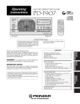
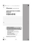
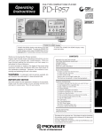
VIDEO SWITCHER
VSW-1
Operating Instructions
Thank you for buying this Pioneer product.
Please read through these operating instructions so you will know how to operate your model properly. After you have finished
reading the instructions, put them away in a safe place for future reference.
In some countries or regions, the shape of the power plug and power outlet may sometimes differ from that shown in the explanatory
drawings. However the method of connecting and operating the unit is the same.
K015 En
WARNING
IMPORTANT
This equipment is not waterproof. To prevent a fire
or shock hazard, do not place any container filed
with liquid near this equipment (such as a vase or
flower pot) or expose it to dripping, splashing, rain
D3-4-2-1-3_A_En
or moisture.
CAUTION
RISK OF ELECTRIC SHOCK
DO NOT OPEN
The lightning flash with arrowhead symbol,
within an equilateral triangle, is intended to
alert the user to the presence of uninsulated
"dangerous voltage" within the product's
enclosure that may be of sufficient
magnitude to constitute a risk of electric
shock to persons.
CAUTION:
TO PREVENT THE RISK OF ELECTRIC
SHOCK, DO NOT REMOVE COVER (OR
BACK). NO USER-SERVICEABLE PARTS
INSIDE. REFER SERVICING TO QUALIFIED
SERVICE PERSONNEL.
The exclamation point within an equilateral
triangle is intended to alert the user to the
presence of important operating and
maintenance (servicing) instructions in the
literature accompanying the appliance.
D3-4-2-1-1_En-A
NOTE: THE NO USER-SERVICEABLE PARTS COMPARTMENT WARNING IS LOCATED ON THE APPLIANCE BOTTOM.
When using this product follow the instructions
written on the underside of the unit, which
D3-4-2-2-4_En
concern rated voltage, etc.
IMPORTANT NOTICE – THE SERIAL NUMBER FOR
THIS EQUIPMENT IS LOCATED IN THE REAR.
PLEASE WRITE THIS SERIAL NUMBER ON YOUR
ENCLOSED WARRANTY CARD AND KEEP IN A
SECURE AREA. THIS IS FOR YOUR SECURITY.
D1-4-2-6-1_En
READ INSTRUCTIONS — All the safety and
operating instructions should be read before the
product is operated.
RETAIN INSTRUCTIONS — The safety and
operating instructions should be retained for
future reference.
HEED WARNINGS — All warnings on the product
and in the operating instructions should be
adhered to.
FOLLOW INSTRUCTIONS — All operating and use
instructions should be followed.
CLEANING — The product should be cleaned only
with a polishing cloth or a soft dry cloth. Never
clean with furniture wax, benzine, insecticides
or other volatile liquids since they may corrode
the cabinet.
ATTACHMENTS — Do not use attachments not
recommended by the product manufacturer as
they may cause hazards.
WATER AND MOISTURE — Do not use this
product near water — for example, near a
bathtub, wash bowl, kitchen sink, or laundry
tub; in a wet basement; or near a swimming
pool; and the like.
ACCESSORIES — Do not place this product on an
unstable cart, stand, tripod, bracket, or table.
The product may fall, causing serious injury to a
child or adult, and serious damage to the
product. Use only with a cart, stand, tripod,
bracket, or table recommended by the
manufacturer, or sold with the product. Any
mounting of the product should follow the
manufacturer’s instructions, and should use a
mounting accessory recommended by the
manufacturer.
CART — A product and cart combination should be
moved with care. Quick stops, excessive force,
and uneven surfaces may cause the product
and cart combination to overturn.
VENTILATION — Slots and openings in the cabinet
are provided for ventilation and to ensure
reliable operation of the product and to protect
it from overheating, and these openings must
not be blocked or covered. The openings should
never be blocked by placing the product on a
bed, sofa, rug, or other similar surface. This
product should not be placed in a built-in
installation such as a bookcase or rack unless
proper ventilation is provided or the
manufacturer’s instructions have been adhered
to.
POWER SOURCES — This product should be
operated only from the type of power source
indicated on the marking label. If you are not
sure of the type of power supply to your home,
consult your product dealer or local power
company.
LOCATION – The appliance should be installed in a
stable location.
NONUSE PERIODS – The power cord of the
appliance should be unplugged from the outlet
when left un-used for a long period of time.
GROUNDING OR POLARIZATION
• If this product is equipped with a polarized
alternating current line plug (a plug having one
blade wider than the other), it will fit into the
outlet only one way. This is a safety feature. If
you are unable to insert the plug fully into the
outlet, try reversing the plug. If the plug should
still fail to fit, contact your electrician to replace
your obsolete outlet. Do not defeat the safety
purpose of the polarized plug.
• If this product is equipped with a three-wire
grounding type plug, a plug having a third
(grounding) pin, it will only fit into a grounding
type power outlet. This is a safety feature. If you
are unable to insert the plug into the outlet,
contact your electrician to replace your obsolete
outlet. Do not defeat the safety purpose of the
grounding type plug.
POWER-CORD PROTECTION — Power-supply
cords should be routed so that they are not likely
to be walked on or pinched by items placed
upon or against them, paying particular
attention to cords at plugs, convenience
receptacles, and the point where they exit from
the product.
OUTDOOR ANTENNA GROUNDING — If an
outside antenna or cable system is connected to
the product, be sure the antenna or cable
system is grounded so as to provide some
protection against voltage surges and built-up
static charges. Article 810 of the National
Electrical Code, ANSI/NFPA 70, provides
information with regard to proper grounding of
the mast and supporting structure, grounding of
the lead-in wire to an antenna discharge unit,
size of grounding conductors, location of
antenna-discharge unit, connection to
grounding electrodes, and requirements for the
grounding electrode. See Figure A.
LIGHTNING — For added protection for this
product during a lightning storm, or when it is
left unattended and unused for long periods of
time, unplug it from the wall outlet and
disconnect the antenna or cable system. This
will prevent damage to the product due to
lightning and power-line surges.
POWER LINES — An outside antenna system
should not be located in the vicinity of overhead
power lines or other electric light or power
circuits, or where it can fall into such power
lines or circuits. When installing an outside
antenna system, extreme care should be taken
to keep from touching such power lines or
circuits as contact with them might be fatal.
OVERLOADING — Do not overload wall outlets,
extension cords, or integral convenience
receptacles as this can result in a risk of fire or
electric shock.
OBJECT AND LIQUID ENTRY — Never push
objects of any kind into this product through
openings as they may touch dangerous voltage
points or short-out parts that could result in a
fire or electric shock. Never spill liquid of any
kind on the product.
SERVICING — Do not attempt to service this
product yourself as opening or removing covers
may expose you to dangerous voltage or other
hazards. Refer all servicing to qualified service
personnel.
DAMAGE REQUIRING SERVICE — Unplug this
product from the wall outlet and refer servicing
to qualified service personnel under the
following conditions:
• When the power-supply cord or plug is
damaged.
• If liquid has been spilled, or objects have fallen
into the product.
• If the product has been exposed to rain or water.
• If the product does not operate normally by
following the operating instructions. Adjust only
those controls that are covered by the operating
instructions as an improper adjustment of other
controls may result in damage and will often
require extensive work by a qualified technician
to restore the product to its normal operation.
• If the product has been dropped or damaged in
any way.
• When the product exhibits a distinct change in
performance — this indicates a need for service.
REPLACEMENT PARTS — When replacement parts
are required, be sure the service technician has
used replacement parts specified by the
manufacturer or have the same characteristics
as the original part. Unauthorized substitutions
may result in fire, electric shock, or other
hazards.
SAFETY CHECK — Upon completion of any service
or repairs to this product, ask the service
technician to perform safety checks to
determine that the product is in proper
operating condition.
WALL OR CEILING MOUNTING — The product
should not be mounted to a wall or ceiling.
HEAT — The product should be situated away from
heat sources such as radiators, heat registers,
stoves, or other products (including amplifiers)
that produce heat.
ANTENNA
LEAD IN
WIRE
GROUND
CLAMP
ANTENNA
DISCHARGE UNIT
(NEC SECTION 810-20)
ELECTRIC
SERVICE
EQUIPMENT
Fig. A
POWER SERVICE GROUNDING
ELECTRODE SYSTEM
(NEC ART 250, PART H)
D1-4-2-2_En
NOTE: This equipment has been tested and found to comply with the limits for a Class B digital device, pursuant to
Part 15 of the FCC Rules. These limits are designed to provide reasonable protection against harmful interference in
a residential installation. This equipment generates, uses, and can radiate radio frequency energy and, if not
installed and used in accordance with the instructions, may cause harmful interference to radio communications.
However, there is no guarantee that interference will not occur in a particular installation. If this equipment does
cause harmful interference to radio or television reception, which can be determined by turning the equipment off
and on, the user is encouraged to try to correct the interference by one or more of the following measures:
2
D8-10-2_En
CAUTION: This product satisfies FCC regulations
when shielded cables and connectors are used to
connect the unit to other equipment. To prevent
electromagnetic interference with electric appliances
such as radios and televisions, use shielded cables
and connectors for connections.
D8-10-3a_En
This Class B digital apparatus complies with
Canadian ICES-003.
Cet appareil numérique de la Classe B est conforme
à la norme NMB-003 du Canada.
D8-10-1-3_EF
CAUTION
– PREVENT ELECTRIC SHOCK DO
NOT USE THIS (POLARIZED) PLUG
WITH AN EXTENSION CORD.
RECEPTACLE OR OTHER OUTLET
UNLESS THE BLADES CAN BE
FULLY INSERTED TO PREVENT
BLADE EXPOSURE.
ATTENTION – POUR PREVENIR LES CHOCS
ELECTRIQUES NE PAS UTILISER
CETTE FICHE POLARISEE AVEC UN
PROLONGATEUR UNE PRISE DE
COURANT OU UNE AUTRE SORTIE
DE COURANT, SAUF SI LES LAMES
PEUVENT ETRE INSEREES A FOND
SANS EN LAISSER AUCUNE PARTIE
A DECOUVVERT.
D2-4-4-1_EF
WARNING: Handling the cord on this product or
cords associated with accessories sold with the
product will expose you to lead, a chemical known to
the State of California and other governmental
entities to cause cancer and birth defects or other
reproductive harm.
Wash hands after handling
D36-P4_En
GROUNDING CONDUCTORS
(NEC SECTION 810-21)
GROUND CLAMPS
NEC — NATIONAL ELECTRICAL CODE
–
–
–
–
Information to User
Alteration or modifications carried out without
appropriate authorization may invalidate the user’s
right to operate the equipment.
Reorient or relocate the receiving antenna.
Increase the separation between the equipment and receiver.
Connect the equipment into an outlet on a circuit different from that to which the receiver is connected.
Consult the dealer or an experienced radio/TV technician for help.
D8-10-1-2_En
POWER-CORD CAUTION
Handle the power cord by the plug. Do not pull out the
plug by tugging the cord and never touch the power
cord when your hands are wet as this could cause a
short circuit or electric shock. Do not place the unit, a
piece of furniture, etc., on the power cord, or pinch the
cord. Never make a knot in the cord or tie it with other
cords. The power cords should be routed such that they
are not likely to be stepped on. A damaged power cord
can cause a fire or give you an electrical shock. Check
the power cord once in a while. When you find it
damaged, ask your nearest PIONEER authorized
service center or your dealer for a replacement. S002_En
Features/Specifications
Features
1. Quick response
Using the latest circuit technology, this unit
suppresses noises and color distortion even
during sudden switchovers.
2. Automatic switching
Can be combined with a Pioneer DJ mixer for
video switching linked to the fader start mode.
3. Full complement of input/output
connectors
Supports component video, S-Video, and
composite video IN/OUT signals.
(Signals are only input and output; no conversion function
is provided.)
Handling Precautions
Installation location
¶ Do not install above an amplifier or other heat-emitting component, or use for long periods near spotlights or other heademitting appliances, since the unit may suffer adverse effects.
¶ Install away from tuners and television sets. When placed
near such components, noise and video distortion may occur;
such effects are particularly subject to occurrence when an
internal antenna is used; in such cases, either use an external
antenna, or turn off this unit’s power.
¶ The screws on the right and left sides of this unit can be used
to mount the unit in a rack installation or stand. For details,
consult your dealer.
Note:
When installing the unit in a rack or stand, always use the screw
holes provided on the right and left sides of the unit.
Specifications
1. General
Power ............................................................... AC 120 V, 60 Hz
Power consumption ............................................................ 8 W
Operating temperature ....................................... +5°C to +35°C
Storage temperature ......................................... –40°C to +60°C
Operating humidity .............. 5-85 % R.H. (without precipitation)
Weight .............................................................................. 1.4 kg
External dimensions ................. 250 (W) x 88 (D) x 87.5 (H) mm
(not including connectors, buttons and other protruding parts)
2. Video input section (input level/impedance)
Component video ................... BNC connectors x 3 (2 systems)
Y ............................................................................ 1 Vp-p / 75 Ω
CB/PB .................................................................................................... 0.7 Vp-p / 75 Ω
CR/PR .................................................................................................... 0.7 Vp-p / 75 Ω
S-Video ................................................ S connector (2 systems)
Y ............................................................................ 1 Vp-p / 75 Ω
C ..................................................................... 0.286 Vp-p / 75 Ω
Composite video ............................ RCA connector (2 systems)
1 Vp-p / 75 Ω
3. Video output section (output level/impedance)
Component video ..................... BNC connectors x 3 (1 system)
Y ............................................................................ 1 Vp-p / 75 Ω
CB/PB .................................................................................................... 0.7 Vp-p / 75 Ω
CR/PR .................................................................................................... 0.7 Vp-p / 75 Ω
S-Video .................................................. S connector (1 system)
Y ............................................................................ 1 Vp-p / 75 Ω
C ..................................................................... 0.286 Vp-p / 75 Ω
Composite video .............................. RCA connector (1 system)
1 Vp-p / 75 Ω
4. Sync signal output section
Sync output .................................... BNC connector (2 systems)
1 Vp-p / 75 Ω
Supported video modulation systems ....................... NTSC/PAL
5. Other connectors
Control input ................................... minijack (3.5 dia) 2 systems
Control output ................................ minijack (3.5 dia) 2 systems
6. Accessories
¶
¶
¶
¶
BNC cables .......................................................................... 2
Control cables ...................................................................... 2
Operating Instructions ......................................................... 1
Warranty .............................................................................. 1
For improvement purposes, specifications and design may be
subject to modification without notice.
Cleaning the Unit
÷ Use a polishing cloth to wipe off dust and dirt.
÷ When the surfaces are very dirty, wipe with a soft cloth dipped
in some neutral cleanser diluted five or six times with water
and wrung out well, then wipe again with a dry cloth. Do not
use furniture wax or cleaners.
÷ Never use thinners, benzene, insecticide sprays or other
chemicals on or near this unit, since these will corrode the
surfaces.
3
Connections
Connections
Connection Panel
1
2
PLAYER B
COMPOSITE
S
3
MIXER
PL CONT
PL B CONT
4
PLAYER A
COMPOSITE
S
5
MIXER
PL CONT
PL A CONT
6
VIDEO OUT
CHROMA SYNC
COMPOSITE
COMPOSITE
S
COMPONENT
S
Y
COMPONENT
CB / PB
CR / PR
SYNC
Y
COMPONENT
CB / PB
1. PLAYER B connectors
Use to connect this unit to player B (DVJ-X1).
COMPOSITE
Composite video input connector (RCA pin jack x 1).
Use video cable (provided with DVJ-X1) to connect to player B’s VIDEO
OUT connector.
S
S-Video input connector (4-pin mini DIN connector x 1).
Use a S-Video cable (sold separately) to connect to the player B’s SVideo VIDEO OUT connector.
COMPONENT
Component video input connectors (BNC connectors x 3).
Use 3 BNC plug coaxial cables (sold separately) to connect to player
B’s component video output connectors (Y, CB/PB, CR/PR).
PL CONT
Player control connector, used to control player, fader start and other
operations (minijack x 1).
Use the control cable (provided with DVJ-X1) to connect to player B’s
CONTROL connector.
SYNC
Video sync signal output connector (BNC connector x 1).
The sync signal is used to synchronize video signals between players
A and B, thus preventing video distortion resulting from mix-matched
signals when switching between images.
Use the BNC plug coaxial cable (furnished with this unit) to connect
to player B’s SYNC IN connector.
2. Player B control input connector (MIXER)
PL B CONT
Intermediary connector for player control signals (for fader start, etc.)
from the DJ mixer (minijack x 1).
Use the control cable (furnished with this unit) to connect to the CONTROL connector of the channel which will control the DJ mixer’s player
B.
3. PLAYER A connectors
Use to connect this unit to player A (DVJ-X1).
COMPOSITE
Composite video input connector (RCA pin jack x 1).
Use a video cable (supplied with DVJ-X1) to connect to player A’s
VIDEO OUT connector.
S
4
CR / PR
SYNC
Y
CB / PB
CR / PR
PL CONT
Player control connector, used to control player, fader start and other
operations (minijack x 1).
Use the control cable (provided with DVJ-X1) to connect to player A’s
CONTROL connector.
SYNC
Video sync signal output connector (BNC connector x 1).
The sync signal is used to synchronize video signals between players
A and B, thus preventing video distortion resulting from mix-matched
signals when switching between images.
Use the BNC plug coaxial cable (furnished with this unit) to connect
to player A’s SYNC IN connector.
4. Player A control input connector (MIXER)
PL A CONT
Intermediary connector for player control signals (for fader start, etc.)
from DJ mixer (minijack x 1).
Use the control cable (furnished with this unit) to connect to the CONTROL connector of the channel that will control the DJ mixer’s player
A.
5. VIDEO OUT connectors
Connect to video monitor.
Note:
In order to produce the various video system outputs, the same input
system signals are necessary (the unit does not perform video signal
conversion).
COMPOSITE
Composite video output connector for player A or player B as selected by this unit (RCA pin jack).
S
S-Video output connector for player A or player B as selected by this
unit (4-pin mini DIN connector).
In order to support very quick switching of video signals, this unit
does not support S2 video signals.
Y, CB/PB, CR/PR
Component video output connectors for player A or player B as selected by this unit (BNC connectors x 3).
6. CHROMA SYNC selector switch
Use to select chroma signal phase comparator. Set this in accordance with the setting of the main monitor connected to the video
output connectors.
S-Video input connector (4-pin mini DIN connector x 1).
Use a S-Video cable (sold separately) to connect to the player A’s SVideo VIDEO OUT connector.
S
COMPONENT
Sets chroma signal phase comparator to composite video signal.
Component video input connectors (BNC connectors x 3).
Use 3 BNC plug coaxial cables (sold separately) to connect to player
A’s component video output connectors (Y, CB/PB, CR/PR).
COMPONENT
Sets chroma signal phase comparator to S-Video.
COMPOSITE
Phase comparison is not performed. Use this position when using
components other than DVJ-X1.
Connections
Basic Connections
This unit is designed to allow switching between component video, S-Video, and composite video signals, but does not support signal
conversion. As a result, the same signals required for output must be input. Further, while three different types of signals can be
connected simultaneously for switching between them, only one of the types must be selected for chroma signal synchronization.
When connecting or changing the installation of components, always turn off power and disconnect power cord’s plug from
their outlets before proceeding.
DJ mixer
Main monitor
主電源
入
切
電源(受像) 入力切換
小 音量 大
選局
電源
S-VIDEO
INPUT
COMPONENT
VIDEO INPUT
VIDEO
INPUT
CR PR
VSW-1
CB PB
Y
PLAYER B
COMPOSITE
MIXER
PL CONT
S
PLAYER A
PL B CONT
COMPOSITE
MIXER
PL CONT
S
PL A CONT
VIDEO OUT
CHROMA SYNC
COMPOSITE
COMPOSITE
S
COMPONENT
S
Y
COMPONENT
CB / PB
CR / PR
SYNC
Y
Y
COMPONENT
CB / PB
CB PB CR PR
CR / PR
SYNC
Y
CB / PB
CR / PR
Y
COMPOSITE
NORMAL
DJ
MODE
COMPOSITE
MODE
DIGITAL
AUDIO OUT
VIDEO OUT
DIGITAL
OUT
OUT
SYNC IN
SYNC IN
L
S
CONTROL
S
PREVIEW OUT
VIDEO
INPUT
Player B
AUDIO OUT
VIDEO OUT
L
S
R
S
CONTROL
R
DVJ-X1
CB PB CR PR
NORMAL
DJ
PREVIEW OUT
VIDEO
INPUT
S-VIDEO
INPUT
Preview monitor
Video cable furnished with DVJ-X1
BNC plug coaxial cable furnished with this unit
Control cable furnished with this unit or with DVJ-X1
Audio cable furnished with DVJ-X1
DVJ-X1
Player A
S-VIDEO
INPUT
Preview monitor
Video cable (sold separately)
S-Video cable (sold separately)
BNC plug coaxial cable (sold separately)
Power cord connection
After all other connections are completed, insert the power cord’s plug into a wall power outlet or the auxiliary power outlet of an
amplifier.
5
Operation
Operation
This unit is a 2-channel video selector designed to allow switching between the video output signals from two DVJ-X1 DJ DVD players.
This component is designed to allow use of a fader start signal output from a DJ mixer to perform automatic signal switching; it also
generates sync signals to help suppress image distortion when switching between video signals.
Operation Panel
1
2
3
4
PAL
POWER
OFF
VIDEO
FADER START
ON
A
5
6
1. POWER button
Power is turned ON when this button is depressed to the lock position. Press again to the unlock position to turn power OFF.
When power is first turned ON, PLAYER A input is selected, and the
VIDEO A button’s outer-ring indicator lights. The AUTO button also
lights, indicating that the AUTO mode is selected, and the fader start
signal from the DJ mixer is used to perform automatic input selection.
2. FADER START switch A
ON:
OFF:
Transmits fader start signal from DJ mixer to player A.
Disables fader start signal from DJ mixer to player A.
3. FADER START switch B
ON:
OFF:
Transmits fader start signal from DJ mixer to player B.
Disables fader start signal from DJ mixer to player B.
4. Sync signal MODE SELECTOR switch
Selects timing for the standard sync signal generated by the unit.
PAL:
Generates sync signal conforming to PAL standard.
NTSC: Generates sync signal conforming to NTSC standard.
¶ Sync signal can be reacquired by resetting the position of the sync
signal MODE SELECTOR switch.
Note:
The discs used in the two players (A and B) should be compliant with
the same signal format (PAL/NTSC). Synchronization cannot be performed if the discs have differing signal formats.
5. VIDEO A button
When pressed to the ON position, PLAYER A input is selected, and
the ring indicator around the VIDEO A button lights.
Whenever power is first turned on, PLAYER A input is selected by
default.
¶ If the VIDEO B button is pressed while holding the VIDEO A button depressed, PLAYER B input is selected; when the VIDEO B
button is then released, input returns immediately to PLAYER A,
thus allowing quick switching between A/B inputs.
6
OFF
ON
AUTO
B
7
8
NTSC
MODE SELECTOR
9
6. VIDEO A indicator
The indicator around the border of the VIDEO A button lights when
PLAYER A input has been selected.
7. AUTO select button/indicator
When pressed to the ON position, the AUTO button indicator lights
and when a fader start signal is received from the DJ mixer, inputs
are switched automatically. If the VIDEO A or VIDEO B button is
pressed manually during the AUTO mode (namely, pressing whichever input button is not currently selected), the input will switch to
the one pressed, but the AUTO mode will continue in effect; as a
result, when a fader start signal is subsequently received from the
DJ mixer, the inputs will automatically switch once again.
When the AUTO button is pressed once again to the OFF condition
(button indicator goes out), the inputs will not switch even if a fader
start signal is received from the DJ mixer.
¶ Whenever power is first turned ON, the AUTO mode is selected
by default (AUTO button indicator lights).
¶ Whenever the AUTO mode is being used be sure that the DJ
mixer’s fader start switch is in the ON position.
8. VIDEO B button
When pressed to the ON position, PLAYER B input is selected, and
the ring indicator around the VIDEO B button lights.
¶ If the VIDEO A button is pressed while holding the VIDEO B button depressed, PLAYER A input is selected; when the VIDEO A
button is then released, input returns immediately to PLAYER B,
thus allowing quick switching between A/B inputs.
9. VIDEO B indicator
The indicator around the border of the VIDEO B button lights when
PLAYER B input has been selected.
Troubleshooting
Troubleshooting
Incorrect operations are often mistaken for trouble and malfunctions. If you think there is something wrong with this component,
check the points below. Sometimes the trouble may originate from another component. Thus, also check the other electrical appliances also in use.
If the trouble cannot be rectified even after checking the following items, contact your dealer or nearest PIONEER service center.
Symptom
Cause
Remedy
Power doesn’t turn on.
¶ Power cord is not connected.
¶ Connect power cord to wall outlet.
No images are seen.
¶ Cables are not connected properly, or are
loose.
¶ Connectors or plugs and jacks are dirty.
¶ Monitor power is not turned on.
¶ Connect properly.
¶ MODE SELECTOR switch setting differs
from the type of video signal (PAL/NTSC)
being played back.
¶ Use of a long cable causes drop in signal
level or quality.
¶ This unit’s sync signal output is not
connected to the DJ DVD player, or is
loose.
¶ Set the MODE SELECTOR switch to
match the type of video signal being
played (PAL/NTSC).
¶ Change to shorter cables.
Color is distorted when
performing input switching.
¶ The setting of the connection panel’s
CHROMA SYNC switch differs from the
type of video signal being played back.
¶ Set the CHROMA SYNC switch to
match the kind of signal being played.
This unit inputs do not change
when the DJ mixer’s fader lever
is operated.
¶ DJ mixer’s fader start switch is in set to OFF.
¶ This unit’s AUTO button is set to OFF
(indicator is off).
¶ DJ DVD player’s control cable is not
connected to this unit, or is loose.
¶ Set DJ mixer’s fader start switch to ON.
¶ Press AUTO button to ON (indicator
lights).
¶ Connect properly.
DJ DVD player doesn’t start
when DJ mixer’s fader lever is
operated.
¶ DJ mixer’s fader start switch is set to OFF.
¶ Set DJ mixer’s FADER START switch to
ON.
¶ Connect control cables properly.
Video images are not
synchronized when switching is
performed.
¶ Control cables between DJ DVD player and
this unit, or between DJ mixer and the unit
are not connected properly, or are loose.
¶ This unit’s FADER START switch is set to
OFF.
¶ Clean connectors and plugs, jacks.
¶ Turn on power to monitor.
¶ Connect properly.
¶ Press this unit’s FADER START switch
to ON position.
Static electricity or other external interference may cause the unit to malfunction. To restore normal operation, turn the power off and
then on again.
7
We Want You Listening For A Lifetime
Selecting fine audio equipment such as the unit
you’ve just purchased is only the start of your
musical enjoyment. Now it’s time to consider how
you can maximize the fun and excitement your
equipment offers. This manufacturer and the
Electronic Industries Association’s Consumer
Electronics Group want you to get the most out of
your equipment by playing it at a safe level. One that
lets the sound come through loud and clear without
annoying blaring or distortion-and, most importantly,
without affecting your sensitive hearing.
Sound can be deceiving. Over time your hearing
“comfort level” adapts to higher volumes of sound.
So what sounds “normal” can actually be loud and
harmful to your hearing. Guard against this by
setting your equipment at a safe level BEFORE your
hearing adapts.
Used wisely, your new sound equipment will
provide a lifetime of fun and enjoyment. Since
hearing damage from loud noise is often
undetectable until it is too late, this manufacturer
and the Electronic Industries Association’s
Consumer Electronics Group recommend you avoid
prolonged exposure to excessive noise. This list of
sound levels is included for your protection.
Decibel
Level Example
30
40
50
60
70
80
Quiet library, soft whispers
Living room, refrigerator, bedroom away from traffic
Light traffic, normal conversation, quiet office
Air conditioner at 20 feet, sewing machine
Vacuum cleaner, hair dryer, noisy restaurant
Average city traffic, garbage disposals, alarm clock
at two feet.
THE FOLLOWING NOISES CAN BE DANGEROUS
UNDER CONSTANT EXPOSURE
To establish a safe level:
• Start your volume control at a low setting.
• Slowly increase the sound until you can hear it
comfortably and clearly, and without distortion.
90 Subway, motorcycle, truck traffic, lawn mower
100 Garbage truck, chain saw, pneumatic drill
120 Rock band concert in front of speakers,
thunderclap
140 Gunshot blast, jet plane
180 Rocket launching pad
Once you have established a comfortable sound
level:
• Set the dial and leave it there.
Information courtesy of the Deafness Research Foundation.
Taking a minute to do this now will help to prevent
hearing damage or loss in the future. After all, we
want you listening for a lifetime.
S001_En
Should this product require service in the U.S.A. and you wish
to locate the nearest Pioneer Authorized Independent Service
Company, or if you wish to purchase replacement parts,
operating instructions, service manuals, or accessories, please
call the number shown below.
800 – 782 – 7210
Please do not ship your product to Pioneer without first calling
the Customer Support Division at the above listed number for
assistance.
PIONEER ELECTRONICS (USA), INC.
CUSTOMER SUPPORT DIVISION
P.O. BOX 1760, LONG BEACH,
CA 90801-1760, U.S.A.
For warranty information please see the Limited Warranty
sheet included with your product.
Should this product require service in Canada, please contact a
Pioneer Canadian Authorized Dealer to locate the nearest Pioneer Authorized Service Company in Canada.
Alternatively, please contact the Customer Service Department
at the following address:
Pioneer Electronics of Canada, Inc.
300 Allstate Parkway
Markham, ON L3R OP2
(905) 479-4411
1 (877) 283-5901
For warranty information please see the Limited Warranty
sheet included with your product.
Published by Pioneer Corporation.
Copyright © 2004 Pioneer Corporation.
All rights reserved.
PIONEER CORPORATION
4-1, Meguro 1-Chome, Meguro-ku, Tokyo 153-8654, Japan
PIONEER ELECTRONICS (USA) INC.
Multimedia and Mass Storage Division: 2265 East 220th Street, Long Beach, CA 90810, U.S.A. TEL: 800-444-OPTI (6784)
PIONEER ELECTRONICS OF CANADA, INC.
Industrial Products Department: 300 Allstate Parkway, Markham, Ontario L3R OP2, Canada TEL: 905-479-4411
<TSZRF/04I00000>
Printed in Japan <DRB1374-A>