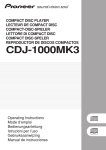
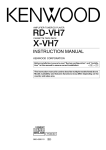
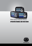
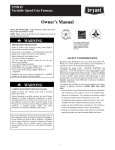
1
DJ MIXER
DJM-909
Operating Instructions
1
<DRB1349>
Thank you for buying this Pioneer product.
Please read through these operating instructions so you will
know how to operate your model properly. After you have
finished reading the instructions, put them away in a safe place
for future reference.
In some countries or regions, the shape of the power plug and
power outlet may sometimes differ from that shown in the
explanatory drawings. However the method of connecting and
operating the unit is the same.
K015 En
NOTE: THE NO USER-SERVICEABLE PARTS COMPARTMENT WARNING IS LOCATED ON THE APPLIANCE BOTTOM.
2
<DRB1349>
IMPORTANT NOTICE
The serial number for this equipment is located on the bottom
plate. Please write this serial number on your enclosed
warranty card and keep it in a secure area. This is for your
security.
WARNING:
Handling the cord on this product or cords associated with
accessories sold with the product will expose you to lead, a
chemical known to the State of California and other
governmental entities to cause cancer and birth defects or
other reproductive harm.
Wash hands after handling.
3
<DRB1349>
CONTENTS
FEATURES
CAUTIONS REGARDING HANDLING ...................... 4
Location ........................................................................... 4
Condensation .................................................................. 4
Cleaning the Unit ............................................................ 4
FEATURES .................................................................
CHECKING ACCESSORIES .......................................
CONNECTIONS .........................................................
PART NAMES AND FUNCTIONS .............................
4
5
5
7
Top Panel ........................................................................ 7
Front Panel .................................................................... 12
Rear Panel ..................................................................... 13
Touch Panel Display Contents ...................................... 14
Touch Panel Display Selection ...................................... 15
BPM COUNTING ..................................................... 16
FADER OPERATIONS .............................................. 17
EFFECT FUNCTIONS ............................................... 19
Types of Effects ............................................................ 19
Using the Effect Functions ........................................... 22
Presetting Effects ......................................................... 23
Effect Parameters ......................................................... 24
TROUBLESHOOTING .............................................. 27
SPECIFICATIONS .................................................... 28
CAUTIONS REGARDING HANDLING
Location
Install the unit in a well-ventilated location where it will
not be exposed to high temperatures or humidity.
÷ Do not install the unit in a location which is exposed to
direct rays of the sun, or near stoves or radiators.
Excessive heat can adversely affect the cabinet and
internal components. Installation of the unit in a damp or
dusty environment may also result in a malfunction or
accident. (Avoid installation near cookers etc., where the
unit may be exposed to oily smoke, steam or heat.)
÷ When the unit is used inside a carrying case or DJ booth,
separate it from the walls or other equipment to improve
heat radiation.
Condensation
When this unit is brought into a warm room from previously
cold surroundings or when the room temperature rises
sharply, condensation may form inside, and the unit may not
be able to attain its full performance. In cases like this, allow
the unit to stand for about an hour or raise the room
temperature gradually.
Cleaning the Unit
÷ Use a polishing cloth to wipe off dust and dirt.
÷ When the surfaces are very dirty, wipe with a soft cloth
dipped in some neutral cleanser diluted five or six times
with water and wrung out well, then wipe again with a dry
cloth. Do not use furniture wax or cleaners.
÷ Never use thinners, benzene, insecticide sprays or other
chemicals on or near this unit, since these will corrode the
surfaces.
4
<DRB1349>
1) Designed for high sound quality
Electronic parts have been carefully selected and internal
circuitry redesigned to provide the shortest-possible signal
paths, thus realizing true club sound with power to spare.
2) Effects create new performance potential
1 50 effects in 2 systems: Each channel can be preset with
three of 50 possible effects. Sequential effects can be
called up seamlessly merely by touching the names of the
effects on the top panel’s LCD touch panel, creating a new
level of DJ performances.
2 Fader effects: an industry first, Pioneer’s “fader effects”
allow the user to change effect parameters by operating
the sliders for the cross fader or channel fader, thus
providing greater operating facility compared to
conventional rotating dials, while also allowing the DJ to
apply scratch sounds to effects and create other new
remix performances.
3 Beat effects: linked to track tempo (BPM: beats per
minute), “beat effects” allow the user to apply echo, delay
and other effects with perfect timing.
4 Effect frequency selection: effects can be targeted at HI,
MID, and LOW frequency ranges as desired; simultaneous
multiple frequency ranges can also be specified.
3) Ergonomic, user-customizable cross fader
1 Cross-fader “feeling” adjustment: the specific physical
sensation of cross fader operation is all-important to the
DJ; the “feeling” adjustment provided in this mixer is an
industry first, allowing the user to adjust the physical
sensation of the slider to personal preferences, for the
smoothest possible cross fader operation.
2 Independent cross fader lag cut: the mechanical play
(the lag distance before sound begins) at each end of the
cross fader slider can be adjusted using the fader lag cut
function, thus allowing adjustment of the sound cut when
performing scratch play.
3 Independent cross fader curve: an industry first, the
right-left independently adjustable (33 steps) cross fader
curve control goes beyond the symmetrical type of cross
fader curve on conventional mixers, thus broadening DJ
performance capabilities.
4 “Contactless fader” mechanism: based on Pioneer’s
own proprietary technology, this new contactless optical
fader assures durable and stable operation under the
severest of DJ performance conditions.
4) Touch-panel display provides both wide
information and ease of operation
The top panel LCD display includes a fader edit monitor that
displays information about user fader settings (curve, reverse,
cut lag, etc.) together with other information necessary for
remix and DJ play. The use of a touch panel also makes it
possible to select effects easily with a single touch.
5) Other features
1 An industry first for DJ mixers, this unit supports use of an
optional foot switch to allow quick ON/OFF control of
effects.
2 When connected via a control cord to a Pioneer DJ CD
player (sold separately), operation of the fader can be used
for automatic “fader start” play.
3 “Fader reverse” function allows reversing of the
directions of fader operation movement.
4 Delicate 33-step channel fader curve settings.
5 Can be connected in series to other mixers for “session”
output of mixed sounds.
CHECKING ACCESSORIES
÷
÷
÷
Hexagonal Allen driver
(for cross fader operating load adjust screw)
These operating instructions
Warranty
CONNECTIONS
When connecting or changing the connection of units, make sure to first turn off the power switch and disconnect the power cord
from the outlet.
This mixer is not furnished with any connection cables; when performing connections, use the cables that came provided with your
player and other components, or purchase commercially available audio cables.
1. Connecting Input Components
[DJ CD Player]
CDJ-800, CDJ-1000, CDJ-1000MK2,
CDJ-100S, CDJ-700S, CDJ-500II,
CMX-3000, CMX-5000, DMP-555
Analog turntable 2
Analog turntable 1
Player A
Player B
Cassette deck, etc.
Cassette deck, etc.
1
2
1
2
Microphone
R L
R L
CONTRAST
R
CH-2
R
L
SEND
BRIGHT
L
R
RETURN
L
R
MASTER 2
L
PHONO
/ LINE
R
(MONO)
SIGNAL
GND
CH-1
L
(MONO)
3
MIC
PHONO
/ LINE
MASTER 1
PHONO
BOOTH/
SESSION OUT
R
CD
CD
L
R L
R
LINE
CH-2 PLAYER
CONTROL
R
2 HOT
L
PHONO
3 COLD
1 GND
L
CH-1 PLAYER
CONTROL
SIGNAL
GND
L
LINE
SESSION IN
R
4
CH-2 PHONO/LINE
selector switch
DJ CD Players 1
Connect the AUDIO OUT connectors from Player A to the
CH-1 CD input jacks of the DJ mixer, and connect the AUDIO
OUT connectors from Player B to the CH-2 CD input jacks.
When using one of the listed DJ CD players, the control cord
furnished with the CD player should be connected between
the player and the DJ mixer. In this way, the DJ mixer’s fader
lever can be operated to control operation of the DJ CD
player for fader start play and back cue.
CH-1 PHONO/LINE
selector switch
Other mixer output
Connect the analog turntable 2 output cables to the CH-2
PHONO/LINE jacks of the DJ mixer, and connect the ground
wire to the SIGNAL GND terminal. Set the CH-2 PHONO/
LINE selector switch to [PHONO]. When connecting a
cassette deck or other such component to these jacks, set
the CH-2 PHONO/LINE selector switch to [LINE].
* The PHONO input for this DJ mixer supports use of a MM
cartridge.
MIC 3
Analog turntable / Cassette deck, etc. 2
Connect the analog turntable 1 output cables to the CH-1
PHONO/LINE jacks of the DJ mixer, and connect the ground
wire to the SIGNAL GND terminal. Set the CH-1 PHONO/
LINE selector switch to [PHONO]. When connecting a
cassette deck or other such component to these jacks, set
the CH-1 PHONO/LINE selector switch to [LINE].
The MIC jack on this unit supports use of either PHONE type
or XLR type plugs.
SESSION IN 4
When using multiple mixers simultaneously, use the
appropriate audio cables to connect the other mixer outputs
to these jacks.
5
<DRB1349>
CONNECTIONS
2. Connecting Foot Switch and Headphones (front panel)
Headphones
FADER REVERSE
CH-1
5
C.F.
FADER START
CH-2
C.F. 1 CH-1
ON
ON
ON
OFF
OFF
OFF
PHONES
C.F. 2 CH-2
PROFESSIONAL 2CHANNEL MIXER
6
DJM-909
FADER CURVE
CH-1
FOOT SW
CROSS FADER 1
POWER
CROSS FADER 2
CH-2
FADER CUT LAG
CH-1
OFF
MIN
Foot switch
(pedal switch)
MAX
CH-2
Foot switch 5
Headphones 6
Allows the connection of a foot switch with a 6.3 mm
monaural plug. The foot switch control effect ON/OFF.
Use to connect headphones with a 6.3 mm diameter stereo
plug.
3. Output Connections
External effector
Power amplifier
(supporting RCA input)
7
CONTRAST
9
L
R
CH-2
SEND
R
L
BRIGHT
L
R
RETURN
L
R
R
p
MASTER 2
L
L
(MONO)
PHONO
/ LINE
R
(MONO)
CH-2 PLAYER
CONTROL
R
MIC
L
R
PHONO
L
2 HOT
CH-1 PLAYER
CONTROL
SIGNAL
GND
LINE
8
L
R
Power amplifier
(for booth monitor)
L
PHONO
/ LINE
3 COLD
1 GND
LINE
BOOTH/
SESSION OUT
CH-1
MASTER 1
PHONO
SIGNAL
GND
R
CD
CD
SESSION IN
Power amplifier
(supporting XLR input)
q
Power cord
Power outlet
To SESSION IN jacks of other mixer
External effector 7
Use a 6.3 mm monaural plug to connect the external
effector’s input connectors to the DJ mixer’s SEND jacks.
When using an effector with a monaural input, connect it to
the L channel output only. The signal actually sent to the
effector will represent a mix of L and R signals.
Use a 6.3 mm monaural plug to connect the external effector’s
output connectors to the DJ mixer’s RETURN jacks.
When using an effector with monaural output, connect only
the L channel input. The signal received from the effector will
be input to both L and R channels.
MASTER 2 9
RCA type unbalanced output.
BOOTH/SESSION OUT p
These jacks are provided for booth monitor output.
The sound volume here is controlled by the booth monitor
level dial, regardless of the setting of the MASTER LEVEL
dial.
When using this unit in tandem with another mixer, connect
these jacks to the other mixer’s session input connectors.
Power cord q
Master output
MASTER 1 8
XLR type balanced output.
6
<DRB1349>
After completing all other connections, connect the power
plug to a standard power outlet or to the auxiliary power
outlet of an amplifier.
PART NAMES AND FUNCTIONS
Top Panel (1)
2
1
10 11
MIC
PHONO 1
/LINE 1 CD 1
BANK 1
BANK 1
BANK 2
BANK 2
CH-1
PHONO 2
/LINE 2 CD 2
MASTER LEVEL
MIC LEVEL
TRIM
3
TRIM
BANK 3
BOOTH/SESSION OUT
BANK 3
+9
–
13
HI
FX ADJ.
+12
-12
+9
–
HI
FX ADJ.
PHONES
+6
-26
MID
-12
5
0
–
LOW
4
0
–
HI
FADER
CURVE
FADER
CURVE
14
+6
-26
MID
0
–
+12
BANK
EDIT
BANK
EDIT
MIC SEND
SELECT
MASTER
PROFESSIONAL 2CHANNEL MIXER
+6
-26
6
TIME/SELECT
LOW
DJM-909
TIME/SELECT
+6
-26
EFFECT
LOW
EFFECT
16
EFFECT
LOCK ON
+6
-26
MIX/DEPTH
CH-1
MIX/DEPTH
OFF
CH-2
+6
-26
ON
0
–
CH-1 SEND
EQ
17
EQ
OFF
OFF
MIN
8
MAX
ON
TAP
TAP
MIN
CH-2 SEND
MAX
18
ON
9
19
TRANSFORM
FADER START
TRANSFORM
20
21
MASTER LEVEL
REVERSE
L
14
9
9
10
5
5
10
9
3
3
9
8
1
1
8
0
0
– 1
–1
– 3
–3
3
– 6
–6
3
2
– 9
–9
2
1
– 15
– 15
1
0
– 22
dB
– 22
dB
0
7
6
5
CH-1 FADER START
4
CH-2 FADER START
31
32
33
34
35
C.F.2 FADER START
36
R
14
CH-1
CH-1
25
26
FADER START
30
REVERSE
22
23
24
15
CUE
SESSION IN
7
12
0
–
CH-2
7
6
5
4
CH-2
REVERSE
C.F.1 FADER START
1
2
FEELING
ADJ.
PHONES
POWER
FOOT SW
27
1 CH-1 input selector switch
(MIC – PHONO 1/LINE 1 – CD 1)
Use to select input signal from MIC jack, CH-1 PHONO/LINE
input jacks, or CH-1 CD input jacks, and send them to the
TRIM control.
* When [MIC] is selected, the MIC signals are sent directly to
the TRIM section without passing through the microphone
level and microphone equalizer circuits.
2 CH-1 TRIM dial
Use to adjust the CH-1 input signal level (range of
adjustment: +9 dB to –∞).
28
29
3 Microphone level dial (MIC LEVEL)
Use to adjust the microphone level (range of adjustment:
0 dB to –∞).
4 Microphone equalizer dials (HI/LOW)
HI
Use to adjust microphone treble response (range of
adjustment: 10 kHz, ±12 dB).
LOW
Use to adjust microphone bass response (range of
adjustment: 100 Hz, ±12 dB).
7
<DRB1349>
PART NAMES AND FUNCTIONS
5 CH-1 equalizer dials (HI/MID/LOW)
15 Monitor SELECT switch
HI
Use to adjust CH-1 input treble response (range of adjustment:
13 kHz, +6 dB to –26 dB).
MID
Use to adjust CH-1 input midrange response (range of
adjustment: 1 kHz, +6 dB to –26 dB).
LOW
Use to adjust CH-1 input bass response (range of adjustment:
70 Hz, +6 dB to –26 dB).
MASTER position
selects MASTER output. (This setting allows output
regardless of the setting of the MASTER LEVEL dial.)
EFFECT position
Regardless of the [ON/OFF] setting of the EFFECT switch,
the output is the signal selected with CUE, with effects
added.
CUE position
selects the channel adjusted with the headphone mixing
lever (17).
6 MIC SEND button and indicator
When set to On, the indicator lights, and microphone signals
are output at the SEND jacks. This function is disabled when
the CH-1 input selector switch is set to [MIC].
7 Session input level dial (SESSION IN)
Use to adjust the session input volume (range of adjustment:
0 dB to –∞).
8 CH-1 SEND button and indicator
When set to On, the indicator lights, and CH-1 signals are
output at the SEND jacks.
9 CH-1 EQ ON/OFF switch and indicator
When set to [ON], the indicator lights and CH-1 equalizer is
enabled.
When set to [OFF], the indicator goes out and the equalizer
circuit is bypassed.
10 CH-2 input selector switch
(CH-1 – PHONO 2/LINE 2 – CD 2)
Use to select input signal from CH-1 (component selected
with CH-1 input selector switch), CH-2 PHONO/LINE input
jacks, or CH-2 CD input jacks, and send them to the TRIM
control.
* When [CH-1] is selected, signals are sent to the CH-2 TRIM
control without being sent through the CH-1 TRIM control.
11 CH-2 TRIM dial
Use to adjust the CH-2 input signal level (range of
adjustment: +9 dB to –∞).
12 MASTER LEVEL dial
User to adjust the master output volume level (range of
adjustment: 0 dB to –∞).
13 Booth monitor level dial
(BOOTH/SESSION OUT)
Use to adjust the volume level of signals at the BOOTH/
SESSION OUT jacks (range of adjustment: 0 dB to –∞).
This level can be set independently of the setting of the
MASTER LEVEL dial.
14 Headphones level dial (PHONES)
Use to adjust the volume level of the headphones output
(range of adjustment: 0 dB to –∞).
8
<DRB1349>
16 CH-2 equalizer dials (HI/MID/LOW)
HI
Use to adjust CH-2 input treble response (range of
adjustment: 13 kHz, +6 dB to –26 dB).
MID
Use to adjust CH-2 input midrange response (range of
adjustment: 1 kHz, +6 dB to –26 dB).
LOW
Use to adjust CH-2 input bass response (range of
adjustment: 70 Hz, +6 dB to –26 dB).
17 Headphone mixing lever (CH-1 – CH-2)
This lever does not function when the monitor SELECT
switch (15) is set to [MASTER].
When the monitor SELECT switch (15) is set to [EFFECT] or
[CUE], moving the lever to the left side produces CH-1
monitor output, while moving it to the right produces CH-2
monitor output. Centering the lever at the center detent
position produces balanced output of CH-1 and CH-2 signals.
18 CH-2 SEND button and indicator
When set to On, the indicator lights, and CH-2 signals are
output at the SEND jacks.
19 CH-2 EQ ON/OFF switch and indicator
When set to [ON], the indicator lights and the CH-2 equalizer
is enabled.
When set to [OFF], the indicator goes out and the equalizer
circuit is bypassed.
20 CH-1 FADER START button
When this button is set to On, fader start and back cue can be
performed on the CH-1 CD player.
Whether the operation is initiated by operation of the CH-1
fader lever, or by the cross fader lever is determined by the
position of the front panel’s FADER START selector switch;
the selection is indicated by the lighting of the top panel’s
CH-1 FADER START indicator or C.F.1 FADER START
indicator.
* For DJ CD players supporting the fader start/back cue
function, see page 5, “1. Connecting Input Components”.
21 CH-1 output On/Off lever (TRANSFORM)
Use to set CH-1 output to On or Off (Mute).
The lever’s setting angle can be changed in 45° increments
(changing of the angle should be performed by an authorized
Pioneer service technician).
PART NAMES AND FUNCTIONS
22 CH-1 REVERSE indicator
32 CH-2 REVERSE indicator
When lighted, indicates that the front panel’s FADER
REVERSE switch has been set so that the CH-1 fader lever
operates in the reverse direction (see front panel item 52).
When lighted, indicates that the front panel’s FADER
REVERSE switch has been set so that the CH-2 fader lever
operates in the reverse direction (see front panel item 52).
23 CH-1 fader lever
33 MASTER LEVEL display button and indicator
The CH-1 fader lever is used to control the level of signals
sent to the cross fader. Signal level is maximum at scale mark
“10,” and minimum at scale mark “0”.
When the front panel CH-1 FADER REVERSE switch is set to
[ON], the signal level is maximum at scale mark “0,” and
minimum at scale mark “10”.
* The channel fader curve can be adjusted by means of the
front panel FADER CURVE dials.
When depressed to the On position, the indicator lights and
the level meters display the master output (stereo) peak
levels. When turned Off, the level meters display the peak
levels for CH-1 (left) and CH-2 (right) (see also item 26).
34 CH-2 fader lever
25 C.F.1 FADER START indicator
The CH-2 fader lever is used to control the level of signals
sent to the cross fader. Signal level is maximum at scale mark
“10,” and minimum at scale mark “0”.
When the front panel CH-2 FADER REVERSE switch is set to
[ON], the signal level is maximum at scale mark “0,” and
minimum at scale mark “10”.
* The channel fader curve can be adjusted by means of the
front panel FADER CURVE dials.
Lights when CH-1 cross-fader start/back cue function is
enabled (see also top panel item 20 and front panel item 53).
35 CH-2 FADER START indicator
26 Level meters
Lights when the CH-2 fader start/back cue function is
enabled (see also top panel item 30 and front panel item 53).
Displays CH-1 and CH-2 peak levels or master output (stereo)
peak levels (see also item 33).
36 C.F.2 FADER START indicator
27 Cross fader REVERSE indicator
Lights when CH-2 cross-fader start/back cue function is
enabled (see also top panel item 30 and front panel item 53).
24 CH-1 FADER START indicator
Lights when the CH-1 fader start/back cue function is
enabled (see also top panel item 20 and front panel item 53).
Indicates that the front panel’s FADER REVERSE switch has
been set so that the cross fader now operates in reverse (left
side is CH-2, right side is CH-1) (see also front panel item 52).
28 Cross fader lever
When the lever is moved to the left side, CH-1 is at maximum
output and CH-2 is at minimum. When moved to the right
side, CH-2 is at maximum output and CH-1 is at minimum.
* The cross fader curve can be adjusted individually for CH-1
and CH-2 by means of the front panel FADER CURVE dials.
29 Operating load adjust screw (FEELING ADJ.)
The hexagonal Allen screw located next to the panel’s slider
opening can be rotated with a hexagonal Allen driver to adjust
the sliding resistance of the cross fader lever. (See page 17,
“Operating load adjust screw”.)
30 CH-2 FADER START button
When this button is set to On, fader start and back cue can be
performed on the CH-2 CD player.
Whether the operation is initiated by operation of the CH-2
fader lever, or by the cross fader lever is determined by the
position of the front panel’s FADER START selector switch;
the selection is indicated by the lighting of the top panel’s
CH-2 FADER START indicator or C.F.2 FADER START
indicator.
* For DJ CD players supporting the fader start/back cue
function, see page 5, “1. Connecting Input Components”.
31 CH-2 output On/Off lever (TRANSFORM)
Use to set CH-2 output to On or Off (Mute).
This lever’s setting angle can be changed in 45° increments
(changing of the angle should be performed by an authorized
Pioneer service technician).
9
<DRB1349>
PART NAMES AND FUNCTIONS
Top Panel (2)
37
MIC
PHONO 1
/LINE 1 CD 1
BANK 1
BANK 1
BANK 2
BANK 2
PHONO 2
CH-1 /LINE 2 CD 2
MASTER LEVEL
MIC LEVEL
TRIM
TRIM
45
38
0
–
BANK 3
BOOTH/SESSION OUT
BANK 3
+9
–
HI
FX ADJ.
+12
-12
+9
–
HI
FX ADJ.
PHONES
+6
-26
MID
40
-12
0
–
LOW
39
0
–
HI
FADER
CURVE
FADER
CURVE
MID
0
–
+12
BANK
EDIT
BANK
EDIT
MIC SEND
TIME/SELECT
LOW
DJM-909
47
SELECT
MASTER
PROFESSIONAL 2CHANNEL MIXER
+6
-26
46
+6
-26
TIME/SELECT
+6
-26
EFFECT
LOW
CUE
41
EFFECT
SESSION IN
48
EFFECT
LOCK ON
+6
-26
MIX/DEPTH
CH-1
MIX/DEPTH
OFF
CH-2
+6
-26
ON
42
–
0
CH-1 SEND
EQ
EQ
OFF
OFF
MIN
MAX
ON
43
TAP
TAP
MIN
CH-2 SEND
49
MAX
ON
50
51
44
FADER START
TRANSFORM
37 Touch Panel
Touch this screen to set effects in accordance with the
displayed menus.
* The panel’s screen contrast and backlight luminance can
be adjusted (see rear panel items 61 and 63).
TRANSFORM
FADER START
40 Fader curve display and CH-1 effect select
button (FADER CURVE/BANK EDIT)
Press to display the fader curve on the touch panel. Holding
the button depressed for about one second will cause the
touch panel to display the CH-1 effect select menu.
38 CH-1 effect bank buttons and indicators
(BANK 1, 2, 3)
41 CH-1 effect time adjust/select dial
(TIME/SELECT)
When one of these buttons is pressed, the indicator lights
and the corresponding preset effect is enabled. Each BANK
button can be recorded with three effects for CH-1 (at time of
shipping, the buttons have been factory preset with typically
used effects). BANK 1 is selected in the default condition
after power is initially turned on.
Use to adjust the time parameters of effects applied to CH-1
(rotate clockwise to lengthen, counterclockwise to shorten).
When the effect select menu is displayed, causes the effects
list to scroll.
39 CH-1 effect parameter adjust button (FX ADJ.)
Press to display the touch panel’s CH-1 effect parameter
adjust menu.
10
<DRB1349>
42 CH-1 effect mix ratio/depth adjust dial
(MIX/DEPTH)
Use to adjust the volume (amount) of effects applied to CH-1
(rotate clockwise to increase effects, counterclockwise to
reduce).
PART NAMES AND FUNCTIONS
43 CH-1 effect switch and indicator
(EFFECT LOCK ON/OFF/ON)
49 CH-2 effect mix ratio/depth adjust dial
(MIX/DEPTH)
To turn effects [ON], either pull switch forward (switch
returns automatically to [OFF] when released) or slide to far
side to the [LOCK ON] position. When effects are [ON], the
indicator flashes and effects are applied to CH-1.
Use to adjust the volume (amount) of effects applied to CH-2
(rotate clockwise to increase effects, counterclockwise to
reduce).
44 CH-1 TAP button
Under normal conditions, the automatic BPM counter
operates to display the track’s BPM value on the touch panel.
Automatic BPM counting may be difficult with some tracks,
however. In such cases, or if you wish to deliberately set a
different BPM, use the TAP button.
• The BPM value can be changed by rotating the TIME/
SELECT dial while holding the TAP button depressed.
• Tapping the button in time with the beat will cause the
function to switch to the manual BPM count mode; the
tapped beat will be counted and displayed as the BPM
value. Returning to the auto BPM mode is performed from
the effect parameter adjust screen (see page 16,
“Automatic Mode BPM Counting”) .
45 CH-2 effect bank buttons and indicators
(BANK 1, 2, 3)
When one of these buttons is pressed, the indicator lights
and the corresponding preset effect is enabled. Each BANK
button can be recorded with three effects for CH-2 (at time of
shipping, the buttons have been factory preset with typically
used effects). BANK 1 is selected in the default condition
after power is initially turned on.
50 CH-2 effect switch and indicator
(EFFECT LOCK ON/OFF/ON)
To turn effects [ON], either pull switch forward (switch
returns automatically to [OFF] when released) or slide to far
side to the [LOCK ON] position. When effects are [ON], the
indicator flashes and effects are applied to CH-2.
51 CH-2 TAP button
Under normal conditions, the automatic BPM counter
operates to display the track’s BPM value on the touch panel.
Automatic BPM counting may be difficult with some tracks,
however. In such cases, or if you wish to deliberately set a
different BPM, use the TAP button.
• The BPM value can be changed by rotating the TIME/SELECT
dial while holding the TAP button depressed.
• Tapping the button in time with the beat will cause the
function to switch to the manual BPM count mode; the
tapped beat will be counted and displayed as the BPM
value. Returning to the auto BPM mode is performed from
the effect parameter adjust screen (see page 16,
“Automatic Mode BPM Counting”) .
46 CH-2 effect parameter adjust button (FX ADJ.)
Press to display the touch panel’s CH-2 effect parameter
adjust menu.
47 Fader curve display and CH-2 effect select
button (FADER CURVE/BANK EDIT)
Press to display the fader curve on the touch panel. Holding
the button depressed for about one second will cause the
touch panel to display the CH-2 effect select menu.
48 CH-2 effect time adjust/select dial
(TIME/SELECT)
Use to adjust the time parameters of effects applied to CH-2
(rotate clockwise to lengthen, counterclockwise to shorten).
When the effect select menu is displayed, causes the effects
list to scroll.
11
<DRB1349>
PART NAMES AND FUNCTIONS
Front Panel
52
53
FADER REVERSE
CH-1
C.F.
FADER START
CH-2
C.F. 1 CH-1
ON
ON
ON
OFF
OFF
OFF
54
PROFESSIONAL 2CHANNEL MIXER
DJM-909
FADER CURVE
CH-1
FOOT SW
PHONES
C.F. 2 CH-2
CROSS FADER 1
POWER
CROSS FADER 2
CH-2
55
FADER CUT LAG
CH-1
OFF
MIN
MAX
CH-2
58
57
56
52 FADER REVERSE switches
54 Headphone output jack (PHONES)
CH-1 ON/OFF
When set to [ON], the top panel’s CH-1 REVERSE indicator
lights, and the CH-1 fader lever operates in the reverse
direction (scale mark “0” becomes 0 dB attenuation, and
“10” becomes minus infinity). The fader start function also
operates in reverse.
CH-2 ON/OFF
When set to [ON], the top panel’s CH-2 REVERSE indicator
lights, and the CH-2 fader lever operates in the reverse
direction (scale mark “0” becomes 0 dB attenuation, and
“10” becomes minus infinity). The fader start function also
operates in reverse.
C.F. ON/OFF
When set to [ON], the top panel’s cross fader REVERSE
indicator lights, and the cross fader lever operates in the
reverse direction (left side becomes CH-2, and right side
becomes CH-1). The fader start function also operates in
reverse.
Accepts a 6.3 mm stereo headphones plug.
53 FADER START selector switches
C.F.1 / CH-1
This switch determines whether the fader start operation for
the CD player connected to CH-1 is activated by the cross
fader lever, or by the CH-1 fader lever.
When the top panel’s CH-1 FADER START button is set to
On, selecting [C.F.1] causes the top panel’s C.F.1 FADER
START indicator to light, and selecting [CH-1] causes the top
panel’s CH-1 FADER START indicator to light.
C.F.2 / CH-2
This switch determines whether the fader start operation for
the CD player connected to CH-2 is activated by the cross
fader lever, or by the CH-2 fader lever.
When the top panel’s CH-2 FADER START button is set to
On, selecting [C.F.2] causes the top panel’s C.F.2 FADER
START indicator to light, and selecting [CH-2] causes the top
panel’s CH-2 FADER START indicator to light.
12
<DRB1349>
55 POWER switch
56 Fader attenuation dials (FADER CURVE)
CH-1
Use to adjust CH-1’s fader attenuation curve.
CH-2
Use to adjust CH-2’s fader attenuation curve.
CROSS FADER 1
Use to adjust cross fader’s CH-1 attenuation curve.
CROSS FADER 2
Use to adjust cross fader’s CH-2 attenuation curve.
FADER CUT LAG
Use to adjust mechanical play at both extremes of the cross
fader movement (the range in which lever movement
produces no effect).
(See page 17, “Fader attenuation curve adjustment”.)
57 Foot switch channel select switch
(FOOT SW CH-1/OFF/CH-2)
Use to select whether the Effect On/Off foot switch function
operates on channel 1 [CH-1], channel 2 [CH-2]. When the
switch is in the center position, both CH-1 and CH-2 are
[OFF].
58 Foot switch jack (FOOT SW)
This 6.3 mm RCA jack can be used to connect an On/Off type
pedal switch used to turn effects On and Off.
Various types of foot switch are available; some turn On
when pressed, some turn Off when pressed, and others
have locking mechanisms (alternate On/Off with successive
presses). Select the type in accordance with your own
preferences.
PART NAMES AND FUNCTIONS
Rear Panel
59
60
61 62
CONTRAST
R
CH-2
SEND
R
L
63
64
BRIGHT
L
RETURN
R
L
R
R
MASTER 2
L
(MONO)
PHONO
/ LINE
SIGNAL
GND
(MONO)
MIC
PHONO
/ LINE
R
CH-2 PLAYER
CONTROL
73 72
71
R
2 HOT
70
L
66
PHONO
3 COLD
1 GND
LINE
BOOTH/
SESSION OUT
L
MASTER 1
PHONO
74
CH-1
CD
CD
75
65
L
CH-1 PLAYER
CONTROL
69
SIGNAL
GND
LINE
SESSION IN
68 67
59 CH-2 input jacks
67 CH-1 PHONO/LINE selector switch
CD
Connect to audio output from CH-2 CD player.
PHONO / LINE
Connect to audio output from CH-2 analog turntable,
cassette deck or other line signal level component.
Use to set the input sensitivity at the CH-1 PHONO/LINE
connectors. The [PHONO] position supports an MM type
cartridge.
* When no analog turntable is used, set this switch to the
[LINE] side.
60 External effector output jacks (SEND)
68 CH-1 signal ground (SIGNAL GND)
Connect to the input connectors of an external effector.
When the top panel switches (MIC SEND, CH-1 SEND, and
CH-2 SEND) are set to On, these jacks output the MIC, CH-1,
and CH-2 signals to the external effector.
When using an effector with a monaural input, connect it to
the L channel output only. The signal actually sent to the
effector will represent a mix of L and R signals.
Connect to the CH-1 analog turntable’s ground wire. Note
that this is not meant as a safety ground.
69 CH-1 PLAYER CONTROL jack
61 Touch panel screen contrast control (CONTRAST)
70 MASTER 1 jacks
Use to adjust the top panel’s touch panel contrast.
XLR type balanced output. Connect to the power amplifier’s
balanced input jacks.
When a Pioneer DJ CD player is connected to the CH-1 CD
jacks, a special control cord can be used to connect this jack to
the player’s control jack, thus enabling the fader start function.
62 External effector return jacks (RETURN)
Connect to the output connectors of the external effector.
When using an effector with monaural output, connect only
to the L channel input. The signal received from the effector
will be input to both L and R channels.
71 CH-2 PLAYER CONTROL jack
63 Touch panel backlight control (BRIGHT)
72 CH-2 PHONO/LINE selector switch
Use to adjust the top panel’s touch panel backlight
luminance.
Use to set the input sensitivity at the CH-2 PHONO/LINE
connectors. The [PHONO] position supports an MM type
cartridge.
* When no analog turntable is used, set this switch to the
[LINE] side.
64 CH-1 input jacks
When a Pioneer DJ CD player is connected to the CH-2 CD
jacks, a special control cord used to connect this jack to the
player’s control jack, thus enabling the fader start function.
CD
Connect to the audio output of the CH-1 CD player.
PHONO / LINE
Connect to audio output from CH-1 analog turntable,
cassette deck or other line signal level component.
73 CH-2 signal ground (SIGNAL GND)
65 Microphone input jack (MIC)
74 BOOTH/SESSION OUT jacks
Connect to a microphone with XLR type or PHONE type plug.
When applying effects to the microphone sound, set the top
panel’s CH-1 input selector switch (MIC–PHONO 1/LINE 1–
CD1) to the [MIC] position.
Connector jacks for booth monitor output. When using this
unit in tandem with another mixer, connect these jacks to the
other mixer’s session input jacks.
Connect to the CH-2 analog turntable’s ground wire. Note
that this is not meant as a safety ground.
75 MASTER 2 jacks
66 Session input jacks (SESSION IN)
When using multiple mixers simultaneously, connect the
other mixer outputs to these jacks.
RCA type unbalanced output. Connect to the power
amplifier’s unbalanced input jacks.
13
<DRB1349>
PART NAMES AND FUNCTIONS
Touch Panel Display Contents
BANK 1
B. Effect select display
BANK 1
BANK 2
EDIT 1 CH FOOT
TIME 2000 ms
EDIT 2 CH
PICH
LOW MID HI
LOW MID HI
AUTO
AUTO
120 BPM
0%
BANK 2
120 BPM
BANK 3
BANK 3
FX ADJ.
FX ADJ.
FADER
CURVE
FADER
CURVE
BANK
EDIT
Hold the FADER CURVE/BANK EDIT button depressed for
about one second to change the screen to the main page
effect select menu (settable independently for each channel).
Rotate the TIME/SELECT dial to select the effect to be
allocated to each button from the list of 50 effects displayed
(see page 23, “Presetting effects”).
Effect list (ECHO)
(Example): CH-1 side.
≠
CH 1 BANK EDIT
BANK
EDIT
PROFESSIONAL 2CHANNEL MIXER
TIME/SELECT
DJM-909
EFFECT
TIME/SELECT
EFFECT
LOCK ON
MIX/DEPTH
1 . DE L AY
2 . ECHO
3 . PAN EC
4 . P I T EC
5 . RV DL Y
6 . DK EC
7 . ROL L
The button being
=
edited (here, ECHO)
appears highlighted.
MIX/DEPTH
OFF
ON
MIN
MAX
TAP
TAP
MIN
MAX
The touch panel display has four basic patterns (A-D). The
screen contents shown in the accompanying illustrations
depict one example of the basic patterns, while actual
displays may differ, depending on the kind of settings and
status involved.
A. Effect type display (main page)
This display appears when the power is first turned on, or
when one of the BANK (1-3) buttons is pressed.
The effects for each channel are displayed as buttons, with
the currently selected button displayed in reverse
illumination (in this manual, indicated as black characters
against white background). Other displays show status of
foot switch, selected effect parameters, frequency bands
subject to effects, TIME display and BPM display.
FOOT
ms
BPM
%
BPM
Press the FX ADJ. button to display the effect parameter
adjust menu (settable independently for each channel). From
this menu, BPM AUTO can be selected. Also, effect
selection (cross fader / channel fader) can be selected for
fader type.
ECHO
Select frequency band
for effect (HI, MID,
=
LOW).
CH1
TIME
AUTO
120 BPM
FOOT
2000 ms
Select effect
=
parameter (4/1).
±
Select method of BPM
count (BPM AUTO).
D. Fader status display
Press the FADER CURVE/BANK EDIT button to view the
fader status in a graphic display. By rotating the front panel
FADER CURVE dial, the various attenuation responses can
be set in 33 steps, and each step number also displayed. The
amount of cross fader lag is also given a numerical display.
FADER CURVE
16 CH 2
16
CH 1
CF 1
NORMAL
32
CF 2
NORMAL
CH-1 fader data =
NORMAL
CH-1 side EFFECT + | = CH-2 side EFFECT
When a foot switch is
EDIT 2 CH
EDIT 1 CH
TIME 2000
PICH
0
connected, FOOT is
LOW MID HI LOW MID HI
AUTO 1 2 0
AUTO 1 2 0
displayed.
The frequency band
subjected to effects is
highlighted (HI, MID,
LOW).
BPM count method is
displayed (AUTO).
Currently selected
effect is highlighted
(ECHO, PITCH
SHIFTER).
C. Effect parameter adjust display
32
+ Cross fader
data
FADER CUT LAG : 1 .0 mm
±
Cross fader lag data
(FADER CUT LAG)
14
<DRB1349>
+ CH-2 fader
data
PART NAMES AND FUNCTIONS
Touch Panel Display Selection
Changing between the touch panel’s four basic display
patterns (A, B, C, D) is performed by pressing the operating
buttons at the panel’s sides.
Effect parameter adjust
B Effect select display
C display
ECHO
CH 1 BANK EDIT
FADER
CURVE
Hold FADER CURVE/BANK
EDIT button depressed.
BANK
EDIT
CH1
AUTO
1 2 0 BPM
TIME
FOOT
2 0 0 0 ms
Hold FADER CURVE/
BANK EDIT button
Press FX ADJ.
depressed.
Effect type display button.
FADER
CURVE
(main page)
FX ADJ.
1 . DE L AY
2 . ECHO
3 . PAN EC
4 . P I T EC
5 . RV DL Y
6 . DK EC
7 . ROL L
A
BANK
EDIT
FADER
CURVE
EDIT 1 CH FOOT
TIME 2 0 0 0 ms
EDIT 2 CH
PICH
LOW MID HI
LOW MID HI
AUTO
AUTO
1 2 0 BPM
0%
FX ADJ.
1 2 0 BPM
Press FX
ADJ. button.
BANK
EDIT
Press FADER CURVE/
BANK EDIT button.
BANK 1
BANK 2
POWER
Press
BANK
buttons.
BANK 3
Press FADER CURVE/
BANK EDIT button.
Turn power ON
Press FADER CURVE/
BANK EDIT button.
FADER
CURVE
FADER
CURVE
BANK
EDIT
BANK
EDIT
Press FX ADJ. FX ADJ.
button.
FADER CURVE
16 CH 2
16
FADER
CURVE
CH 1
CF 1
NORMAL
32
CF 2
NORMAL
BANK
EDIT
NORMAL
Hold FADER CURVE/BANK
EDIT button depressed.
FADER
CURVE
BANK
EDIT
Press FADER CURVE/
BANK EDIT button.
32
FADER CUT LAG : 1 .0 mm
D Fader status display
15
<DRB1349>
BPM COUNTING
Automatic Mode BPM Counting
This function automatically counts the track’s speed in BPM
(Beats Per Minute), displaying the results as a numerical
value. The functions does not merely count the bass beat,
but uses a computer to calculate the track’s original BPM
required by the DJ. The display provides a visual standard in
addition to the human ear, thus allowing the DJ to quickly
match two tracks possessing differing speeds.
When auto mode is used to count BPM, the calculated BPM
value is displayed on the LCD panel, allowing quick matching
of tracks with differing speeds. (Counting range: 70.0 to
180.0 BPM)
The display flashes during BPM counting.
* Some tracks may not be counted properly, in which case
manual count should be used.
(See page 11, top panel items 44, 51)
BPM value
display
EDIT 1 CH FOOT
TIME 2000 ms
EDIT 2 CH
PICH
LOW MID HI
LOW MID HI
AUTO
TAP
120 BPM
0%
If the CH-1 FX ADJ. button is pressed, the CH-1 display
appears; if the CH-2 FX ADJ. button is pressed, the CH-2
display appears.
BANK 1
BPM value
display
120 BPM
TAP lights
during manual
count mode
(TAP button
input)
BANK 1
ECHO
BANK 2
BANK 2
CH1
BANK 3
1
Touch panel (main page)
AUTO lights in
auto mode.
7 Selecting Auto Mode
1. Press the FX ADJ. button to cause the touch
panel screen to display the effect parameter
adjust menu.
TIME
TAP
1 2 0 BPM
FOOT
2 0 0 0 ms
FX ADJ.
FX ADJ.
FADER
CURVE
FADER
CURVE
BANK
EDIT
BANK
EDIT
2. Press the BPM TAP button (displayed in manual
mode), to display the BPM AUTO button.
BANK 1
BANK 1
ECHO
BANK 2
BANK 2
CH1
BANK 3
¶ The BPM value can be input directly by rotating
the TIME/SELECT dial while holding the TAP
button depressed.
<DRB1349>
TIME
TAP
120 BPM
FOOT
2000 ms
BANK 3
FX ADJ.
FX ADJ.
FADER
CURVE
FADER
CURVE
BANK
EDIT
16
BANK 3
2
BANK
EDIT
FADER OPERATIONS
Adjusting Fader Lever Operating Sensation
BANK 1
NORMAL
BANK 3
FX ADJ.
Press FADER
CURVE/BANK
EDIT button.
BANK 2
BANK 3
CF 1
NORMAL
The supplied hexagonal Allen driver can be used to adjust the
hexagonal Allen screw located next to the top panel’s cross
fader slider opening, thus modifying the sliding resistance of
the lever. Rotate the screw clockwise to increase sliding
resistance and counterclockwise to reduce resistance.
FADER CURVE
16 CH 2
16
CH 1
BANK 2
NORMAL
Operating load adjust screw
(FEELING ADJ.)
BANK 1
FADER
CURVE
32
CF 2
FX ADJ.
32
FADER
CURVE
FADER CUT LAG : 1 .0 mm
BANK
EDIT
BANK
EDIT
±
Cross fader cut lag dimension
display
REVERSE
1
2
FEELING
ADJ.
FADER REVERSE
CH-1
Cross fader lag adjustment
The mechanical play (the lag or range of movement in which
no functional effect takes place) at the two extreme ends of
the top panel cross fader lever movement can be adjusted by
using the front panel’s FADER CUT LAG dial, within a range
of 1-6 mm.
Lag
CROSS
FADER CUT LAG
1
MIN
2
MAX
»
FADER START
CH-2
C.F. 1 CH-1
ON
ON
OFF
OFF
OFF
PROFESSIONAL 2CHANNEL MIXER
DJM-909
FADER CURVE
CH-1
FOOT SW
PHONES
C.F. 2 CH-2
CROSS FADER 1
POWER
CROSS FADER 2
CH-2
FADER CUT LAG
CH-1
OFF
MIN
MAX
CH-2
Fader reverse function
REVERSE
FADER CURVE
S FADER 1
Lag
C.F.
ON
FEELING
ADJ.
Fader attenuation curve adjustment
The front panel’s FADER CURVE dials can be used to adjust
the attenuation curve response of the cross fader and
channel fader. The cross fader can be adjusted independently
for CH-1 and CH-2 sides. By pressing the top panel’s FADER
CURVE/BANK EDIT button, the adjustment status can be
displayed on the touch panel.
The operating directions of the CH-1, CH-2 and cross fader
levers can be reversed by setting the front panel’s FADER
REVERSE switches to their [ON] positions.
When the CH-1 (or CH-2) FADER REVERSE switch is set to
[ON], the top panel CH-1 (or CH-2) REVERSE indicator lights,
and the corresponding lever’s operating direction is reversed
(scale mark “0” becomes attenuation 0 dB, while scale mark
“10” becomes minus infinity). The fader start function also
operates in reverse.
When the C.F. FADER REVERSE switch is set to [ON], the
top panel’s cross fader REVERSE indicator lights, and the
lever operating direction is reversed (left side becomes CH-2
and right side becomes CH-1). The fader start function also
operates in reverse.
7 Channel fader curve adjustment (CH-1, CH-2)
FADER REVERSE
CH-1
C.F.
CH-2
ON
ON
ON
OFF
OFF
OFF
LEVEL
Fader Start Function
0 1 2 3 4 5 6 7 8 9 10
0 1 2 3 4 5 6 7 8 9 10
0 1 2 3 4 5 6 7 8 9 10
Channel fader lever positions
7 Cross fader curve adjustment (CROSS FADER 1, 2)
LEVEL
When the CH-1 and CH-2 jacks of this unit are connected to a
separately sold Pioneer DJ CD player (models CDJ-1000,
CDJ-1000MK2, CDJ-800, CDJ-100S, CDJ-700S, CDJ-500II,
CMX-3000, CMX-5000 or DMP-555), the channel fader and
cross fader functions can be used to automatically start
playback of the connected CD player (the applicable control
cord must be connected). By moving the mixer’s channel
fader or cross fader lever, the CD player’s pause function is
released and play starts instantly. Also, by returning the fader
lever to its original position, the CD player can be returned to
its cue point (back cue function), thus allowing sampling
playback.
Cross fader lever positions
17
<DRB1349>
FADER OPERATIONS
Cross fader start play and back cue play
When the CH-1 CD player is held in standby at the cue point,
merely moving the cross fader lever from the right (CH-2)
side to the left (CH-1) side will cause the CH-1 CD player to
begin playback.
When the cross fader lever reaches the left (CH-1) side, CH-2
CD player performs back cue (returns to its cue point).
Likewise, when the CH-2 CD player is in standby at its cue
point, moving the cross fader lever from the left (CH-1) side
to the right (CH-2) side causes CH-2 CD player to begin
playback. When the cross fader lever reaches the right (CH-2)
side, CH-1 CD player performs back cue.
* Back cue is performed even if the input selector switch is
not set to CD.
Start playback with channel fader
1 To control a connected CD player, set the front
panel FADER START selector switch for the
corresponding channel to its [CH-1] or [CH-2]
position.
When using the CH-1 fader lever to start the CH-1 CD
player, set the front panel C.F.1/CH-1 switch to the [CH-1]
position; when using the CH-2 fader lever to start the
CH-2 CD player, set the front panel C.F.2/CH-2 switch to
[CH-2] position.
FADER START
C.F. 1 CH-1
÷ If the cue point has already been set, there is no need to
set the CD player again for standby at the cue point.
÷ After playback has once begun, moving the channel fader
lever back to the “0” scale mark will cause the CD player to
return to its cue point and enter the standby mode again
(back cue).
Start playback with cross fader
1 To control a connected CD player, set the front
panel FADER START selector switch for the
corresponding channel to its [C.F.1] or [C.F.2]
position.
When using cross fader lever to start the CH-1 CD player,
set the front panel C.F.1/CH-1 switch to the [C.F.1]
position; when using the cross fader lever to start the
CH-2 CD player, set the front panel C.F.2/CH-2 switch to
[C.F.2] position.
FADER START
C.F. 1 CH-1
C.F. 2 CH-2
2 Press the top panel FADER START button so that
the indicator lights.
When the CH-1 FADER START button is pressed, the
C.F.1 FADER START indicator lights.
When the CH-2 FADER START button is pressed, the
C.F.2 FADER START indicator lights.
C.F. 2 CH-2
2 Press the top panel FADER START button so that
the indicator lights.
When the CH-1 FADER START button is pressed, the
CH-1 FADER START indicator lights.
When the CH-2 FADER START button is pressed, the CH2 FADER START indicator lights.
3 Set the channel fader lever to the [0] scale mark.
4 Adjust the CD player to its cue point and set for
cue point standby.
5 Begin moving the channel fader lever with the
timing you wish, thereby beginning playback on
the CD player.
3 Move the cross fader lever to the side opposite
from the channel you wish to start.
4 Adjust the CD player to its cue point and set for
cue point standby.
5 Begin moving the cross fader lever with the
timing you wish, thereby beginning playback on
the CD player.
FADER START
REVERSE
FADER START
FADER START
C.F.1 FADER START
1
2
FEELING
ADJ.
REVERSE
CH-1
CH-1 FADER START
18
<DRB1349>
REVERSE
÷ If the cue point has already been set, there is no need to
set the CD player again for standby at the cue point.
÷ If the cross fader lever is moved fully after the beginning of
playback, the opposite channel’s CD player will return to its
cue point and enter standby there (back cue).
CH-2
10
10
9
9
8
8
7
7
6
6
5
5
4
4
3
3
2
2
1
1
0
0
CH-2 FADER START
EFFECT FUNCTIONS
Types of Effects
This unit is equipped with a beat effector linked to the BPM, and fader effector linked to the channel or cross fader, producing a total
of 50 basic effects, but an even wider variety of effects can be produced by varying the parameters of each effect.
Beat Effector (effects linked to BPM)
Name
Function
FX ADJ. Parameter (touch panel)
1 DELAY (*1)
In time with BPM, outputs repeat sound once.
Set delay time of 1/8 to 8/1 of each beat of BPM.
2 ECHO (*1)
In time with BPM, outputs repeat sound
several times, while diminishing.
Set delay time of 1/8 to 8/1 of each beat of BPM.
3 PAN ECHO (*1)
In time with BPM, outputs repeat sound,
alternately to left and right.
Set delay time of 1/8 to 8/1 of each beat of BPM.
4 PITCH ECHO (*1)
In time with BPM, outputs repeat sound
while changing pitch.
Set delay time of 1/8 to 2/1 of each beat of BPM; and
set pitch shifter up or down.
5 REVERSE DELAY (*1)
In time with BPM, outputs repeat sound in
reverse of playback direction.
Set delay time of 1/8 to 8/1 of each beat of BPM.
6 DUCKING ECHO (*1)
Outputs repeat sound when input sound level
drops below a certain point.
Set delay time of 1/8 to 8/1 of each beat of BPM.
7 ROLL (*2)
With the turning ON of the EFFECT switch as
a trigger, the input sound is recorded, and the
recorded sound is repeated in units of
individual beat.
Set effect time of 1/8 to 8/1 of each beat of BPM.
8 HOLD ECHO (*1) (*2)
In time with BPM, outputs repeat sound several
times while diminishing. Repeat sound is
preserved even if EFFECT switch is turned OFF.
Set delay time of 1/8 to 8/1 of each beat of BPM.
9 MULTI TAP DELAY (*1)
Output delay sound in time with beat, at
intervals of preset delay time.
Set delay time of 1/4 to 1/1 of each beat of BPM; select
delay pattern; and set feedback ON/OFF.
10 RAIN (*1)
Outputs sound with feeling of being in water.
Set delay time of 1/8 to 8/1 of each beat of BPM.
11 REVERB1 (*1)
Produces reverberation sound similar to that
of a garage-sized room.
8 patterns can be set based on different filters.
12 REVERB2 (*1)
Produces reverberation sound similar to that
of a large hall.
8 patterns can be set based on different filters.
13 REVERB3 (*1)
Hall reverberation (echo) is added to sound
lag timed to BPM.
Set delay time of 1/8 to 4/1 of each beat of BPM.
14 PITCH SHIFTER1
Allows changing of pitch within range of ± 1
octave.
Set amount of pitch shift.
15 PITCH SHIFTER2
Outputs three types of pitches together with
preset pitches.
Set type of changing pitch harmonies.
16 PAN
In time with BPM, outputs sound alternately
to left and right.
Set right-left allocation time in units of 1/8 to 8/1 of each
beat of BPM.
17 TRANS
In time with BPM, cut sound.
Set cut time in units of 1/8 to 8/1 of each beat of BPM.
18 RHYTHM TRANS
Cut sound in time with BPM and preset
pattern.
Set effect time of 1/2 to 2/1 of each beat of BPM; and
select cut pattern.
19 TRANS PAN
In time with BPM, cut long-period PAN
outputs at set time.
Set cut time in units of 1/16 to 1/1 of each beat of BPM;
and set PAN period.
20 TREMOLO
Produces wavering sound by applying tonal
modulation.
Set modulation period based on beats calculated from
BPM.
21 VIBRATO
Apply modulation to frequency, thus
producing tonal variation.
Set modulation period based on beats calculated from
BPM.
(*1) When the channel fader or cross fader is used to lowering sound volume, no effect sounds will be heard, even if monitor
SELECT switch is set to the [EFFECT] position.
(*2) When EFFECT switch is turned OFF, no effect sounds will be heard even if the monitor SELECT switch is set to the [EFFECT]
position.
19
<DRB1349>
EFFECT FUNCTIONS
Name
Function
FX ADJ. Parameter (touch panel)
22 CHORUS1
Produces broadened musical effect
resembling the production of same pitch
sounds from multiple sources.
Set period of chorus wavers based on beats calculated
from BPM.
23 CHORUS2
Produces even broader musical effect than
CHORUS1.
Set period of chorus wavers based on beats calculated
from BPM.
24 CHORUS3
Changes degree of waver in chorus sound.
Set period of chorus waver based on beats calculated
from BPM, and set degree of chorus sound waver.
25 FLANGER1
Produce flange effect by adding delayed
sound. In time with BPM, change frequency
band receiving flange effect.
Set period of flange effect shift based on beats
calculated from BPM.
26 FLANGER2
In time with BPM, change frequency band
receiving flange effect, thus producing either
undulating or rotating effect.
Set period of flange effect shift based on beats
calculated from BPM.
27 PHASER1
Phase effect is produced by adding sound
with delayed phase. The phase-affected
frequency band changes in time with BPM.
Set period of phase effect shift based on beats
calculated from BPM.
28 PHASER2
Phase-affected frequency band changes in
time with BPM. Phase effect change is
inverted between L and R.
Set period of phase effect shift based on beats
calculated from BPM.
29 TOUCH PHASER
Phase effect is produced in correspondence to
input volume. The higher the input volume, the
higher the frequencies producing the effect.
Set the number of filter stages producing the phase
effect. Greater numbers of stages produce deeper
effects.
30 TOUCH PHASER2
Phase effect is produced in correspondence to
input volume. The higher the input volume, the
lower the frequencies producing the effect.
Set the number of filter stages producing the phase
effect. Greater numbers of stages produce deeper
effects.
31 FILTER (LPF)
Change low-pass filter’s cutoff frequency in
time with BPM.
Set period of cutoff frequency shift based on beats
calculated from BPM.
32 FILTER (HPF)
Change high-pass filter’s cutoff frequency in
time with BPM.
Set period of cutoff frequency shift based on beats
calculated from BPM.
33 FILTER (BPF)
Change band pass filter’s center frequency in
time with BPM.
Set period of center frequency shift based on beat
calculated from BPM.
34 FILTER PAN
In time with BPM, bass and treble sounds
pan in opposite directions.
Set period of cutoff frequency shift based on beats
calculated from BPM.
35 COMPRESSOR
Inputs above the threshold level are
compressed before output.
Set degree of compression.
20
<DRB1349>
EFFECT FUNCTIONS
Fader Effector (effects linked to channel or cross fader)
Name
Function
FX ADJ. Parameter (touch panel)
36 FADER ROLL (*2)
EFFECT switch turn ON or fader position is
used as trigger to record input sound, and
then output the sound repeatedly within
range of 1/1 to 1/16 beat.
Select either channel fader or cross fader.
Set base ROLL time to 1/2, 1/1, or 2/1.
37 FADER MULTI TAP DELAY
(*1)
At preset intervals repeat sound is output at
1/1 to 1/16 beat set with fader.
Select either channel fader or cross fader.
Set basic beat time of 1/2 to 2/1 for each BPM beat, and
set delay pattern selection.
38 FADER TRANS PAN
In time with the BPM, long-period PAN
output is cut at time corresponding to fader
position.
Select either channel fader or cross fader.
Set PAN operation period and basic effect time to be cut
with fader.
39 FADER PITCH SHIFTER
In response to fader position, pitch of input
sounds is changed.
Select either channel fader or cross fader.
Set type of pitch change.
40 FADER RING
Produces metallic bass sound effect.
Select either channel fader or cross fader.
Set frequency of sound effect.
41 FADER VOCODER1
Vocoder effect; modulates internal oscillator
sound in response to input sound. Depending
on fader position, changes internal oscillator
sound’s fundamental frequency. 7 code
sounds can be added.
Select either channel fader or cross fader.
Set code type.
43 FADER FILTER (LPF)
Changes low-pass filter’s cutoff frequency,
depending on fader position.
Select either channel fader or cross fader.
44 FADER FILTER (HPF)
Changes high-pass filter’s cutoff frequency,
depending on fader position.
Select either channel fader or cross fader.
45 FADER FILTER (BPF)
Changes band-pass filter’s center frequency
depending on fader position.
Select either channel fader or cross fader.
46 FADER FLANGER
Changes frequency band subjected to flanger
effect, depending on fader position.
Select either channel fader or cross fader.
47 FADER PHASER
Changes frequency band subjected to phaser
effect, depending on fader position.
Select either channel fader or cross fader.
Set number of filter stages producing phase effect.
Greater numbers of stages produce deeper effects.
48 FADER SYNTHE1
Outputs sine wave sound source.
Select either channel fader or cross fader.
Select frequency equivalent to note “DO”.
49 FADER SYNTHE2
Outputs sawtooth wave sound source.
Select either channel fader or cross fader.
Select frequency equivalent to note “DO”.
50 FADER SYNTHE3
Outputs square wave sound source.
Select either channel fader or cross fader.
Select frequency equivalent to note “DO”.
42 FADER VOCODER2
(*1) When the channel fader or cross fader is used to lowering sound volume, no effect sounds will be heard, even if monitor
SELECT switch is set to the [EFFECT] position.
(*2) When EFFECT switch is turned OFF, no effect sounds will be heard even if the monitor SELECT switch is set to the [EFFECT]
position.
21
<DRB1349>
EFFECT FUNCTIONS
Using the Effect Functions
The basic procedures is as follows: [Select effect type] =
[Set parameters (while monitoring through headphones]
=[Set EFFECT switch to ON].
Below are examples of this basic operation procedure; other
effects are produced in much the same way:
[Example 1] Apply delay to CH-1 track:
1. Touch the touch panel’s CH-1 (left side) DELAY
button (select effect type).
• If the DELAY button is not displayed, select and display
the button as follows:
1Hold the CH-1 (left side) FADER CURVE/BANK EDIT
button depressed for about 1 second to set the touch
panel to the effect select menu.
2Of the touch panel’s three buttons, select (touch) the
one in which you wish to record the DELAY.
3Rotate the TIME/SELECT dial to select DELAY.
4Press (touch) the MEMORY button.
5Press the FADER CURVE/BANK EDIT button to leave
the effect select menu.
• If DELAY is preset in the BANK 1, 2, or 3 buttons,
DELAY can be selected by pressing the corresponding
button (see page 23 “Presetting Effects.”)
2. Press the CH-1 (left side) FX ADJ. button to
display the effect parameter adjust menu on the
touch panel.
3. Use the touch panel’s LOW, MID, and HI buttons
to select the frequency ranges for the effect.
• The selected range button will appear highlighted.
* It may not be possible to select the frequency range,
depending on the type of effect.
4. Press the touch panel’s 1/8 to 8/1 buttons as
desired to select the delay time (parameter value
setting).
[Example 2] Apply fader roll to CH-1 track
1. Touch the touch panel’s CH-1 (left side) FADER
ROLL button (select effect type).
• If the FADER ROLL button is not displayed, select and
display the button as follows:
1Hold the CH-1 (left side) FADER CURVE/BANK EDIT
button depressed for about 1 second to set the touch
panel to the effect select menu.
2Of the touch panel’s three buttons, select (touch) the
one in which you wish to record the FADER ROLL.
3Rotate the TIME/SELECT dial to select FADER ROLL.
4Press (touch) the MEMORY button.
5Press the FADER CURVE/BANK EDIT button to leave
the effect select menu.
• If FADER ROLL is preset in the BANK 1, 2, or 3 buttons,
FADER ROLL can be selected by pressing the
corresponding button (see page 23 “Presetting
Effects.”)
2. Press the CH-1 (left side) FX ADJ. button to
diplay the effect parameter adjust menu on the
touch panel.
3. Use the touch panel’s LOW, MID, and HI buttons
to select the frequency ranges for the effect.
• The selected range button will appear highlighted.
* It may not be possible to select the frequency range,
depending on the type of effect.
4. Press the touch panel’s 1/2, 1/1, and 2/1 buttons
as desired to select the roll time (parameter
value setting).
• Standard roll times can be set as 1/2, 1/1, or 2/1.
• Set monitor SELECT switch to [EFFECT] to confirm the
effect sound through the headphones (effects marked
with the note *1 on the effects chart cannot be heard
unless the EFFECT switch is set to [ON]).
• The TIME/SELECT dial can be rotated to produce even
finer roll time settings. Setting roll time to 1/1 per beat
of tempo (BPM) will cause the touch panel’s 1/1 button
to be highlighted, and this can be used as a general
reference when adjusting the parameter.
• Set delay time of 1/8 to 8/1 for each beat of BPM.
• Set monitor SELECT switch to [EFFECT] to confirm the
effect sound through the headphones (effects marked
with the note *1 on the effects chart cannot be heard
unless the EFFECT switch is set to [ON]).
• The TIME/SELECT dial can be rotated to produce even
finer delay time settings. Setting delay time of 1/2 per
beat of tempo (BPM) will cause the touch panel’s 1/2
button to be highlighted, and this can be used as a
general reference when adjusting the parameter.
5. Use the MIX/DEPTH dial to set the roll sound
level.
5. Use the MIX/DEPTH dial to set the level balance
between sound source and delay sound.
• The fader used for fader effects can be set to either
channel fader or cross fader.
• Rotate to left to reduce, and rotate to right to increase
the delay sound.
6. Set EFFECT switch to [ON] or [LOCK ON].
• The EFFECT indicator will begin flashing red, and the
effect (delay) will be applied to the master output.
• When the EFFECT switch is set to [ON] by pulling the
switch forward, the switch will automatically return to
[OFF] when released.
Note:
• Select effects only when the EFFECT switch is in the [OFF]
position. If effects are selected when the EFFECT switch is in
the [LOCK ON] position, noise may be produced.
22
<DRB1349>
• Rotate to left to reduce, and rotate to right to increase
the roll sound.
6. Use touch panel’s CROSS FADER button to
select fader.
7. Set EFFECT switch to [ON] or [LOCK ON].
• The EFFECT indicator will begin flashing red, and the
effect will be applied to the master output.
• When the EFFECT switch is set to [ON] by pulling the
switch forward, the switch will automatically return to
[OFF] when released.
Note:
• Make selection of effects and type of fader (channel or cross)
only when the EFFECT switch is in the [OFF] position. If
effects are selected when the EFFECT switch is in the [LOCK
ON] position, noise may be produced.
EFFECT FUNCTIONS
Presetting Effects
Of the effects displayed on the touch panel’s main page
(effect type menu), three types can be set for each channel
CH-1 and CH-2 in the BANK buttons (1/2/3). The preset
effects can then be called up at a single touch.
BANK 1
BANK 1
BANK 2
1. Select the channel (CH-1/CH-2) whose preset
value you wish to change.
• Press and hold depressed for about one second the
FADER CURVE/BANK EDIT button corresponding to
the channel (CH-1/CH-2) in which you wish to change
the effect setting. The touch panel will change to show
the effect selection menu for the chosen channel.
2. Change the effect
1Press the BANK button (1/2/3) whose setting you wish
to change.
2Of the three touch panel buttons, press (touch) the one
in which you wish to record a new effect.
3Rotate the TIME/SELECT dial to select effect.
4Press (touch) the touch panel’s MEMORY button.
If a different BANK button is pressed or EFFECT switch
operated without first pressing the MEMORY button,
no effect will be recorded.
EDIT 1 CH FOOT
TIME 2000 ms
EDIT 2 CH
PICH
LOW MID HI
LOW MID HI
AUTO
AUTO
120 BPM
0%
BANK 2
120 BPM
BANK 3
BANK 3
FX ADJ.
FX ADJ.
FADER
CURVE
FADER
CURVE
BANK
EDIT
BANK
EDIT
PROFESSIONAL 2CHANNEL MIXER
TIME/SELECT
DJM-909
EFFECT
TIME/SELECT
EFFECT
LOCK ON
MIX/DEPTH
MIX/DEPTH
OFF
ON
MIN
MAX
TAP
TAP
MIN
MAX
• Up to three effects can be recorded in a single BANK
button. Repeat steps 2–4 to record the presets.
BANK 1
BANK 1
3. Leave the effect selection (BANK EDIT) menu
• Press the FADER CURVE/BANK EDIT button to leave
the effect selection menu.
CH 1 BANK EDIT
BANK 2
BANK 2
1 . DE L AY
2 . ECHO
3 . PAN EC
4 . P I T EC
5 . RV DL Y
6 . DK EC
7 . ROL L
8 . HLD EC
9 . T P DL Y
1 0 . RA I N
1 1 . REVB 1
1 2 . REVB 2
BANK 3
FX ADJ.
FADER
CURVE
BANK 3
FX ADJ.
FADER
CURVE
BANK
EDIT
BANK
EDIT
PROFESSIONAL 2CHANNEL MIXER
TIME/SELECT
DJM-909
EFFECT
TIME/SELECT
EFFECT
LOCK ON
MIX/DEPTH
MIX/DEPTH
OFF
ON
MIN
MAX
TAP
TAP
MIN
MAX
23
<DRB1349>
EFFECT FUNCTIONS
Effect Parameters
The 50 built-in effects can be modified by parameters for time and amount to produce a wider variety of effects. Operate the TIME/
SELECT dial to adjust time parameters (parameter 1), and use the MIX/DEPTH dial to adjust amount parameters (parameter 2).
Also with fader effects, the position of the fader lever can be used to produce changes resulting in an even wider range of effects.
7 Beat effects
Parameter 1 (TIME/SELECT dial)
No.
Name
Explanation
Setting range (unit)
Parameter 2 (MIX/DEPTH dial)
Explanation
1
DELAY (*1)
Set delay time.
1 – 10000 (msec)
Set balance between source and delay
sounds.
2
ECHO (*1)
Set delay time.
1 – 10000 (msec)
Set balance between source and echo
sounds.
3
PAN ECHO (*1)
Set delay time.
1 – 10000 (msec)
Set balance between source and echo
sounds.
4
PITCH ECHO (*1)
Set delay time.
40 – 10000 (msec)
Set balance between source and echo
sounds.
5
REVERSE DELAY (*1)
Set delay time.
10 – 10000 (msec)
Set balance between source and delay
sounds.
6
DUCKING ECHO (*1)
Set delay time.
1 – 10000 (msec)
Set balance between source and echo
sounds. No effect sounds will be heard if the
input sounds are above a certain level even
when the dial is rotated fully to the right.
7
ROLL (*2)
Set effect time.
10 – 10000 (msec)
Set balance between source and ROLL
sounds.
8
HOLD ECHO (*1) (*2)
Set delay time.
2 – 10000 (msec)
Set balance between source and echo
sounds.
9
MULTI TAP DELAY (*1)
Set effect time.
8 – 1200 (msec)
Set balance between source and delay
sounds.
10
RAIN (*1)
Set effect time.
40 – 10000 (msec)
Rotate to right to increase effect.
11
REVERB1 (*1)
Reverberation time
10 – 200 (%)
Change amount of reverberation.
12
REVERB2 (*1)
Reverberation time
10 – 200 (%)
Change amount of reverberation.
13
REVERB3 (*1)
Delay time
10 – 5000 (msec)
Change volume of echo sound + reverb sound.
14
PITCH SHIFTER1
Set pitch to be changed.
–100 to +100 (%)
Set balance between source and pitch-shifted
sounds.
15
PITCH SHIFTER2
Set type of harmonization.
1–5
Set balance between source and pitch-shifted
sounds.
16
PAN
Set effect time.
10 – 16000 (msec)
Set balance between source and effect
sounds.
17
TRANS
Set effect time.
10 – 16000 (msec)
Set balance between source and effect
sounds.
18
RHYTHM TRANS
Set effect time.
10 – 8000 (msec)
Set balance between source and effect
sounds.
19
TRANS PAN
Set effect time.
10 – 2000 (msec)
Set balance between source and effect
sounds.
20
TREMOLO
Fine setting of modulation
period.
10 – 16000 (msec)
Change the sound volume waver.
21
VIBRATO
Fine setting of modulation period.
1 – 16000 (msec)
Change the frequency waver.
22
CHORUS1
Set period of chorus modulation.
10 – 32000 (msec)
Change the chorus sound volume.
23
CHORUS2
Set period of chorus modulation.
10 – 32000 (msec)
Change the chorus sound volume.
24
CHORUS3
Set period of chorus modulation.
10 – 32000 (msec)
Change the chorus sound volume.
25
FLANGER1
Set period of flange effect
frequency shift.
10 – 32000 (msec)
Rotate to right for stronger effect.
26
FLANGER2
Set period of flange effect
frequency shift.
10 – 32000 (msec)
Rotate to right for stronger effect.
24
<DRB1349>
EFFECT FUNCTIONS
Parameter 1 (TIME/SELECT dial)
No.
Name
Explanation
Parameter 2 (MIX/DEPTH dial)
Explanation
Setting range (unit)
27
PHASER1
Set period of phase effect
frequency shift.
10 – 32000 (msec)
Rotate to right for stronger effect.
28
PHASER2
Set period of phase effect
frequency shift.
10 – 32000 (msec)
Rotate to right for stronger effect.
29
TOUCH PHASER1
Set sensitivity corresponding to
input volume.
1 – 100 (%)
Rotate to right for stronger effect.
30
TOUCH PHASER2
Set sensitivity corresponding to
input volume.
1 – 100 (%)
Rotate to right for stronger effect.
31
FILTER (LPF)
Set period of cutoff frequency
shift.
10 – 32000 (msec)
Rotate to right for increased resonance and
more unusual sound.
32
FILTER (HPF)
Set period of cutoff frequency
shift.
10 – 32000 (msec)
Rotate to right for increased resonance and
more unusual sound.
33
FILTER (BPF)
Set period of center frequency
shift.
10 – 32000 (msec)
Rotate to right for increased resonance and
more unusual sound.
34
FILTER PAN
Set period of cutoff frequency
shift.
10 – 32000 (msec)
Rotate to right for increased resonance and
more unusual sound.
35
COMPRESSOR
Set time until completely
compressed. The time required
to return to the original state is
simultaneously set at the same
value.
1 – 100 (msec)
Change threshold level. Rotate to right for
stronger effect.
(*1) When the channel fader or cross fader is used to lowering sound volume, no effect sounds will be heard, even if monitor
SELECT switch is set to the [EFFECT] position.
(*2) When EFFECT switch is turned OFF, no effect sounds will be heard even if the monitor SELECT switch is set to the [EFFECT]
position.
7 Fader effects
Parameter 1 (TIME/SELECT dial)
No.
Name
Explanation
Setting range (unit)
Parameter 2 (MIX/DEPTH dial)
Fader lever
Explanation
Explanation
36
FADER ROLL (*2)
Set reference
ROLL time
40 – 10000 (msec)
Set balance between source and
ROLL sounds.
Change roll time
37
FADER MULTI TAP
DELAY (*1)
Set reference
effect time
8 – 1200 (msec)
Set balance between source and
delay sounds.
Change reference
beat time.
38
FADER TRANS PAN
Set reference
effect time.
40 – 2000 (msec)
Set balance between source and
effect sounds.
Change cut time
39
FADER PITCH SHIFTER
Set type of pitch
change.
1–3
Set balance between source and
pitch-shifted sounds.
Change pitch of
input sound.
40
FADER RING
Change
fundamental
frequency of
effect sound.
500 – 8000 (Hz)
Change effect sound level.
Change frequency
of effect sound
41
FADER VOCODER1
1 – 100 (%)
42
FADER VOCODER2
Set sensitivity
corresponding to
input volume
Adjust volume of code selected on
panel menu.
Change fundamental
frequency of
oscillating sound.
43
FADER FILTER (LPF)
—
—
Rotate to right for increased
resonance and more unusual
sound.
Changes cutoff
frequency of lowpass filter.
44
FADER FILTER (HPF)
—
—
Rotate to right for increased
resonance and more unusual
sound.
Changes cutoff
frequency of highpass filter.
45
FADER FILTER (BPF)
—
—
Rotate to right for increased
resonance and more unusual
sound.
Changes band-pass
filter’s center
frequency.
25
<DRB1349>
EFFECT FUNCTIONS
Parameter 1 (TIME/SELECT dial)
Name
No.
Explanation
Setting range (unit)
Parameter 2 (MIX/DEPTH dial)
Fader lever
Explanation
Explanation
46
FADER FLANGER
—
—
Rotate to right for increased effect.
Changes frequency
band subject to
flange effect.
47
FADER PHASER
—
—
Rotate to right for increased effect.
Changes frequency
band subject to
phase effect.
48
FADER SYNTHE1
Base frequency
40 – 23999 (Hz)
Left half changes volume, right half
changes volume of the set frequency.
Changes to stairstepped sound.
49
FADER SYNTHE2
Base frequency
40 – 23899 (Hz)
Left half changes volume, right half
changes volume of neighboring
frequency.
Changes to stairstepped sound.
50
FADER SYNTHE3
Base frequency
40 – 23899 (Hz)
Left half changes volume, right half
changes volume of neighboring
frequency.
Changes to stairstepped sound.
(*1) When the channel fader or cross fader is used to lowering sound volume, no effect sounds will be heard, even if monitor
SELECT switch is set to the [EFFECT] position.
(*2) When EFFECT switch is turned OFF, no effect sounds will be heard even if the monitor SELECT switch is set to the [EFFECT]
position.
BLOCK DIAGRAM
MIC, CH-1, CH-2 SEND OFF OFF ON
MIC
LEVEL
RETURN IN
2-BAND EQ.
MIC
ON
SEND
MIC SEND
MIX
H.P.
MASTER
OFF ON OFF ON
B
ON
A
OFF OFF OFF ON
ON
ON OFF
B
LEVEL
MASTER
H.P.F.
MASTER
LEVEL
H.P. EFX
CH-1
MASTER 1
EFFECT
RIAA
PHONO
/LINE
MIC
PHONO PHONO
/LINE
LINE
CH-1
TRIM
3-BAND EQ.
CD
EQ
ON
OFF
CH-1
H.P.
CH-1
B
H.P. EFX
CH-2
EFFECT
CH-1
RIAA
PHONO PHONO
/LINE
PHONO
/LINE
LINE
CH-2
TRIM
3-BAND EQ.
CD
EQ
ON
CH-2 SEND
H.P.
CH-2
SESSION
IN
H.P. EFX
CH-1
MASTER
EFFECT
CUE
PHONES
PHONES
CH-1
B
H.P. EFX
CH-2
LEVEL
CH-2
CD
H.P.
MASTER
H.P.
CH-1
OFF
CH-2
BOOTH/
SESSION
OUT
BOOTH/SESSION
OUT
LEVEL
CH-1
CD
MASTER 2
CH-1 SEND
H.P.
CH-2
LEVEL METER
CH-2
SESSION IN
L
CH-1/CH-2
LEVEL
CH-1
LEVEL
CH-2
EFX CONTROL
14
9
9
5
5
3
3
1
1
0
0
– 1
–1
– 3
–3
– 6
–6
– 9
–9
– 15
LEVEL
MASTER
FOOT SW
MASTER
LEVEL(L/R)
R
14
– 15
– 22
dB
– 22
dB
CH-1
CH-2
SEND
EFFECTOR
FOOT SW
CH-1
VCA CONTROL
A
RETURN
VOLTAGE
CONTROL
SIGNAL
FADER REVERSE
CH-1, CH-2, CROSS
OFF
CH-2
26
<DRB1349>
LAG CUT
CONTROL
FADER CURVE
CH-1, CH-2, CROSS
TRANS CH-1, CH-2
CROSS FADER
TROUBLESHOOTING
Incorrect operations are often mistaken for trouble and malfunctions. If you think there is something wrong with this component,
check the points below. Sometimes the trouble may originate from another component. Thus, also check the other electrical
appliances also in use.
If the trouble cannot be rectified even after checking the following items, contact your dealer or nearest PIONEER service center.
Problem
Possible Cause
Countermeasure
The power does not turn on.
÷ The power cord has not been connected.
÷ Connect the cord to a power outlet.
There is little or no sound.
÷ The Input selector switch is in the wrong
position.
÷ The rear panel’s PHONO/LINE selector switch is
set to [LINE] when a analog turntable is
connected to the input connectors.
÷ The connection cable hasn’t been connected
properly or has been disconnected.
÷ The terminal or plug is dirty.
÷ The TRANSFORM lever is tripped.
÷ Set the Input selector switch to the device
currently playing.
÷ Set the PHONO/LINE selector switch to
[PHONO].
÷ Master output level is too high.
÷ Input level is too high.
÷ Adjust MASTER LEVEL dial.
÷ Adjust the TRIM dial so that the input level
approaches 0 dB on the peak level meter.
÷ Set the PHONO/LINE selector switch to [LINE].
Sound is distorted.
÷ The rear panel’s PHONO/LINE selector switch is
set to [PHONO] when a cassette deck or other
line component is connected to the input
connectors.
÷ Connect it properly.
÷ Clean and reconnect.
÷ Return the TRANSFORM lever to its upright
position.
CD player’s fader won’t start.
÷ The top panel’s FADER START button is set to Off.
÷ The rear panel’s PLAYER CONTROL jack hasn’t
been connected.
÷ Set the top panel’s FADER START button to On.
÷ Use the control cord to connect the unit and CD
player.
Effects don’t work.
÷ EFFECT switch is [OFF]. (If hand is released
when switch is in [ON] position, it will return to
[OFF].)
÷ The effect MIX/DEPTH dial is set to [MIN].
÷ Either hold EFFECT switch at [ON] position, or
set to [LOCK ON].
External effector’s sound
distorted.
÷ The input level from the external effector is too
high.
÷ Lower the external effector’s output level.
External effector don’t work.
÷ The top panel’s SEND buttons (MIC SEND, CH-1
SEND, CH-2 SEND) are set to Off.
÷ Turn on the top panel’s SEND button
corresponding to the channel you wish to apply
external effects to (indicator will light).
÷ Connect an external effector’s output coupler to
the RETURN jacks.
÷ An external effector’s output coupler is not
connected to the RETURN jacks.
BPM can’t be measured, or
value is strange.
÷ Input level is too high or too low.
÷ BPM may not measure properly with some
tracks.
÷ Adjust effect MIX/DEPTH dial properly.
÷ Adjust TRIM dial to set input level around 0 dB
on the peak level meter.
÷ Set other channels so that input level is around 0
dB.
÷ Strike TAP switch to count BPM manually.
The counted BPM differs from
the CD’s published value.
÷ Different counting methods are used, resulting in
some variation in values.
÷ No response necessary.
Can’t see touch panel display.
÷ Improper contrast adjustment.
÷ Adjust touch panel CONTRAST control on rearpanel.
÷ Adjust the rear panel’s touch panel backlight
control (BRIGHT).
÷ Backlight is too dark.
Static electricity or other external interference may cause the unit to malfunction. To restore normal operation, turn the power off
and then on again.
27
<DRB1349>
SPECIFICATIONS
Audio Section
Input terminal (input level/impedance)
CD 1, 2 ....................................... –14 dBV (200 mV) / 22 kΩ
LINE 1, 2 .................................... –14 dBV (200 mV) / 22 kΩ
PHONO 1, 2 .................................. –54 dBV (2 mV) / 47 kΩ
MIC .................................................. –54 dBV (2 mV) / 3 kΩ
SESSION IN ............................... –14 dBV (200 mV) / 22 kΩ
RETURN .................................... –14 dBV (200 mV) / 22 kΩ
Output terminal (output level/impedance)
MASTER OUT 1 (XLR) .......................... 0 dBV (1 V) / 600 Ω
MASTER OUT 2 (RCA) ........................... 0 dBV (1 V) / 1 kΩ
BOOTH / SESSION OUT ........................ 0 dBV (1 V) / 1 kΩ
SEND ........................................... –14 dBV (200 mV) / 1 kΩ
PHONES ..................................... 6 dBV (2 V) / 22 Ω or less
(Rated load impedance 32 Ω)
Frequency characteristics
CD, LINE, MIC ........................................... 20 Hz to 20 kHz
PHONO (RIAA) .......................................... 20 Hz to 20 kHz
SN ratio
CD, LINE ............................... 93 dB or more (EFFECT OFF)
PHONO ......................................................... 78 dB or more
MIC ............................................................... 64 dB or more
Microphone equalizer (MIC)
HI ............................................................. +12 dB to –12 dB
LOW ........................................................ +12 dB to –12 dB
Electrical Section, etc.
Power supply voltage ................................... AC 120 V, 60 Hz
Power consumption ...................................................... 31 W
Operating temperature ........ +5 °C to +35 °C (41 °F to 95 °F)
Operating humidity ............................................... 5% to 85%
External dimensions ..... 251 (W) x 381.6 (D) x 107.9 (H) mm
9-7/8 (W) x 15 (D) x 4-1/4 (H) in
Weight .......................................................................... 6.5 kg
14 lbs 5 oz
Accessories
÷ Hexagonal Allen driver ...................................................... 1
÷ These operating instructions ............................................. 1
÷ Warranty ............................................................................ 1
For improvement purposes, specifications and design may
be subject to modification without notice.
Total harmonic distortion rate
CD, LINE ........................................................ 0.02% or less
Cross talk (1 kHz) ............................................. 77 dB or more
Channel equalizer (CD, LINE/PHONO)
HI ............................................................... +6 dB to –26 dB
MID ............................................................ +6 dB to –26 dB
LOW .......................................................... +6 dB to –26 dB
Should this product require service in the U.S.A. and you wish
to locate the nearest Pioneer Authorized Independent Service
Company, or if you wish to purchase replacement parts,
operating instructions, service manuals, or accessories, please
call the number shown below.
(800) 421-1404
Should this product require service in Canada, please contact a
Pioneer Canadian Authorized Dealer to locate the nearest Pioneer Authorized Service Company in Canada.
Alternatively, please contact the Customer Service Department
at the following address:
Pioneer Electronics of Canada, Inc.
Please do not ship your product to Pioneer without first calling
the Customer Support Division at the above listed number for
assistance.
PIONEER ELECTRONICS (USA), INC.
CUSTOMER SUPPORT DIVISION
P.O. BOX 1760, LONG BEACH,
CA 90801-1760, U.S.A.
For warranty information please see the Limited Warranty
sheet included with your product.
300 Allstate Parkway
Markham, ON L3R OP2
(905) 479-4411
1 (877) 283-5901
For warranty information please see the Limited Warranty
sheet included with your product.
Published by Pioneer Corporation.
Copyright © 2003 Pioneer Corporation.
All rights reserved.
PIONEER CORPORATION
1-1, Shin-ogura, Saiwai-ku, Kawasaki-shi, Kanagawa 212-0031, Japan
PIONEER ELECTRONICS (USA) INC.
P.O. BOX 1540, Long Beach, California 90801-1540, U.S.A.
TEL: (800) 421-1404
PIONEER ELECTRONICS OF CANADA, INC.
Industrial Products Department: 300 Allstate Parkway, Markham, Ontario L3R OP2, Canada
TEL: 905-479-4411
Printed in
<DRB1349-B>