1
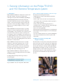
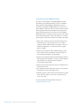
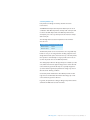
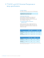
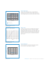
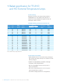
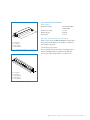
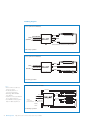
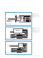
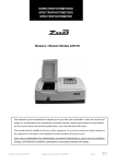
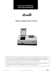
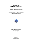
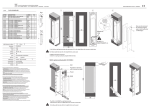
OEM Design Guide
Philips T5 VHO and HO Extreme Temperature Lamps and Ballasts
Content
3
1. General information on the Philips T5 VHO and HO Extreme Temperature system
3
1.1. Introduction
3
1.2. Optimum operation of T5 lamps with amalgam technology
4
2. Luminaire design
4
2.1. IEC Recommendations
4
2.2. Operating temperatures T5 VHO and HO Extreme Temperature lamps
5
2.3. General recommendations for handling and measuring T5 lamps and luminaires
5
2.4.Thermal luminaire design and ballast lifetime
6
2.5. Luminaire design and EMI performance
7
2.6. Lamp holder/cap
8
3.T5 VHO and HO Extreme Temperature lamp specifications
8
3.1. Product offerings
8
3.2. Mechanical characteristics
8
3.3.T5 VHO and HO Extreme Temperature publication values
10
4. Ballast specifications for T5 VHO and HO Extreme Temperature lamps
10
4.1. First start-up
10
4.2. Ballast ordering, electrical and technical data
10
4.3. Description of the ballast
10
4.4.Technical data for installation
10
4.5. Switching cycle effects
11
4.6. Wiring diagrams
1. General information on the Philips T5 VHO
and HO Extreme Temperature system
1.1. Introduction
Philips T5 VHO and HO Extreme Temperature are fluorescent
lamps with a diameter of about 0.63 in with the latest
technologies incorporated. These T5 VHO (Very High Output)
and HO (High Output) Extreme Temperature lamps have
temperature optimized performance and have a high lumen
output in a very broad temperature range (65–170°F). This
performance is achieved by adding an amalgam to the lamp.
Furthermore, two auxiliary amalgams are used for a faster
system run-up.
Philips T5 VHO Extreme Temperature lamps are especially
designed for mid-bay and high-bay applications with typical
mounting heights of 16 feet and above, such as factories, sports
arenas, train stations, warehouses, airports, and many more.
The advantages of fluorescent lighting in these applications are
good light distribution, beam control, instant hot restrike, long
life, dimmability and low maintenance costs.They are also well
suited for compact and indirect lighting fixtures where ambient
temperature is a critical element.
Philips T5 HO Extreme Temperature lamps are especially
designed for cold and warm applications, such as coolers,
outdoor luminaires, unconditioned warehouses, compact
luminaires (e.g. wall washers) or hot factory environments.
The lamps can be used in luminaires where currently the
same types with cold spot technology are used.
Philips T5 VHO and HO Extreme Temperature lamps are
designed for operation with high frequency electronic ballasts
for maximum efficacy.
Features of Philips T5 VHO and HO Extreme Temperature ranges
The lamps have the following characteristics:
• A high initial lumen output of approximately 7,200 lumens
for the VHO lamps
• A lumen output of more than 90% of the maximum lumen
output between 65°F and 170°F (lamp ambient temperature)
due to amalgam technology
• A fairly constant lumen level during lamp life due to a
tri-phosphor layer in combination with new coating technologies
• Narrow lamp diameter of about 0.63 inches
• Good color rendering (85 CRI)
• Rated average life of 25,000 burning hours at a 3 hr switching cycle
• Rated average life of 35,000 burning hours at a 12 hr switching cycle
• Low mercury
• To secure an optimal and hassle free operation, T5 VHO lamps
have a lamp cap with flattened pins which only fit into Gx5
lamp holders
1.2. Optimum operation of T5 lamps with
amalgam technology
The luminous flux of a low-pressure mercury lamp is determined
by the mercury vapor pressure in the lamp. In an amalgam lamp,
the mercury vapor pressure is determined by the amalgam itself
and not by the coldest spot in the lamp as with regular Philips T5
HE and HO lamps. An amalgam is an alloy of mercury and other
metal(s) and ensures a near-constant mercury pressure over a
wide temperature range. As a result of that, the lumen output is
more than 90% of the maximum lumen output between 65°F
and 170°F.
The Philips T5 Extreme Temperature range consists of
the following types:
T5 VHO 95W Extreme Temperature (46 in)
T5 HO 54W Extreme Temperature (46 in)
They are available in the color temperatures 835 and 841.
OEM Design Guide
Philips T5 VHO and HO Extreme Temperature Lamps and Ballasts
3
2. Luminaire design
2.1. International Electrotechnical Commission
(IEC) Recommendations
The general recommendations for luminaire design by IEC are also
applicable to T5 luminaires. Lamp-related data can be found in IEC
Standards 61195 for safety and 60081 for performance.
2.2. Operating temperatures T5 VHO and HO
Extreme Temperature lamps
2.2.1. Lamp temperatures
The data on the T5 lamps are based on free burning conditions in a
reference circuitry and the lamp should also be tested in that way,
unless stated otherwise.
2.2.2. Maximum temperatures of lamp parts
Luminaires for T5 lamps must satisfy the general requirements for
luminaires as specified by IEC 60598 and, if applicable, comply with
the requirements of local standards.The maximum allowed
temperature of the lamp cap is 248°F, as given in IEC 61195—
Double capped fluorescent lamps—Safety specifications.
2.2.3. Measuring the lamp cap for optimum lamp conditions
In comparison with cold spot mercury lamps, the relation between
light output and cap temperature is less direct with amalgam
lamps. Over a broad temperature range the light output is at a
very high level.
2.3. General recommendations for handling and
measuring T5 lamps and luminaires
2.3.1. Handling
Handling of T5 VHO and HO Extreme Temperature lamps is less
critical than the handling of T5 HE/HO lamps with cold-spot
technology. It is recommended to handle the lamps in a vertical
position with the stamp at the lowest side.
Allow the T5 Extreme Temperature VHO and HO lamps to cool
down for 10 minutes before handling.
4
OEM Design Guide
Philips T5 VHO and HO Extreme Temperature Lamps and Ballasts
2.3.2. Measuring luminaires for T5 lamps
Before measuring the light output ratio of a luminaire, the T5
Extreme Temperature lamps should be in a stable condition. The
following steps must be taken:
• To bring the lamps to a stable condition, operate the lamps for
approximately 100 hours
• Wait for 12 hours with the lamps turned off
• Measure the top lumen output of the lamps in the photometer
with a measurement time of approximately 15 minutes
• For measuring the total Phi-T curve, a temperature step of
1°F/hr must be applied, starting at a low temperature and going
to a high temperature
2.4.Thermal luminaire design and ballast lifetime
The ballasts for T5 VHO and T5 HO have a T_case max of 194°F
(90°C). To maximize the lifetime and to minimize the failure rate of
the ballast, the ballast should be placed inside the luminaire at a point
where the measured T_case is lowest.
The time after which 10% of the ballasts have failed is called
the constant failure rate. For a T5 VHO and HO ballast in normal
operation, this constant failure rate is approximately 50,000 hours
at a fixed specified case temperature (194°F). A temperature
increase of approximately 18°F halves this lifetime (thus, 212°F gives
25,000 hrs), while approximately 18°F lower doubles this figure
(176°F gives 100,000 hrs).
2.4.1.Thermal hints and tips
There is an increasing trend towards higher wattages and lumen
outputs in fluorescent lighting, leading to higher internal
temperatures of luminaires.
Every luminaire is different (difference in materials, dimensions,
applications, requirements, etc) so there is not just one simple
solution which helps to prevent overheating of the internal luminaire.
These hints and tips provide some ideas on how to deal with heat
management inside a luminaire.
In the case of T5 VHO, the minimum distance between the lamp
and the reflector must be at least 10mm. Adapting existing T5
luminaires (<54W) for T5 VHO requires more adjustment than
just changing the lamp holders and ballasts.
OEM Design Guide
Philips T5 VHO and HO Extreme Temperature Lamps and Ballasts
5
2.5. Luminaire design and EMI performance
The degree of electromagnetic compatibility (EMC) is basically
determined by the high frequency ballast concept in combination
with the luminaire design. Taking the following basic rules into
consideration will optimize the EMC behavior of the system and
help to fulfill the requirements. The basic rules are valid for both PL
and TL applications where functional and/or protective ground is
required. Functional ground can be required in order to fulfill the
EMC requirements or to guarantee proper operation of the system.
It means that an ignition aid or other metal surfaces are necessary,
which should be connected electrically to the housing of the ballast.
1. Ensure a firm electrical connection between the ballast and the
metal luminaire.The contact resistance has to be as small as
possible, so affix the ballast directly to the luminaire. The use of
additional mounting plates or several junctions has a negative
influence on EMC.
2. Keep the lamp wiring short. Avoid redundant wiring, e.g. loops.
The so-called ‘hot’ wires should be the shortest and have the
same (symmetrical) length for two lamp ballasts.
3. Keep the mains wiring far away from lamp wiring. Ensure that the
mains wiring inside the luminaire is as short as possible. Minimize
stray capacitance by ensuring that mains wiring does
not run parallel to lamp wiring.
4. Provide good electrical contact between the metal luminaire and
reflector and/or louver.
5. Use a shielding around the lamp, well connected to the luminaire.
This will help to reduce surrounding currents.
6. Minimize capacitance between wires and the luminaire. If possible,
mount the lamp wiring on spacers. Do not group wires by
means of tie wraps.
For more examples and background information visit:
www.advancetransformer.com
6
OEM Design Guide
Philips T5 VHO and HO Extreme Temperature Lamps and Ballasts
2.6. Lamp holder / cap
Lamp holders and wiring for T5 lamps should be the 500V
rated versions.
T5 VHO Extreme Temperature lamps have flattened pins for use in
combination with Gx5 lamp holders. T5 lamps with round pins will
not fit into the Gx5 lamp holders.The Gx5 lamp holders have a
small plastic part on the top which prevents the insertion of lamps
with round pins.
The following distances between lampholders in the luminaire
must be used:
T5 VHO 95W Extreme Temperature (46 in)
Minimum distance
45.24 in
Maximum distance
45.29 in
The Gx5 lamp holder can be mounted in the same way as G5 lamp
holders. In case you are using automatic checking equipment of the
wiring with automatic probes inserted in the top of the lamp holder,
this operation is unfortunately no longer possible as the holes are
used for the plastic insert of the Gx5 lamp holders.
The existing lamp holders for G5 capped lamps are suitable up to 250
volts, which means that the applied voltage must be lower than 250
volts towards the ground. As T5 lamps are especially designed for
operation with the high frequency ballasts the voltage may exceed
250 volts under dimming conditions.
Several lamp holder manufacturers have G5 lamp holders in their
range that are marked 500V, which means that voltages up to 500
volts towards the ground are allowed.
In general, all requirements relating to G5 type lamp holders will be
summarized in IEC 60061-2, 60061-4 and 400.
OEM Design Guide
Philips T5 VHO and HO Extreme Temperature Lamps and Ballasts
7
3. T5 VHO and HO Extreme Temperature
lamp specifications
3.1. Product offerings
The T5 Extreme Temperature range consists of the following types:
T5 VHO 95W Extreme Temperature (46 in)
T5 HO 54W Extreme Temperature (46 in)
3.2. Mechanical characteristics
The lamps fulfill the safety regulations found in IEC 61195 —
Double-capped fluorescent lamps—Safety specifications.
The nominal diameter of T5 lamps is 0.63 in; the maximum lamp
outline (including the bending) is 0.67 in.
3.3. T5 VHO and HO Extreme Temperature
publication values
T5 Extreme Temperature lamps are amalgam lamps with a very
broad temperature range. The lumen output is above 90% of the
maximum lumen output between 65°F and 170 °F. In table 3.1. the
nominal values are given.
Lamp type
Color
Lamp
Voltage
(V)
Discharge Resistance
Current
(A)
Lamp
power
(W)
Luminous
flux
(lm)
T5 VHO 95W
Extreme Temperature
835 / 841
123
800 mA
154
95
7200
T5 HO 54W
Extreme Temperature
835 / 841
118
460 mA
255
54
5000
Lamp type
Color
Lamp
Power
(W)
Luminous
flux
(lm)
Luminous
efficacy
(lm/W)
Luminance
cd/cm
T5 VHO 95W
Extreme Temperature
835 / 841
95
7200
76
4.4·104
T5 HO 54W
Extreme Temperature
835 / 841
54
5000
93
2.9·104
Table 3.1. Electrical and photometrical data of T5 VHO and HO Extreme Temperature lamps
Note: All data after 100 operating hours
8
OEM Design Guide
Philips T5 VHO and HO Extreme Temperature Lamps and Ballasts
Lumen output curves
In figure 3.1., the relative light output of a typical T5 Extreme
Temperature lamp in relation to the lamp ambient temperature is
shown. The light output is more than 90% between 65°F and 170°F.
Lumen output—T5 Extreme Temperature lamp
105
Relative Light Output (%)
100
95
90
85
80
75
70
65
60
0˚C
32˚F
10˚C
50˚F
20˚C
68˚F
30˚C
86˚F
40˚C
104˚F
50˚C
122˚F
60˚C
140˚F
70˚C
158˚F
80˚C
176˚F
Ambient Temperature ˚C
(˚F)
Standard F54 T5 HO Lamps
T5 Extreme Temperature Lamps
Figure 3.1. Relative light output of a T5 Extreme
Temperature lamp in relation to the lamp
ambient temperature
Run-up curves
In order to secure a fast run-up of the lamps, they are equipped
with auxiliary amalgams at both ends of the lamp. The auxiliary
amalgam increases the mercury vapor pressure after ignition of the
lamp. Within 3 minutes the lamp will reach 80% of its final output.
In figure 3.2. a typical run-up curve of a T5 Extreme Temperature
lamp is shown.
Run-up curve — T5 Extreme Temperature
Figure 3.2.Typical run-up curve of a T5
Extreme Temperature lamp
Lumen maintenance
The lumen maintenance of T5 Extreme Temperature lamps will
be at 90% at 40% of rated average life. See figure 3.3.
Lumen maintenance—T5 Extreme Temperature
100%
98%
Light Output (%)
96%
94%
92%
90%
88%
0
5,000
10,000
15,000
20,000
25,000
30,000
35,000
Lamp Operating Hours
Figure 3.3. Lumen maintenance of T5 Extreme
Temperature lamps
OEM Design Guide
Philips T5 VHO and HO Extreme Temperature Lamps and Ballasts
9
4. Ballast specification for T5 VHO
and HO Extreme Temperature lamps
4.1. First start-up
During the first start-up of the lamps, the lamps will have a
reddish/pinkish color in the middle of them. This effect is
related to the mercury distribution throughout the lamp and
will disappear within 2–3 minutes.
4.2. Ballast ordering, electrical and technical data
No. of
Lamps
T5 VHO
1
1
1
2
2
2
T5 HO
1
1
2
2
1
1
2
2
3
3
4
4
3
3
4
4
Input
Volts
Lamp
Starting
Method
Catalog
Number
Maximum
Input Power
Ballast
ANSI (Watts)
Factor
Line Current
(Amps)
Min.
Starting
Temp (˚F/˚C)
277
347
480
277
347
480
PS
PS
PS
PS
PS
PS
JOP-2S95-G
JOP-2S95-G
JOP-2S95-G
JOP-2S95-G
JOP-2S95-G
JOP-2S95-G
116W
116W
116W
206W
206W
206W
1.1
1.1
1.1
1.0
1.0
1.0
0.42
0.35
0.24
0.74
0.59
0.43
-19/-28
-19/-28
-19/-28
-19/-28
-19/-28
-19/-28
120
277
120
277
347
480
347
480
120
277
120
277
347
480
347
480
PS
PS
PS
PS
PS
PS
PS
PS
PS
PS
PS
PS
PS
PS
PS
PS
ICN2S5490CWL
ICN2S5490CWL
ICN2S5490CWL
ICN2S5490CWL
HCN2S5490CWL
HCN2S5490CWL
HCN2S5490CWL
HCN2S5490CWL
ICN4S5490C2LSG
ICN4S5490C2LSG
ICN4S5490C2LSG
ICN4S5490C2LSG
HCN4S5490C2LSG
HCN4S5490C2LSG
HCN4S5490C2LSG
HCN4S5490C2LSG
62W
62W
120W
117W
62W
62W
120W
119W
182W
179W
240W
234W
188W
186W
239W
237W
1.0
1.0
1.0
1.0
1.0
1.0
1.0
1.0
1.0
1.0
1.0
1.0
1.0
1.0
1.0
1.0
0.52
0.23
1.00
0.43
0.18
0.13
0.35
0.25
1.52
0.66
2.00
0.86
0.54
0.39
0.69
0.50
-20/-29
-20/-29
-20/-29
-20/-29
-20/-29
-20/-29
-20/-29
-20/-29
-20/-29
-20/-29
-20/-29
-20/-29
-20/-29
-20/-29
-20/-29
-20/-29
Above specifications subject to change without notice.
4.3. Description of the ballast
• Quick programmed start: 1.2 second warm start, preheating the
lamp electrodes; this enables the lamps to be switched on and off
without reducing life.
• Intellivolt® 120–277V, 347–480V, or 277–480V: constant light
independent of mains voltage fluctuations.
• End of Life Lamp (EOLL) protection: removes power to
lamps upon lamp failure.
• Auto-restart cicuitry: eliminates the need to reset power
mains after failed lamps are replaced.
• Low minimum starting temperature for cold applications.
10
OEM Design Guide
Philips T5 VHO and HO Extreme Temperature Lamps and Ballasts
4.4.Technical data for installation
Mains operation
Rated mains voltage
120–277V, 347–480V,
and 277–480V
Tolerances for safety:
+/– 10%
Mains frequency
50/60 Hz
Power factor
>= 0.99
A = 1.18" (30mm)
B = 1.70" (43.2mm)
C = 16.34" (415mm)
D = 16.70" (424.4mm)
Figure 4.1. T5 VHO and T5 HO 4 lamp case dimensions
DC voltage operation (during emergency back-up)
Because of the run up, T5 VHO and HO Extreme Temperature
lamps (and therefore ballast) are not suitable in combination
with emergency situations.
4.5. Switching cycle effects
The rated average lamp life of T5 lamps is negatively affected
when the switching frequency is higher than the IEC cycle
(3 hrs cycle: 2 hours and 45 minutes on, 15 minutes off).
A = 1.02" (26mm)
B = 1.18" (30mm)
C = 15.65" (397.5mm)
D = 16.34" (415mm)
E = 16.70" (424.2mm)
Figure 4.2. T5 HO 2 lamp case dimensions
OEM Design Guide
Philips T5 VHO and HO Extreme Temperature Lamps and Ballasts
11
4.6.Wiring diagrams
Advance JOP-2S95-G T5 VHO Ballast
LAMP
RED
(HOT)
BLACK/ORANGE
(NEUTRAL )
BLACK/WHITE
BALLAST
YELLOW
BLUE
Yellow leads must be connected for (1) lamp operation
One-lamp operation
Advance JOP-2S95-G T5 VHO Ballast
LAMP
RED
(HOT)
BLACK/ORANGE
(NEUTRAL )
BLACK/WHITE
BALLAST
YELLOW
BLUE
LAMP
Two-lamp operation
Notes:
• Green terminal or ballast case
must be grounded..
• Mount lamp within 1⁄4" of
grounded metal reflector.
• Max Voltage RED-YELLOW
leads 340Vrms.
• Install in accordance with National
and Local Electrical Codes.
• Use 18AWG Solid Copper Wire
Rated >=600V. Strip Wire 3⁄8".
Advance ICN4S5490C2LSG T5 VHO Ballast
ORANGE
WHITE
Neutral
or (any hot)
BROWN
YELLOW
S
GREY/RED
250V,
1mA
Four-lamp operation
12
OEM Design Guide
RED
BLUE
BLACK
Philips T5 VHO and HO Extreme Temperature Lamps and Ballasts
BLUE/WHITE
Advance HCN4S5490C2LSG T5 VHO Ballast
ORANGE
LAMP
(Hot)
(Neutral)
RED
BLUE
BLACK WITH ORANGE STRIPES
BLACK WITH WHITE STRIPES
LAMP
BROWN
YELLOW
GREY/RED
S
Neutral or (any Hot)
250V,
1mA
Notes:
• Max.Voltage RED-YELLOW
Leads 340Vrms.
• Insulate unused leads for 600V.
• Ballast case must be grounded.
• Mount lamps within 1⁄4" of grounded
metal reflector.
LAMP
LAMP
BLUE/WHITE
Four-lamp operation
Advance ICN2S5490CWL T5 VHO Ballast
BLACK
WHITE
BALLAST
RED
RED
YELLOW
YELLOW
BLUE
BLUE
Notes:
• Ballast case must be grounded.
• Mount lamps within 1⁄4" of grounded
metal reflector.
• Install in accordance with National and
Local Electrical Codes.
• Use 18AWG Solid Copper Wire
Rated >=600V. Strip Wire 3⁄8".
LAMP
LAMP
Two-lamp operation
Advance HCN2S5490CWL T5 VHO Ballast
RED
RED
(Hot)
(Neutral)
BLACK WITH ORANGE STRIPES
BLACK WITH WHITE STRIPES
BALLAST
YELLOW
YELLOW
BLUE
BLUE
LAMP
LAMP
Two-lamp operation
OEM Design Guide
Philips T5 VHO and HO Extreme Temperature Lamps and Ballasts
13
Philips Lighting Company
200 Franklin Square Drive
P.O. Box 6800
Somerset, NJ 08875-6800
1-800-555-0050
A Division of Philips Electronics North America Corporation
Philips Lighting
281 Hillmount Road
Markham, Ontario
Canada L6C 2S3
1-800-555-0050
A Division of Philips Electronics Ltd.
www.philips.com
10275 West Higgins Road
Rosemont, IL 60018-5603
1-800-322-2086
A Division of Philips Electronics North America Corporation
www.advancetransformer.com
©2008 Philips Lighting Company, A Division of Philips Electronics North America Corporation
All rights reserved. Reproduction in whole or part is prohibited without the prior written consent of the copyright owner.The information
presented in this document does not form part of any quotation or contract, is believed to be accurate and reliable and may be changed
without notice. No liability will be accepted by the publisher for any consequence of its use. Publication thereof does not convey nor imply any
license under patent or other industrial or intellectual property rights.This guide is for OEM use only. Data subject to change without notice.
6/08
P-5920