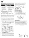
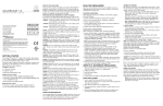
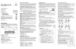
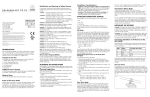
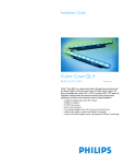
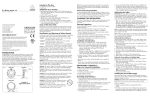
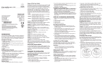
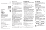
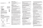
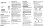
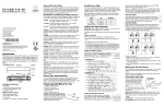
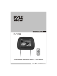
1
colorbl a z e 72
Color Kinetics® ColorBlaze® 72 is designed for washing large areas with far-reaching, rich, saturated colors and color changing effects. The streamlined, six-foot fixture is a simple yet powerful solution
for large-area scenery and wash lighting for venues such as theaters, TV studios, concerts, events, casinos, and exhibits. On-board power supplies and addressing capabilities eliminate the need for special
equipment, simplifying specification and installation, and its auto-switching power supplies are suited
for both domestic and international use.
Designed in a rugged extruded aluminum housing, each fixture features attached mounting brackets,
each with three, 1/2-inch (1.3 cm) mounting holes for use with Cheeseborough clamps or pipe
clamps. Locking knobs located on the mounting brackets allow for 180° rotational adjustment and
locking without the use of special tools. Optional ColorBlaze mounting bracket are available for
T-handle mount applications. The housing is equipped to affix spread lenses, louvers, and other
attachments. A single 3-wire, 18AWG 6-foot (1.8 m) UL/cUL rated cord with IEC and flying leads is
supplied. (Consult distribution for cord sets listed for PSE or CE).
Each ColorBlaze 72 has 12 individual circuit board assemblies with 18 high-intensity LEDs per board,
making it sequentially controllable in 6-inch increments by a Color Kinetics DMX controller or a thirdparty DMX512 controller. Each circuit board is pre-addressed for Light# 1-12/DMX# 1-36. Data can
be daisy-chained from fixture to fixture with an RJ45 data cable or an XLR-5 data cable.
For protection from overheating, ColorBlaze 72 has been designed with a temperature monitoring
feature. If operating temperatures rise to an unsafe level, a compensation circuit is triggered and
ColorBlaze 72 operation is interrupted causing the lights to turn dull red. After 30 minutes the lights
will auto-cycle and return to full intensity.
colorblaze 72 specifications
color range
source
beam angle
housing
power connector
data connectors
listings
16.7 million (24 bit) additive RGB colors; continuously variable intensity
output range
High intensity light emitting diodes (LEDs)
10°
Extruded aluminum with black finish
IEC 15A (max) with C13 plug, UL/cUL rated
2-pole, 3-wire, grounded, 15A, flying leads
RJ45 or XLR-5
UL/cUL, CE, PSE
CO M M U NICATION s p e c i f i c a t i o n s
DMX512
Color Kinetics full line of DMX controllers or other DMX512 (RS485) controllers
data interface
control
ELECTRICAL s p e c i f i c a t i o n s
voltage requirement
power consumption
100-240VAC
420W, 3.7A nominal at full intensity (full RGB)
Environmental Specifications
temperature range
DRY
ITEM# 116-000015-00
This product is protected by one or more of the following patents:
U.S. Patent Nos. 6,016,038, 6,150,774 and other patents listed at
http://colorkinetics.com/patents/. Other patents pending.
©2003-2006 Color Kinetics Incorporated. All rights reserved.
Chromacore, Chromasic, Color Kinetics, the Color Kinetics
logo, ColorBlast, ColorBlaze, ColorBurst, ColorCast, ColorPlay,
ColorScape, Direct Light, iColor, iColor Cove, iPlayer, Optibin,
Powercore, QuickPlay, Sauce, the Sauce logo, and Smartjuice are
registered trademarks and DIMand, IntelliWhite, Video With Light,
and Light Without Limits are trademarks of
Color Kinetics Incorporated.
All other brand or product names are trademarks
or registered trademarks of their respective owners.
BR0113 Rev 06
Specifications subject to change without notice. Refer to
www.colorkinetics.com for the most recent data sheet versions.
-40°F to 122°F (-40°C to 50°C) operating temperature
14°F to 122°F (-10°C to 50°C) starting temperature
LED source life
In traditional lamp sources, lifetime is defined as the point at which 50% of the lamps fail. This is also termed Mean
Time Between Failure [MTBF]. LEDs are semiconductor devices and have a much longer MTBF than conventional
sources. However, MTBF is not the only consideration in determining useful life. Color Kinetics uses the concept of useful light output for rating source lifetimes. Like traditional sources, LED output degrades over time (lumen depreciation)
and this is the metric for SSL lifetime.
LED lumen depreciation is affected by numerous environmental conditions such as ambient temperature, humidity and
ventilation. Lumen depreciation is also affected by means of control, thermal management, current levels, and a host
of other electrical design considerations. Color Kinetics systems are expertly engineered to optimize LED life when
used under normal operating conditions. Lumen depreciation information is based on LED manufacturers’ source life
data as well as other third party testing. Low temperatures and controlled effects have a beneficial effect on lumen
depreciation. Overall system lifetime could vary substantially based on usage and the environment in which the system
is installed.
Temperature and effects will affect lifetime. Color Kinetics rates product lifetime using lumen depreciation to 50% of
original light output. When the fixture is running at room temperature using a color wash effect, the range of lifetime is
in the range of 80,000-100,000 hours. This is LED manufacturers’ test data. High output is defined as any LED device
that is 1/2 watt or above. For more detailed information on source life, please see www.colorkinetics.com/lifetime.
Optibin®
There are inherent variations in the fabrication processes of all semiconductor materials. For LEDs, this variance results
in differences in the color and intensity of light output as well as electrical characteristics. Due to these differences, LED
manufacturers sort production into “bins,” but insuring the availability of a single bin is very difficult. To minimize this
issue and achieve optimal color consistency in its products, Color Kinetics has developed and uses a proprietary technology called Optibin. Optibin is an advanced production binning optimization process that minimizes the effects of
LED variance for the best possible output uniformity in the final product. Color Kinetics Optibin technology gives you
the most consistent control of color and intensity from product to product.
Philips Solid-State Lighting Solutions • 3 Burlington Woods Drive • Burlington, MA 01803 • USA
Tel 888 FULL RGB • Tel 617 423 9999 • Fax 617 423 9998 • [email protected] • www.colorkinetics.com
colorblaze 72
photometric performance
Photometric data is based on test results from an independent testing lab.
source specifications
Optics: Clear polycarbonate
Source:
216 LEDs (72 Red, 72 Green, 72 Blue)
Beam Angle:
10° (at 50% of peak illuminance)
Distribution:
Symmetric direct illumination
CCT:
Adjustable 1,000 – 10,000K
CRI:
Not measurable (CIE 13.3-1995)
illuminance distribution
13.4
15.9
144.2
36.7
328.3
105.0
78.2
1324.0
128.0
25.3
39.0
272.3
2185.1
1463.9
419.8
42.7
3.0’/1.0m
3.0’/1.0m
-90
1507.0
1205.6
white
3’
1m
1693.0
18223.5
569.4
6128.5
826.2
blue
White
56898 cd
Indicates 50% of peak
0.34 Red, 0.49 Green, 0.18 Blue
90
56898
446.7
374.6
0.0’/0.0m
3.0’/1.0m
Footcandles (top)/Lux (bottom)
10.8 lux = 1 fc
All, reflectance model 80/50/20%
Bottom of grid, 3’ (1.0 m) from
surface, light at a 45º angle off horizontal
6’
green
42674
light output
red
28449
34.8
Illuminance
color
14225
Measured on:
Beam center:
Thin dashed line:
Multipliers:
112.0
41.5
459.6
765.3
140.0
1420.8
0’/0m
Units:
Measured on:
Distance from surface:
71.1
2099.0
132.0
1453.1
458.5
248.6
1280.9
195.0
135.0
42.6
369.2
1367.0
2174.3
23.1
119.0
203.0
136.0
1377.8
410.1
1356.3
130.2
34.3
127.0
202.0
2099.0
841.7
413.3
0
6.0’/2.0m
12.1
162.5
38.1
126.0
195.0
15.1
174.4
38.4
123.0
1539.3
16.2
176.5
395.0
1130.2
143.0
16.4
171.1
30.5
candle power distribution
8893.0
308.1
3316.7
9’
15’
2m
626.0
6738.3
210.5
2266.1
305.5
3288.3
113.9
1226.4
3m
247.0
2658.7
83.1
894.1
120.5
1297.4
45.0
483.9
5m
135.0
1453.1
45.4
488.7
65.9
709.1
total output
power
efficacy
(lumens)
(Watts)
(Lm/w)
3532
382.0
9.2
red
1187.8
166.0
7.2
green
1723.6
166.0
10.4
642.8
166.0
3.9
color
white
blue
24.6
264.5
Measured in Footcandles (top)/Lux (bottom) on axis.
Measured on: All, reflectance 0.
Philips Solid-State Lighting Solutions • 3 Burlington Woods Drive • Burlington, MA 01803 • USA
Tel 888 FULL RGB • Tel 617 423 9999 • Fax 617 423 9998 • [email protected] • www.colorkinetics.com
colorblaze 72
physical dimensions
A
B
5
1
4
2
3
5
1
4
2
3
68.583"
7.73”
(19.6 cm)
5.10”
(13.9 cm)
A
TOGGLE SWITCH
Set light address
8.97”
(22.7 cm)
7.54”
(19.2 cm)
4.79”
(12.2 cm)
3.31”
(8.4 cm)
DISPLAY
Light address
DMX DATA IN
RJ45 OR XLR-5
ACCESSORY
POWER JACK
5
1
OPTIONAL MOUNTING BRACKET
4
2
3
FOR T-HANDLE MOUNING
5
1
4
2
3
DATA
INDICATOR
TEST BUTTON
DMX DATA OUT
RJ45 OR XLR-5
DISPLAY
Number of addresses per fixture
9.1"
(23.2 cm)
B
TOGGLE SWITCH
Set number of addresses
per fixture.
0.20"
(0.5 cm)
R0.25"
(0.6 cm)
1.06"
(2.7 cm)
4"
(10.2 cm)
1.18"
(3.0 cm)
1.18"
(3.0 cm)
7.5"
(19.2 cm)
6.6"
(16.7 cm)
1.18"
1.20"
(3.0 cm) (3.0 cm)
COLORBLAZE 72
item# 116-000015-00/01
weight (approx)
60 lb (27 kg)
power cable
IEC 15A (max) with C13 plug
power requirement
100-240VAC (420W)
Philips Solid-State Lighting Solutions • 3 Burlington Woods Drive • Burlington, MA 01803 • USA
Tel 888 FULL RGB • Tel 617 423 9999 • Fax 617 423 9998 • [email protected] • www.colorkinetics.com
colorblaze 72
functional flow diagram
AC POWER CONNECTION
IEC 15A (MAX) C13 PLUG
100-240VAC
AND
2 POLE, 3 WIRE GROUNDED
15A PLUG (NOT INCLUDED)
5
1
5
1
4
2
4
2
3
3
DATA CABLE
FROM CONTROLLER
TO DATA IN
XLR-5 DATA CONNECTION
5
1
SHIELD
DATA DATA +
N.C.
N.C.
5
1
4
2
DMX
DATA IN
DMX
DATA OUT
5
1
5
1
4
2
4
2
3
3
DATA CABLE
FROM DATA OUT
TO DATA IN
ON NEXT FIXTURE
3
3
4
2
3
PIN 1
PIN 2
PIN 3
PIN 4
PIN 5
5
1
4
2
CONTINUE DMX OUT/IN
SEQUENCE TO INCLUDE ALL
FIXTURES IN CHAIN, THEN
TERMINATE THE LAST.
(SEE NOTES)
DMX
DATA OUT
XLR-5
DMX
DATA IN
5
1
5
1
4
2
4
2
3
3
DMX
DATA IN
DMX
DATA OUT
5
1
DATA CABLE
DETAIL A
3
AC POWER CONNECTION
IEC 15A (MAX) C13 PLUG
100-240VAC
AND
2 POLE, 3 WIRE GROUNDED
15A PLUG (NOT INCLUDED)
5
1
4
2
3
4
2
3
4
2
3
DETAIL C
(SEE NOTES)
RJ45 DATA CONNECTION
1 2 34 56 78
5
1
5
1
DATA CABLE
FROM CONTROLLER
TO DATA IN
PIN 1 DATA PIN 2 DATA +
PIN 3 SHIELD
4
2
5
1
4
2
3
DMX
DATA OUT
DMX
DATA IN
5
1
4
2
3
RJ45 8-PIN
(VIEW FACING PINS)
DATA CABLE
FROM DATA OUT
TO DATA IN
ON NEXT FIXTURE
5
1
4
2
3
5
1
4
2
3
CONTINUE DMX OUT/IN
SEQUENCE TO INCLUDE ALL
FIXTURES IN CHAIN, THEN
TERMINATE THE LAST.
(SEE NOTES)
NOTES:
DATA CABLE
(CAT-5 UTP 24AWG 4 PAIR)
DETAIL B
For complete installation instructions and safety
precautions, refer to the ColorBlaze 48/72
User Guide and wiring diagrams located at
www.colorkinetics.com/support.
1. PLACE TERMINATOR IN DMX DATA OUT PORT OF THE LAST FIXTURE IN A CHAIN.
2. MAXIMUM DMX DATA RUN FROM DMX SOURCE TO LAST FIXTURE IN CHAIN IS 1000 FEET (O R 300 m).
3. DMX DATA CHAINS NEED NOT BE CONNECTOR SPECIFIC, FOR EXAMPLE: XLR-5 INPUT WITH RJ45
OUTPUT AND VICE VERSA. SEE DETAIL C.
4. THE ACCESSORY POWER JACK IS FOR USE WITH COLOR KINETICS PRODUCTS ONLY.
Additional Items
Power Plug
2 Pole, 3 Wire, Grounded, 15A Power Plug
Controller
Color Kinetics DMX controller or DMX512 compatible controller
Data Cables
RJ45 or XLR-5 data cables
Philips Solid-State Lighting Solutions • 3 Burlington Woods Drive • Burlington, MA 01803 • USA
Tel 888 FULL RGB • Tel 617 423 9999 • Fax 617 423 9998 • [email protected] • www.colorkinetics.com