1
R
T E
C H
N O L O G Y
Custom Installation Series
Owners Manual / Installation Instructions
Power FL-8
CI-1.5
Power FL-10
Power FL-12
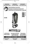
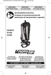
Speaker seismic
restraint hole
SpeedWing™ mounting arms
Baffle
Installation aid/paint mask
Grille safety clip
Grille
Box contents
1
1
1
1
1
Speaker
Grille
Paint mask
Hole template
Euroblock connector
MSE Audio Group
8650 College Boulevard Overland Park, Kansas 66210
www.mseaudio.com www.phasetech.com
(866) 663-9770
Installation Instructions: Installing the
CI-1.5 in a Sheetrock Ceiling
R
T E
C H
N O L O G Y
1. Unpack speaker. Leave
paint mask in place until
after speaker is installed or
painting is complete.
5. If required, attach seismic
restraint system to hole in
clamping arm, then to
reinforced structure (safety
cable not included).
2. Use hole template to
mark cutout on sheetrock.
3. Use RotoZip or other tool
to cut hole. Hole diameter:
5.6 in. (142 mm).
6. Insert speaker into
mounting hole with paint
mask in place. Tighten both
screws on the baffle face to
actuate the mounting wings.
Firmly secure both screws,
DO NOT OVERTIGHTEN.
7. Remove paint mask
unless painting is required.
In that case, follow steps
8-11 when painting is
complete.
1.
2.
9. Attach grille safety clip by
placing the large end of the
clip over snap-fit post (1),
then sliding clip until small
end snaps into place around
post (2).
10. Align tabs on snap-fit
grille with slots in baffle,
gently press grille into place.
11. Done!
4. Connect Euroblock to
speaker wires, and connect
to speakers.
8. Adjust tap switch to
proper setting. Switch is
preset to 8-ohm mode.
R
T E
C H
N O L O G Y
Installation Instructions: Installing the CI-1.5
Using Optional Pre-Construction Bracket
1. Nail or screw bracket to
joists.
2. Finish installing ceiling.
3. Use RotoZip or other tool
to cut hole.
4. Unpack speaker. Leave
paint mask in place until
after speaker is installed or
painting is complete.
5. Connect euroblock to
speaker wires, and connect
to speakers.
6. If required, attach
seismic restraint system to
the sheet-metal tab on the
rear panel of the speaker,
then to reinforced structure
(safety cable not included).
7. Insert speaker into
mounting hole. Tighten both
screws on the baffle face to
actuate the mounting wings.
DO NOT OVERTIGHTEN.
8. Remove paint mask
unless painting is required.
In that case, follow steps
9-12 when painting is
complete.
1.
2.
9. Adjust tap switch to
proper setting. Switch is
preset to the 8-ohm mode.
11. Align tabs on snap-fit
10. Attach grille safety clip
grille with slots in baffle,
by placing the large end of
the clip over snap-fit post (1), gently press grille into place.
then sliding clip until small
end snaps into place around
post (2).
12. Done!