1
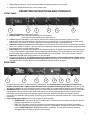
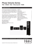
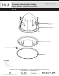
P-200
HIGH CURRENT
MULTI-APPLICATION
SUBWOOFER/MONO-BLOCK
POWER AMPLIFIER
USER’S GUIDE
SAFETY INSTRUCTIONS
CAUTION: To reduce the risk of electric shock, do not
remove cover (or back). No user-serviceable parts
inside. Refer servicing to qualified service personnel.
• Explanation of Graphical Symbols
The lightning flash with arrowhead symbol,
within an equilateral triangle, is intended to
alert you to the presence of un-insulated
“ dangerous voltage” within the product’s
enclosure that may be of sufficient magnitude
to constitute a risk of electric shock to
persons.
The exclamation point within an equilateral
triangle is intended to alert you to the
presence of important operating and maintenance
(servicing) instructions in
the literature accompanying the appliance.
1. Read Instructions - All the safety and operating
instructions should be read before the appliance is
operated.
2. Retain Instructions - The safety and operating
instructions should be retained for future reference.
3. Heed Warnings - All warnings on the appliance and
in the operating instructions should be adhered to.
4. Follow Instructions - All operating and other
instructions should be followed.
5. Water and Moisture - The appliance should not be
used near water - for example, near a bathtub,
washbowl, kitchen sink, laundry tub, in a wet
basement, or near a swimming pool, etc.
6. Carts and Stands - The appliance should be used
only with a cart or stand that is recommended by the
manufacturer.
PORTABLE CART
WARNING
such as a bookcase or cabinet that may impede the
flow of air through the ventilation openings.
9. Heat - The appliance should be situated away from
heat sources such as radiators, stoves, or other
appliances that produce heat.
10. Power Source - The appliance should be connected
to a power supply only of the type described in the
operating instructions or as marked on the appliance.
11. Power-Cord Protection - Power-supply cords should
be routed so that they are not likely to be walked on
or pinched by items placed upon or against them,
paying particular attention
to cords at plugs, convenience receptacles, and the
point where they exit from the appliance.
12. Cleaning - The appliance should be cleaned only
as recommended by the manufacturer.
13. Nonuse Periods - The power cord of the appliance
should be unplugged from the outlet when left unused
for a long period of time.
14. Object and Liquid Entry - Care should be taken so
that objects do not fall into and liquids not spilled
into the inside of the appliance.
15. Damage Requiring Service - The appliance should
be serviced by qualified service personnel when:
a. The power-supply cord or the plug has been
damaged; or
b. Objects have fallen onto, or liquid has been
spilled into the appliance; or
c. The appliance has been exposed to rain; or
d. The appliance does not appear to operate normally
or exhibits a marked change in performance; or
e. The appliance has been dropped, or the cabinet
damaged.
16. Servicing - The user should not attempt to
service the appliance beyond those means described in
the operating instructions.
All other servicing should be referred to qualified
service personnel.
17. Grounding or Polarization - The precautions that
should be taken so that the grounding or polarization
means of an appliance is not defeated.
APPLICABLE FOR USA, CANADA OR WHERE
APPROVED FOR USAGE
7. Wall or Ceiling Mounting - The appliance should be
mounted to a wall or ceiling only as recommended by
the manufacturer.
8. Ventilation - The appliance should be situated so
that its location or position does not interfere with
its proper ventilation. For example, the appliance
should not be situated on a bed, sofa, rug, or
similar surface that may block the ventilation
openings; or placed in a built-in installation,
CAUTION: TO PREVENT ELECTRIC SHOCK, MATCH
WIDE BLADE PLUG TO WIDE SLOT, INSERT FULLY.
ATTENTION: POUR EVITER LES CHOCS ELECTRIQUES,
INTRODUIRE LA LAME LA PLUS LARGE DE
LA FICHE DANS LA BORNE CORRESPONDANTE DE
LA PRISE ET POUSSER JUSQU AU FOND.
INTRODUCTION
Thank you for your purchase of the Phase Technology P200 amplifier. This versatile amplifier is designed to provide years of
reliable service and listening pleasure. The P200 is the companion amplifier to the Phase Technology IW-100 and IW-200 inwall subwoofer systems but its use is not limited to only subwoofer applications. The P200 also provides you with the
flexibility of operation as a full range high current, high performance, mono-block audio power amplifier.
As a subwoofer amplifier the P200 incorporates many features that provide operational and installation flexibility.
• Variable input level control
• Variable low pass crossover at 24 dB/octave
• Phase control
• Variable low frequency equalization for room placement optimization
• Switchable input circuitry for Subwoofer, LFE or Full Range applications
• Auto-signal sensing for automatic amplifier turn on
• 12V auto turn-on for use with home remote control applications
• High current/high capacity power supply
2
•
•
Rugged design that fits in a single rack space with thermostatically controlled cooling fan
Designed to operate efficiently into 4 ohm speaker loads
OPERATING INSTRUCTIONS AND CONTROLS
FRONT PANEL
1
2
3
4
5
6
1. Power on-off switch, master power control
2. Indicator LEDs: Power LED, red indicator light for main power on
Dual color LED: Red Standby-mute, Green Auto-on
3. Volume input level adjustment. This control is used for level matching of the subwoofer system to the main
loudspeakers. We recommend that you start with this control in about the 9-10 o’clock position as an initial setting
and use the level controls on the main equipment for fine adjustment of the overall speaker level.
4. Subwoofer low-pass crossover control adjustable is from 40-160 Hz. This control is active only with the rear panel
switch in the subwoofer position. This control should be adjusted to obtain the smoothest transition in sound between
the subwoofer and your main speaker system.
5. Phase switch is for amplifier output phase control. Outward position is 0º amplifier signal phase and inward position
is 180º inverted amplifier signal phase. Please experiment with this setting. The correct setting is that which yields
the fullest bass and smoothest blend of the subwoofer with your main speakers. This control is active in both the
Subwoofer and LFE switch setting positions on the rear panel.
6. Ventilation air intake grille. It is important that for the proper operation of this amplifier that this intake remain
unobstructed both in the installation and during operation. Blocking this air vent will cause the amplifier to over
heat and shut down. If proper airflow is not maintained the amplifier could be damaged.
REAR PANEL
1
2
3
4
5
6
7
8
1. Ventilation exhaust grille is for thermostatically controlled fan. It is important that for the proper operation of this
amplifier that this intake remain unobstructed both in the installation and during operation. Blocking this air vent
will cause the amplifier to over heat and shut down. If proper airflow is not maintained the amplifier could be damaged.
2. SPEAKER OUTPUT connection terminals are of the 5-way binding post design, which accepts banana, pin or bare wire
type of speaker cable connections. We recommend that you use at least 14-gauge speaker wire for these hookup
connections. The black terminal is the speaker negative connection and the red terminal is the speaker positive
connection. For installation with the Phase Technology IW-100 and IW-200 subwoofers please refer to their installation
instructions.
3. Input selector mode switch sets the mode of operation of the amplifier.
• SUBWOOFER: This position allows the amplifier to be used as a full function subwoofer amplifier. All of the
features of the amplifier are operational.
• LFE: The LFE position is used for connection to home theater equipment with a separate controllable
subwoofer output that has its own crossover frequency compensation. This feature is found on most of the
current DOLBY DIGITAL® and DTS® home theater equipment. The front panel Crossover control is
disengaged when the selector switch is in this position.
3
•
4.
5.
6.
7.
8.
9.
FULL RANGE: This switch position transforms the P200 amplifier in to a high performance 20Hz-20kHz,
200-watt mono-block power amplifier. With the switch in this position the front panel Crossover control and
the rear panel Low Frequency Equalization control do not function.
LINE IN connectors are a set of dual RCA type plugs that accept an input signal from the subwoofer or main signal
outputs from your home theater receiver or control center. Either one or both of the inputs can be used as required. The
left and right input signals are summed together in the amplifier to provide it with a mono input signal.
LOW FREQUENCY EQ control adjusts the bass contour of the amplifier and subwoofer to allow the optimization of the
subwoofer performance compensating for variations in room acoustics and installation locations. This control provides an
adjustment range of –3dB to +6 dB centered around 30 Hz.
TRIGGER INPUT is provided for remote control switching of the auto-on circuit of the P200 amplifier. A positive 12V
trigger signal applied to the tip of a 3.5mm mini plug inserted into this connector activates the amplifier. When the voltage
drops to 0 the amplifier will turn off. This input overrides the automatic music sensing circuit in the amplifier. The
automatic music sensor activates when it senses that an audio signal is present at the LINE IN connectors and after 3-4
seconds turns on the amplifier. When the input signal is removed the amplifier will go turn off after about 10 minuets.
A/C power line voltage selector is used to properly matching the line voltage of your wall outlet to the P200 amplifier.
For the USA and Canada this switch is set to the 110-120V position. For other countries the customer should check with
his retailer for the proper setting and line cord requirements.
The power line cord socket is for the connection of the main power cord from your wall outlet to the amplifier. In the
USA and Canada the amplifier is supplied with a standard IEC polarized power cord.
The power socket also contains the main power fuse for the P200 amplifier. Should the amplifier fail to operate unplug
the amplifier from the wall outlet and remove the power cord from the rear of the amplifier. Remove the fuse cover
located under the power cord socket by prying up on it with a small screwdriver and check the main power fuse. If the
fuse is blown there is a spare fuse in the cover that can be used to replace the blown fuse. Replace the main power
fuse with only the size and current specified on the rear of the amplifier per you’re A/C input voltage
requirements.
SPECIFICATIONS
AMPLIFIER POWER
CROSSOVER FREQUENCY
LFE FREQUENCY
RESPONSE
FULL RANGE RESPONSE
INPUT SENSITIVITY
LOW FREQUENCY EQ
DIMENSIONS
WEIGHT
200 WATTS CONTINUOUS LESS THEN .1% THD @ 4 OHMS, 350 WATTS PEAK
150 WATTS CONTINUOUS LESS THEN .1% THD @ 8 OHMS, 215 WATTS PEAK
40-160 HZ ADJUSTABLE @ 24 DB/OCTAVE LOW PASS
20-500 Hz
10Hz-40kHz + 1 dB
150 mV FOR FULL OUTPUT
-3dB to +6dB @ 30 Hz
17.75”W x 1.875”H x 11.75”D
18 LBS
Limited Warranty
Phase Technology warrants its loudspeakers to be free from defects in material and workmanship for a period of ten (10) years for speaker
product and three (3) years for the electronic components to the original purchaser. Purchase must be made from an authorized Phase
Technology dealer.
This warranty does not cover service or parts to repair damage caused by misuse, abuse, damage while in transit, alterations,
unauthorized repairs, failure to follow instructions, fire, flood or any other cause beyond the reasonable control of Phase Technology.
Defects in speaker cabinets or grilles must be brought to the attention of your dealer immediately after purchase. This warranty will be void
if the products’ serial number has been altered or removed.
To obtain warranty service, defective product must be shipped in its original carton or equivalent together with original invoice or bill of sale,
insured and prepaid to your authorized Phase Technology dealer or the factory when warranty service is requested.
If you choose to return the defective product to the factory you must first call us at (904) 777-0700 to obtain a Return Authorization number
prior to shipping. Product repaired under this warranty will be returned to you freight collect.
Implied Warranties
Phase Technology will not pay for loss of time, inconvenience, loss of use, or property damage caused by your speaker product or its
failure to work, or any other incidental or consequential damages. Some states do not allow the exclusion or limitation of consequential
damages, so the above limitation may not apply to you.
PHASE TECHNOLOGY CORPORATION
6400 YOUNGERMAN CIRCLE
JACKSONVILLE, FL 32244
1-888-PHASETK
www.phasetech.com
4
218-2029