1
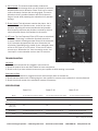
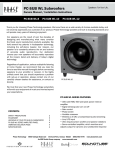
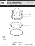
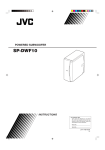
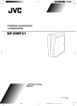
Power FL Subwoofers
T E
C H
N O L O G Y
Owners Manual / Installation Instructions
Power FL-8
Power
FL-10 Power FL-12
FL-8
FL-10
FL-12
Thank you for selecting Phase Technology speakers. We know there are a wide variety of choices available today, and
we sincerely appreciate your purchase of our product. Phase Technology speakers are built to exacting standards and
will provide many years of listening enjoyment.
Our speakers are the result of over five decades of
designing and manufacturing what many consider
the finest sound reproduction products available. We
hold several key patents in loudspeaker technology
including the soft-dome tweeter. Our mission, our
passion is to constantly advance the art and science
of accurate audio reproduction. Our dedication
insures your new speakers will accurately reproduce
all the impact, detail and delicacy of today’s digital
technology.
Regardless of application, serious audiophile
listening or home theater, we recommend that you
take the time to read this manual thoroughly before
connecting speakers to your amplifier or receiver. In
the highly unlikely event that you should experience
a problem with set-up or operation, please contact
one of our carefully chosen dealers for assistance, or
contact us directly.
We trust that your new Phase Technology speakers
will enrich your enjoyment of music and movies
beyond your expectations.
Power FL-10
POWER FL SERIES FEATURES:
CONTENTS:
POWER FL SERIES FEATURES
SAFETY PRECAUTIONS
PLACEMENT
HOOKING UP YOUR POWER FL SUBWOOFER
POWER FL SERIES AMPLIFIER PANEL
SPECIFICATIONS
Phase Technology Corporation
1
2
3
3
3
4
6400 Youngerman Circle
250 watt amplifier
Signal sensing auto turn on/off
Gain control
Phase switch
Variable crossover
Line/level inputs
LFE input
Oversized surround for ultra long excursion
Servo-control, which monitors and adjusts output for
dynamic and undistorted response
Jacksonville, Florida 32244
1.888.PHASE TK
www.phasetech.com
SAFETY INSTRUCTIONS
CAUTION
RISK OF ELECTRIC SHOCK
DO NOT OPEN
!
CAUTION: To reduce the risk of electric shock, do not remove cover (or
back). No user-serviceable parts inside. Refer servicing to qualified service
personnel.
Explanation of Graphical Symbols
The lightning flash with arrowhead symbol, within an
equilateral triangle, is intended to alert you to the
presence of un-insulated “dangerous voltage: within the
product’s enclosure that may be off sufficient magnitude
to constitute a risk of electric shock to persons.
!
The exclamation point within an equilateral triangle
is intended to alert you to the presence of important
operating and maintenance (servicing) instructions in the
literature accompanying the appliance.
1. Read Instructions - All the safety and operating
instructions should be read before the appliance is
operated.
2. Retain Instructions - The safety and operating
instructions should be retained for future reference.
3. Heed Warnings - All warnings on the appliance and in
the operating instructions should be adhered to.
4. Follow Instructions - All operating and other
instructions should be followed.
5. Water and Moisture - The appliance should not be
used near water - for example, near a bathtub, washbowl,
kitchen sink, laundry tub, in a wet basement, or near a
swimming pool, etc.
6. Carts and Stands - The appliance should be used
only with a cart or stand that is recommended by the
manufacturer.
PORTABLE CART WARNING
7. Wall or Ceiling Mounting - The appliance should be
mounted to a wall or ceiling only as recommended by the
manufacturer.
8. Ventilation - The appliance should be situated so that
its location or position does not interfere with its proper
ventilation. For example, the appliance should not be
situated on a bed, sofa, rug, or similar surface that may
block the ventilation openings; or placed in a built-in
installation, such as a bookcase or cabinet that may
impeded the flow of air through the ventilation openings.
9. Heat - The appliance should be situated away
from heat sources such as radiators, stoves, or other
appliances that produce heat.
10. Power Source - The appliance should be connected
to a power supply only of the type described in the
operating instructions or as marked on the appliance.
11. Power Cord Protection - Power supply cords should
be routed so that they are not likely to be walked on
or pinched by items placed up or against them, paying
particular attention to cords at plugs, convenience
receptacles, and the point where they exit from the
appliance.
12. Cleaning - The appliance should be cleaned only as
recommended by the manufacturer.
13. Nonuse Periods - The power cord of the appliance
should be unplugged from the outlet when left unused
for a long period of time.
14. Object and Liquid Entry - Care should be taken so
that neither objects fall nor liquids spill into the inside of
the appliance.
15. Damage Requiring Service - The application should
be serviced by qualified service personnel when:
a. the power supply cord or the plug has been damaged,
b. Objects have fallen onto or liquid has been spilled into
the appliance,
c. the appliance has been exposed to rain,
d. the appliance does not appear to operate normally or
exhibits a marked change in performance, or
e. the appliance has been dropped or the cabinet
damaged.
16. Servicing - The user should not attempt to service
the appliance beyond those means described in the
operating instructions. All other servicing should be
referred to qualified service personnel.
17. Grounding or Polarization - Precautions should be
taken so that the grounding or polarization means of an
appliance is not defeated.
APPLICABLE FOR USA, CANADA OR WHERE APPROVED FOR
USAGE
CAUTION: TO PREVENT ELECTRIC SHOCK, MATCH WIDE BLADE
PLUG TO WIDE SLOT, INSERT FULLY.
ATTENTION: POUR EVITER LES CHOCS ELECTRIQUES,
INTRODUIRE LA LAME LA PLUS LARGE DE LA FICHE DANS LA
BORNE CORRESPONDANTE DE LA PRESE ET POUSSER JUSQU
AU FOND.
PLACEMENT
Subwoofers offer the greatest variety of placement options since very low frequencies are essentially non-directional.
That is, the human ear cannot determine where low frequencies originate and, thus, speaker placement is open to a
wide variety of choices. It is recommended that you place the subwoofer along the same wall as your front speakers.
If using one subwoofer, corner placement will give you the most low frequency output. If using two subwoofers, they
should be placed either next to the front left and right speakers, both front corners, or one in the corner and one 1/3
of the way along the front wall from the corner. Each room is different. Experiment with these options until you get
the best results.
HOOKING UP YOUR POWER FL SUBWOOFER
Option 1: Low Level Setup
This is the recommended method for those amplifiers and receivers that are equipped with a “Subwoofer Out” or
“Pre-Amp Out” connection. Virtually all audio/video receivers have this connection clearly marked on the rear panel.
Run a dedicated interconnect cable from the subwoofer output jack to the LFE input on the subwoofer. In this setup,
you will be using the internal crossover on your processor.
You may also connect a single output amplifier/receiver to both low level inputs by using an RCA-Type “Y” connector
at the back of the amplifier and running two cables to the subwoofer inputs.
Note: Many more home theater receivers have a built-in processor to control how much bass is sent to the speakers.
Please read the instruction manual for your own electronics and adjust these settings prior to playing your new
subwoofer.
Option 2: High Level Input Setup
If your amplifier or receiver does not have a dedicated subwoofer output, it will be necessary to connect your new
subwoofer directly to the speaker output terminals on the back of the unit. In this scenario, you will be running
high quality speaker wires from the left and right front outputs of your amplifier/receiver too the high level inputs
on the subwoofer. You will then need a second set of wires to carry the signal from the subwoofer back to the main
speakers.
Note: Many home theater receivers/amplifiers have a “Bass Management” feature that controls how the bass is
processed/delivered to the subwoofers. Look carefully if your amplifier or receiver’s instruction manual for details on
how to adjust this feature for your system. Then adjust the subwoofer controls for best sound.
POWER FL SERIES AMPLIFIER PANEL
(See Power FL Amplifier Panel Image on Next Page)
1. Power/Auto ON/OFF: This switch, when left “ON,” automatically activates the subwoofer when an audio signal is
detected and shuts the subwoofer off after approximately ten (10) minutes of silence.
2. Level/Volume Control: Adjusts the volume of bass energy allowing you to customize overall tonal balance to your
individual room acoustics and personal taste.
3. Crossover Control: This adjustment varies the point at which the subwoofer takes over the task of creating low
bass frequencies from the rest of the audio signal permitting additional fine tuning of the total system. A little
experimentation with this control will allow you to match the performance of the subwoofer to the rest of your
speakers resulting in extraordinary, accurate, deep bass response. This control is bypassed when the LFE input is
used.
4. Servo Control: This features automatically protects the
subwoofer against damage which can be caused by excessive
amplifier power and/or distortion. Phase Tech’s servo control
system constantly monitors the incoming signal. This active
protection circuitry provides listeners with the full dynamic
range of sound while protecting the subwoofer from potential
damage.
5
3
5. Phase Control: This adjustment matches the phase - the in
and out movement of speaker cones - to that of your main
speakers. Adjusting this control provides the best possible
bass frequency response and provides a method by which to
match the performance of all speakers in the system.
6. LFE Input: The Low Frequency Effect (LFE) input or switch built
into Phase Technology’s subwoofers bypasses the built-in
crossover network, allowing accurate control of the subwoofer
by A/V receivers equipped with their own “Subwoofer Out”
connection. Depending on the model of your subwoofer, there
will be an FLE input or an FFE switch. To use the LFE switch,
connect your “Subwoofer Out” from the receiver to the “Low
Level Input” on the subwoofer and turn the LFE switch on.
2
6
1
TROUBLESHOOTING
Power FL Subwoofer Amplifier
No Sound
1. Verify that all components are plugged in and turned on.
2. Check all speaker wires and audio cables for loose connections.
3. Check to see if you have selected a source on your amplifier to which nothing is connected.
Sound but no Bass
1. Verify that the subwoofer is pugged into an AC outlet and the power is switched on.
2. Check that the speaker wire or cable going from the amplifier or receiver to the subwoofer is securely fastened.
3. Check the volume control of the subwoofer. Increase if necessary.
SPECIFICATIONS
Power FL-8
Power FL-10
Power FL-12
8” ultra long throw with bass radiator
10” ultra long throw with bass radiator
12” ultra long throw with bass radiator
32 Hz - 150 Hz
26 Hz-150 Hz
25 Hz-150 Hz
Amp Power
(Watts, continuous)
250
250
250
Amp Power
(Watts, peak)
400
400
400
Dimensions*
11 1/8” W x 14 5/8” H x 14 3/4” D
12 1/2” W x 16 3/8” H x 18” D
15 1/8” W x 18” H x 20 3/4” D
Black Rosewood Laminate
Black Rosewood Laminate
Black Rosewood Laminate
Woofer
Frequency
Finish
*Add 1” to depth for connection.
Phase Technology Corporation
6400 Youngerman Circle
Jacksonville, Florida 32244
1.888.PHASE TK
www.phasetech.com