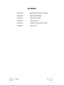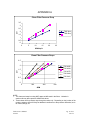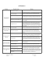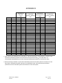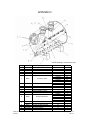
1
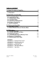
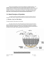
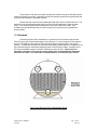
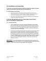
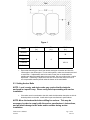
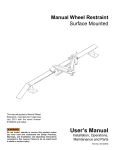
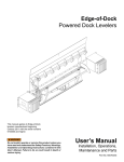
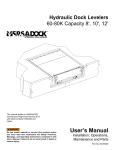
PENTAIR POOL PRODUCTS
THS SERIES FILTER
OWNER’S/OPERATOR’S MANUAL
TANKS ONLY
This manual covers the following filter tanks:
THS3461
THS3484
THS4272
THS4284
THS4296
WARNING: This manual contains critical safety information that must be furnished to the end
user. Failure to read and follow the instructions could result in serious personal injury and/or
major property damage.
Pentair Pool Products
1620 Hawkins Ave.
Sanford, NC 27330
Phone: 919-774-4151
Fax: 919-774-4841
TABLE OF CONTENTS
1.0 Basic Principles of Operation
1.1 Filtration - How Your Filter Works
1.2 Backwash
3
3
4
2.0 Installation and Assembly
2.1 Receiving and Inspecting
2.2 Locating the Filter
2.3 Setting Anchor Bolts
2.4 Install All Piping
2.5 Inspection of Components
2.6 Pressure Test System
2.7 Media Installation
5
5
5
6
7
7
8
9
3.0 Start-up and Operation
3.1 Backwash System
3.2 Return Filters to Normal Filtration Mode
9
9
9
4.0 Maintenance
4.1 Periodic Backwash
4.2 Periodic Inspection of filters
4.2 Draining the Filters
4.3 Installation/Removal of Manway Cover
4.4 Removal of Sand Media
4.5 Winterizing the filter tanks
APPENDIX
APPENDIX A:
APPENDIX B:
APPENDIX C:
APPENDIX D:
APPENDIX E:
APPENDIX F:
Tank Owner’s Manual
9/26/05
10
10
11
12
13
13
14
Pressure Drop Curves
Media Requirements
Troubleshooting
Backwash Log
Tank Specifications
Tank Parts
Pg. 2 of 23
Rev. D
Thank you for purchasing your new high rate sand filter from Paragon Aquatics. Your
new filter vessel is the best that money can buy, with its ability to operate for years with a
minimum amount of maintenance, as well as having excellent resistance to corrosion due to its all
fiberglass construction. In this manual you will learn the basic principles on how your new filter
operates, as well as how to install, operate, and maintain it. We suggest reading this manual
through once to familiarize yourself with it before proceeding with installation and operation.
Again, thank you for purchasing your high rate sand filter from Paragon Aquatics.
1.0 Basic Principles of Operation
Your high rate sand filter is designed to operate for years with a minimum amount of
maintenance when installed, operated and maintained in accordance with these instructions.
1.1 Filtration - How Your Filter Works
The basic principals of filter operation are as follows:
Dirty water enters the filter tank by being pumped under pressure through the influent
pipe and is distributed across the top of the inner tank chamber through diffusers. The water is
then forced downward through the sand filter bed. Dirt and debris is collected in the sand bed
allowing clean water to pass through. The clean water then passes through the collection laterals
and exits the filter through the effluent piping and is returned to the pool.
Tank Cross Section During Normal Filtration
Tank Owner’s Manual
9/26/05
Pg. 3 of 23
Rev. D
The pressure in the filter will increase and the flow of water through the filter will diminish
as dirt accumulates in the filter. Eventually, the filter will become obstructed enough with dirt that
it will become necessary to backwash the filter.
Please note that a filter removes suspended matter but it does not sanitize the pool. The
pool water must be sanitized and the water must be chemically balanced for optimum water
clarity. Your filtration system should be designed to meet your local health codes. Pool
chemistry is a specialized area and you should consult your local pool service specialist for
specific details.
1.2 Backwash
The basic principal of filter backwash is to reverse the flow of water through the filter.
This will remove the dirt and debris trapped in the filter bed. For this principal to work properly a
flow of 15-20 GPM per square foot of filter area should pass through the filter in the reverse
direction. This will help to fluidize the sand bed, loosening any solids trapped or compacted in the
bed, and then lifting the solids and transporting them out of the filter to waste. Usually a two to
five minute backwash duration is all that is necessary to clean the filter. Please note, it is
absolutely necessary to have a large enough waste line to accommodate the backwash
flow rate of the filter. A 6” waste line is recommended for all THS series filter vessels.
Tank Cross Section During Backwash Mode
Tank Owner’s Manual
9/26/05
Pg. 4 of 23
Rev. D
2.0 Installation and Assembly
If you have purchased the vessel(s) with the optional face piping kit, please
refer to documentation provided with the face piping kit.
2.1 Receiving and Inspecting
•
Upon receipt of filter(s), check the filter pallet(s) and auxiliary cartons for any
evidence of damage due to rough handling in shipment. If the filter(s) or any filter
components are damaged, NOTIFY FREIGHT CARRIER IMMEDIATELY.
•
Verify that you have all equipment contained on the Packing List(s) and that there is
no apparent damage to this equipment.
NOTE: BEFORE BEGINNING INSTALLATION, MAKE SURE PROPER
SAFETY EQUIPMENT IS BEING USED.
2.2 Locating the Filter
•
Prior to installing the filter(s), be sure to provide a PERMANENT LEVEL SLAB on
which to mount the filter. Preferably the slab should consist of reinforced concrete
poured in a form. Alternately, the filter(s) can be mounted on a platform constructed
of concrete block or brick. The platform must be able to support the weight of the
entire system (including media and water). DO NOT use sand to level the filter(s) or
for pump mounting, as it will wash away.
•
Position the concrete slab so that the instructions, warnings and the pressure gauges
on the system will be visible to the operator. It should be positioned so that the
piping connections, manway, and drain are convenient and accessible for servicing
and winterizing. If possible, ensure that the filter(s) are positioned to accommodate
any rough plumbing that may have been previously installed. Dimensions ‘A’ and ‘B’
in Figure 1 (next page) give the minimum filter to wall clearance in order to maintain a
6” minimum clearance between the tank and the wall (or other equipment). These
are only given as minimum distance guidelines. Tanks may be set up at larger
clearances if desired.
IMPORTANT: If a pre-glued diaphragm valve face piping kit has been purchased, it is
very important that the center to center (“C-C”) of the tanks be held to the dimension listed
in Figure 1. Failure to do so may cause the piping kit not to fit properly.
Tank Owner’s Manual
9/26/05
Pg. 5 of 23
Rev. D
Figure 1
Model
"A"
(in.)
"B"
(in.)
"C-C"
(in.)
THS3461
39
THS3484
THS4272
THS4284
6
6
46 1/4
THS4296
•
Ensure that the tank(s) are level, both across each pipe connection and from the
influent pipe to the effluent pipe. For two tank systems, make sure the tanks are level
to each other. If adjustments need to be made, loosen the nut underneath the
saddles and adjust the saddle placement as needed. Be sure to tighten the nut after
adjustment. If shimming is required to raise one end of the tank, be sure to use a
non-compressible material placed under the bottom of the tank saddle.
2.3 Setting Anchor Bolts
NOTE: Local, county, and state codes may require that the tanks be
anchored in a specific way. Please verify before proceeding with anchor
installation.
•
If the tanks are to be anchored to the slab, mark the holes when the tanks are in their
desired position on the slab. Install anchors per manufacturer’s specifications.
NOTE: Move the tanks aside before drilling for anchors. This may be
necessary in order to comply with the anchor manufacturer’s instructions,
and will avoid damage to the tanks and/or saddles during anchor
installation.
Tank Owner’s Manual
9/26/05
Pg. 6 of 23
Rev. D
2.4 Install All Piping
NOTE: Unless the optional piping kit was purchased from the filter
manufacturer, which provides the valves and piping to facilitate proper
backwash and filtration operation, the filter manufacturer cannot accept
responsibility for the design, installation, and operation of same. If an
optional face piping kit was purchased, please refer to the appropriate
manual provided with the kit for installation instructions.
•
Install all piping to provide proper filtration and backwash operation. We recommend
dry fitting all piping to ensure the proper fit.
•
The influent/effluent piping on the tanks are supplied with grooves for grooved
coupling connections. If a flanged connection is desired, a flange can be solvent
welded to the pipe on the tank. Use a PVC cement which has been NSF approved
for potable water applications. Apply according to manufacturer’s instructions.
Please note, certain modifications to the tank may void the manufacturer’s warranty.
Please contact manufacturer before proceeding with any modifications.
•
Once installed, all piping must be fully supported with bracing and hangers (by
others) to prevent damage to the system from weight and vibration.
2.5 Inspection of Components
Before performing the initial start up of the filter system, inspect the tanks and components to
ensure that no damage has occurred during the shipment of the vessel.
•
Check for loose, damaged, and missing laterals. If they
are loose, tighten them to hand tight, making sure that the
slots are facing down. Missing or damaged laterals can result
in returning the sand media from the filters to the pool, and
must be replaced.
Lateral
•
Check for loose, damaged, and missing diffusers.
These are a key component in flow distribution in the tank.
If they are loose, tighten them to hand tight. Missing or
damaged diffusers should be replaced.
Diffuser
Tank Owner’s Manual
9/26/05
Pg. 7 of 23
Rev. D
•
Check effluent piping grooved coupling connection to make sure it has not
become loose during shipping. If the coupling bolts have become loose, tighten
them.
•
Make sure automatic air relief is attached properly.
This mechanism assists in bleeding off air, which may
become trapped in the top of the tank. It is located on
the effluent pipe near the top of the tank, and should
be installed with the screen pointing up.
2.6 Pressure Test System
Automatic Air
Relief Assembly
WARNING: Filters should never be tested or subjected to air or
gas under pressure. All gases are compressible, and under pressure
create a danger. Severe bodily injury or property damage could occur if
the filter is subjected to air or gas pressure.
CAUTION: DO NOT exceed the maximum working pressure of the
vessel (50 psi) during testing or operation.
NOTE: DO NOT install media prior to pressure testing the system.
•
Install the manway cover (See section 4.3) and check that all piping connections,
manual air relief cap, and media drain cap are tight.
•
Flood the system with water. Make sure to bleed all air out of the tanks using the
manual air relief cap.
•
Pressurize the system. Caution: DO NOT exceed 50 psi.
•
Inspect all installed filtration equipment, focusing on solvent welded connections,
mechanical connections, and all tank penetrations.
NOTE: In the unlikely event that a leak is attributed to the vessel, consult
the equipment supplier before proceeding with any tank repairs.
Unauthorized repair attempts may void the factory warranty.
•
Drain the tank(s). It is important to read section (4.2) for proper instructions.
•
Make repairs if necessary. Before proceeding further, all repairs should be made at
this time.
NOTE: Do not perform the following step until the system is pressure
tested and all leaks are repaired (See Start-Up and Installation).
Tank Owner’s Manual
9/26/05
Pg. 8 of 23
Rev. D
2.7 Media Installation
•
Consult Appendix B for media specifications.
•
Partially fill the tank with water. This will help
prevent damage to the internal piping when
installing the gravel.
•
Install the gravel media. This layer should reach
to the top of the effluent laterals and be level.
•
Install the sand media. This layer should reach to
approximately the centerline of the tank. The sand
bed should be level and smooth. See pictures at
right for example.
3.0 Start-up and Operation
Above: Sandbed should
be flat and smooth when
sand is installed.
The following steps should be followed in the order shown for initial start up of the filter
system. Each section will be explained in more detail in the following pages.
1. Start system in backwash mode
2. Backwash each tank until clean
3. Start system in normal filtration mode
3.1 Backwash System
After the media is in place, reinstall the manway cover and fill the system with water. It is
again important that all air in the tank(s) be bled out using the manual air relief fitting on the top of
the tank(s). Once all of the air in the tanks is released, you may begin the initial backwash of the
tanks. Each tank should be backwashed for at least 5 minutes to remove any dust or dirt from
construction, as well as the “fines” in the media. When the wastewater coming from the
backwashed tank runs clear and is free of grit, the tank has been fully backwashed. Repeat this
for all tanks in the system. For some instances it may be necessary to repeat this backwash
procedure a second time in order to ensure that all “fines” have been removed.
Some things that should be noted during the backwash cycle:
•
•
Adequate backwash flow (Approx. 15-20 GPM per square foot of filtration area)
Quality of water flowing to waste (i.e. dirt, grit, etc.)
During a backwash the pressure through the system may differ from when it is in filtration
mode. This is normal, however it is important to make sure that the pressure does not exceed
the operating pressure of the tank.
3.2 Return Filters to Normal Filtration Mode
After backwashing is complete, run the system in normal filtration mode. Once this is
done, you should take note of the following:
•
Inspect pool water returns for sand. If the filter is returning sand to the pool, turn
off the system immediately. Refer to the Appendix C for further information.
Tank Owner’s Manual
9/26/05
Pg. 9 of 23
Rev. D
•
Verify pressure differential through the vessels is within an acceptable range.
Refer to Appendix A for pressure drops through the tanks only. Please be aware that
depending on where the pressure readings are taken from and the design of piping
system, the pressure drops through the system will be greater than what is shown in
Appendix A. Please consult the water circulation system designer for more details.
•
Note the pressure differential over the now clean filter system. If the system is
filtering within an acceptable pressure loss range, with the maximum pressure not to
exceed 50 psi, then the filter(s) can be considered clean. Please note the differential
pressure, as it may be needed later to determine backwash schedules. See section
4.1 for more details. Appendix D, which will be referred to later, provides a chart to
log these pressures into for future reference.
Congratulations, your filter is now ready to filter water. Please read the next section on
Maintenance to learn how to care for your new filter tank(s).
4.0 Maintenance
Although the “Smoothie” filter vessel is designed to operate for many years with little
maintenance, there are some items that should be periodically inspected. In certain situations,
periodic maintenance may be necessary. The following is a list of items that should be checked
periodically, as well as some maintenance items, which may need to be performed.
IMPORTANT: When performing maintenance, which requires entry into the
tank, VERIFY that all water sources to the tank are isolated and locked and
tagged out before entering tank. This is a confined space situation and all
rules and safety guidelines set forth by OSHA regarding such situations
should be strictly followed.
4.1 Periodic Backwash
If you have purchased the vessel(s) with the optional face piping kit, please
refer to documentation provided with the face piping kit.
The tanks need to be backwashed when the sand bed becomes clogged with debris from
the pool. There are a few different ways to determine when backwashing should occur. The
following are the most common methods, however depending on piping design; backwash
frequency can be determined in a different manor if desired.
•
Pressure Differential. When tanks become dirty, the pressure through them
increases. During the initial pressure test of your tank(s), the pressure through the
clean filter(s) should have been noted and recorded. This is your clean filter pressure
differential. When the filter pressure increases by 10 psi above this clean filter
pressure, the tank(s) should be backwashed.
•
Time Schedule. If desired, the system can be backwashed based on a time
schedule, such as once a week. This is up to the user as to when to backwash the
tank(s), however it is recommended that backwashing occur often enough so the
tanks don’t become too clogged. This may be especially necessary after periods of
increased bather load.
Tank Owner’s Manual
9/26/05
Pg. 10 of 23
Rev. D
When backwashing, it is important that there is:
•
Sufficient Backwash Time. It is recommended to backwash each tank for at least 5
minutes
•
Sufficient Backwash Flow Rate. The flow going through the tank in backwash
mode must be in the range of 15 to 20 GPM/ft2 in order to accomplish an adequate
backwash.
NOTE: It may be necessary in some instances to backwash the tanks more
than once to achieve a clean sand bed.
It is recommended that the influent and effluent pressures be recorded at the time of
each backwash. Appendix D has been provided to record these pressures. This information may
be useful in determining backwash frequency. It may also be useful in troubleshooting some
types of problems.
4.2 Periodic Inspection of filters
Part of the maintenance schedule that is suggested for these tanks is to check certain
areas of the filter tanks for signs of possible problems. Below are some key areas, which should
be inspected regularly.
•
Inspect Media Bed. The sand media bed should be inspected on a yearly basis, or
whenever the system is drained for maintenance. The sand bed should be smooth
and level. A difference in sand elevation between the highest and lowest points of
the bed that is 3” or more may indicate a problem which may require further
investigation. This may indicate that there may be damaged internal tank
components such as diffusers or laterals.
Above: Typical sand beds after draining tanks. Note the smooth, flat sand bed.
There are no signs of trenching or erosion.
Below: The sand beds shown below may indicate a problem. Note the trenches
and erosion of the media, which has developed.
Tank Owner’s Manual
9/26/05
Pg. 11 of 23
Rev. D
•
Inspect tanks for leaks. The system should be inspected periodically for leaking
around the influent/effluent piping penetrations, drain port, manual air relief fitting,
and on the outside shell of the tanks. A quick visual sight inspection is all that is
needed to accomplish this. In the unlikely event that a leak is attributed to the
vessel, consult the equipment supplier before proceeding with any tank
repairs. Unauthorized repair attempts may void the factory warranty.
•
Take note of system parameters (Influent/Effluent pressure). This is especially
important if you are not using an automatic backwash control system. These
parameters are prime indicators as to whether or not a backwash cycle needs to be
run. They should be checked every couple of days, particularly after periods of
increased bather load.
4.2 Draining the Filters
Some maintenance may require the filters to be drained of all water. To accomplish this
you must:
•
Make sure that the system is shut down. Isolate all water sources from the filter(s).
•
Remove the drain cap located on the bottom of the front of the tank. See figure
below for location.
•
Open the manual air relief on top of the tank. This will allow the water to drain
faster as well as to prevent the creation of a vacuum in the tank.
NOTE: A vacuum condition in the tanks can damage the tanks and
possibly other components in the filter system.
Figure 2
•
Replace Caps when water is drained.
Tank Owner’s Manual
9/26/05
Pg. 12 of 23
Rev. D
4.3 Installation/Removal of Manway Cover
NOTE: It is important that the manway yokes never be removed during
operation of the tanks. The tanks should be drained before removing
manway cover.
4.3.1
4.3.2
Removal:
•
•
Drain the tanks. See section 4.2 for instructions.
Remove one yoke bolt and yoke. This will require a 1
1/8” wrench. Loosen the second bolt, but do not
remove the second yoke.
•
Remove cover from tank. Rotate remaining yoke90°
and push cover into tank. Turn the cover so that it will
pass through the manway opening and remove the
cover. Make sure the manway gasket is with the cover.
If not, look for it on the manway opening or inside the
tank.
Installation:
*Manway cover may differ
from picture below
Gasket ring
•
Ensure there are no tools, construction materials, or
foreign objects in the tank.
•
Clean the sealing surfaces of the cover and manway opening. Make sure they
are free of dirt and debris.
•
Install gasket ring on manway cover. See picture at
right for correct location.
•
Maneuver the cover back into the tank so it fits back in
the manway opening. Follow removal directions in
reverse order.
•
Install yokes, bolts, and washers. Make sure the yokes
are in the proper locations. See picture at right.
Correct yoke orientation
•
Snug yoke bolts. Tighten bolts one full turn past hand tight. If manway leaks during
refilling of system, tighten bolts in quarter turn increments until leak stops. After filter
is at operating pressure, yokes will be loose due to internal pressure. Snug bolts until
yokes no longer move. DO NOT exceed 15 ft/lbs of torque.
4.4 Removal of Sand Media
The sand media in the filter should be removed when:
•
Media bed has become contaminated. The media bed can become contaminated
due to the introduction of an unwanted substance into the water, such as fecal
matter, chemicals, etc. While the filters will take out the particulate matter of the
contaminate and prevent it from returning to the body of water, the contaminate will
become embedded in the media. This can affect pool chemistry.
Tank Owner’s Manual
9/26/05
Pg. 13 of 23
Rev. D
•
Filters need to be moved from their current location. While these tanks are
designed to withstand internal pressure, they are not designed to be transported with
the added weight of the media inside of them. It is therefore necessary to remove as
much media as possible before relocating the filters.
•
Inspections/repairs need to be made to inside of tank or internal components.
In order to reach certain components or areas of the tank, the sand has to be partially
or removed. These areas include laterals, effluent piping, media drain assembly,
inside walls of the filter.
If you need to remove the media the tanks must be drained first, see Draining Filters section.
After draining the filters, remove the manway cover (see Section 4.3.1). Removal can be done by
a variety of means, from using an ordinary shovel, to adding water to the sand and removing the
slurry with a pump truck. It is important that if using shovels or other devices with edges,
corners, etc. that care be taken to not scratch the inside walls of the tank. The inside walls
are coated with a material that protects the water from exposure to the fiberglass walls of the
tanks.
Remove only as much material as required to perform any maintenance operations. If all of
the sand needs to be removed for the purpose of replacement due to contamination, be sure to
rinse out the tank with clean water. It may be necessary to backwash the tank(s) after rinsing to
remove sand stuck in the laterals. Follow the backwash procedures outlined earlier in this
section.
4.5 Winterizing the filter tanks
In areas where the tanks will not be in service during the winter months, or where tanks
may see freezing or below freezing temperatures, it is recommended that the tank(s) be
winterized. This will protect the tank(s) from being damaged due to ice expansion. Some items
that may be damaged due to this may include internal piping, internal components, and tank
walls. Below are the steps that should be performed when winterizing the tank(s):
•
Thoroughly backwash each filter to remove foreign contaminates from the
filter bed prior to draining the system
•
Shut off all electrical power to the filter system.
•
Drain the tanks by removing the drain plug from the tank (See Section 4.2).
Opening the manual air relief valve cap will help in allowing the water to drain
out of the filters, as well as preventing a vacuum condition from occurring.
•
When the water is drained from the system, drain all of the water in the
backwash line.
•
Loosen any flanges in low-lying sections of piping to completely drain the
system of water.
•
Store any plugs/caps removed near the filter and mark all flanges that have
been loosened so that they may be reinstalled and tightened at time of start
up.
Tank Owner’s Manual
9/26/05
Pg. 14 of 23
Rev. D
APPENDIX
APPENDIX A
PRESSURE DIFFERENTIAL CURVES
APPENDIX B
MEDIA REQUIREMENTS
APPENDIX C
TROUBLE SHOOTING
APPENDIX D
BACKWASH LOG
APPENDIX E
GENERAL TANK SPECIFICATIONS
APPENDIX F
TANK PARTS
Tank Owner’s Manual
9/26/05
Pg. 15 of 23
Rev. D
APPENDIX A
Clean Filter Pressure Drop
3.5
3
psi
2.5
2
THS 34xx
1.5
THS 42xx
1
0.5
0
0
5
10
15
20
25
GPM/sq.ft
Clean Filter Pressure Drops
2.5
2
THS 4296
THS 4284
psi
1.5
THS 4272
1
THS 3484
THS 3461
0.5
0
0
200
400
600
GPM
NOTE:
1. The charts are based on using NSF approved #20 sand in the filters. Variation in
sand media may affect pressure differential values.
2. These charts are for pressure drop through the tanks only. Depending on the location of the
pressure gauges, there will likely be additional contributors to the pressure differential, such
as valves, fittings, etc.
Tank Owner’s Manual
9/26/05
Pg. 16 of 23
Rev. D
APPENDIX B
Filter Model
Filter Area
2
(Ft )
Total Media
Requirement
3
(Ft )
Sand Media
3
(Ft )
Gravel Media
3
(Ft )
(Optional)
THS3461
13.5
16.6
(1660 lbs.)
11.1
(1110 lbs.)
5.5
(550 lbs.)
THS3484
THS4272
23.5
19.0
(2350 lbs.)
29.1
19.7
(2910 lbs.)
34.6
14.4
(1440 lbs.)
22.1
(2210 lbs.)
26.7
(3990 lbs.)
Media Type
Media Size
Specific Gravity
Uniformity
Coeffictient
Pea Gravel
1/4" - 1/8"
Greater than 2.5
Less than 1.5
Sand
#20 Standard
.018"-.022"
(.45mm-.55mm)
2.65
Less than 1.5
39.9
11
8 5/16
(700 lbs.)
7.5
(860 lbs.)
THS4296
7 1/2
7.0
31.3
(3130 lbs.)
(3460 lbs.)
Gravel
Depth
(in.)
(910 lbs.)
(750 lbs.)
23.2
Sand Bed
Depth
(in.)
9.1
27.1
(2710 lbs)
THS4284
Freeboard
Height
(in.)
8 1/2
16
8.6
NOTE:
1. All gravel and sand should be washed and screened. It should contain less than
1% of loam, clay, sand, shells, dirt organic impurities or other foreign matter.
2. It is recommended that all media used be NSF approved.
Tank Owner’s Manual
9/26/05
Pg. 17 of 23
Rev. D
7 1/2
APPENDIX C
Problem
Possible Cause
Solution
Maintain pool chemistry. Consult pool service technician
1. Water chemistry not in balance
Verify media size with media vendor. Consult Appendix B of this manual for proper
media sizing. If the media is the incorrect size, replace with proper media.
2. Incorrect media installed
3. Filter sytem not being backwashed properly
Source water not
sufficiently clear
The tank(s) may not have been backwashed enough upon initial start-up. Repeat
the backwash procedure for initial start-up (see Start-up and Operation section).
Backwash each tank twice to ensure that the media bed is clean and free of debris.
Adjust the flowrate throught the filters. These filters are designed to operate at a
2
2
4. Rate of flow in excess of 20 GPM/ft of filter
area
maximum of 20 GPM/ft . If flow rates are in excess of this, the media bed will not
perform as designed.
5. Inadequate turnover rate
The turnover rate is the amount of time it takes the filters to pass the entire volume
of the pool through the filter system. Filtration systems for pools are typically
designed to operate at a turnover rate of 1-6 hours typically depending on the
application and appropriate codes. If the filter system is filtering the water too slow,
dirt and debris can build up faster than the water is cleaned. The flow through the
filters may need to be increased. Consult the manufacturer before changing the
filtration parameters.
1. Incorrect media installed
Filtration media being
discharged into the filtered
body of water
2. Damaged effluent piping/lateral
1. Filter sytem not being backwashed properly
Verify media size with media vendor. Consult Appendix B of this manual for proper
media sizing. If the media is the incorrect size, replace with proper media.
The tank(s) must be drained of water (see Maintenance section) and all media
removed. Once this is done, an inspection of all internal piping should be
performed. If any laterals are broken, cracked, or missing, they should be
replaced. If the main effluent pipe in the tank is cracked, consult the manufacturer
for repairs.
The tank(s) may not have been backwashed enough upon initial start-up,
backwashes may be too infrequent, or there may not be enough backwash flow.
Check the backwash flow rate on the waste pipe to verify that enough backwash
2
flow is present. A minimum of 15 GPM/ft of filtration area is recommended.
High filtration pressure
differential
2. Impacted sand bed
1. Backwash flow rate is too high
Excessive sand media
being lost to waste drain
2. Incorrect media installed
1. Improperly tightened assembly
Leak at manual air relief,
manway, or tank drain 2. Dirt or contamination on sealing surface
port
3. Damaged part
Tank Owner’s Manual
9/26/05
Sometimes the sand media may become compressed, which inhibits the flow of
water throught it. If an impacted sand bed is suspected, the tanks should be
drained and the media should be loosened by turning over the top 6"-10" of sand.
After this, a backwash cycle should be run before returning the filter to filtration
mode.
If the flow rate is too great, it will force some of the sand media out through the
diverters and into the waste drain. Reduce the flowrate slightly to the filters when
performing a backwash.
Verify media size with media vendor. Consult Appendix B of this manual for proper
media sizing. If the media is the incorrect size, replace with proper media.
With the pump off, isolate the tanks from the system and relieve the tank of any
pressure using the manual air relief valve. If leak has occurred in an area which is
below the water level in the tank, drain the tank until water line is below the leak
(see Maintenance section). Remove the assembly and inspect the sealing
surfaces for dirt and debris. Clean all sealing surfaces. If the assembly is still in
usable condition, replace the assembly and pressure test the system (see Start-up
and Operation section). If the assembly appears broken or defective, replace with
a new factory part (see Appendix X for part number). After replacement pressure
test the system before restoring it to normal filtration mode.
Pg. 18 of 23
Rev. D
APPENDIX D
Pressures for
Dirty Filter
(Psi)
Date
Start-up
Time
Start-up
Influent
n/a
Effluent
n/a
∆P Dirty Filter
=(Influent - Effluent)
(Psi)
Pressures for
Backwashed Filter
(Psi)
Influent
∆P Clean Filter
=(Influent - Effluent)
(Psi)
Effluent
n/a
1. After performing the backwash for the initial start up, and returning the filter to normal operation, record the clean
filter influent and effluent pressures into the first line of the chart and calculate ∆P for a clean filter. It is
recommended that backwashing occur when the pressure differential increases by 10 Psi from this value.
2. Before perfoming a backwash, log the influent and effluent pressures of the filter system and calculate ∆P for the
dirty system. Backwash the system and return to normal filtration mode. Record the influent and effluent
pressures for the now clean filter system and calculate ∆P for the clean system.
Tank Owner’s Manual
9/26/05
Pg. 19 of 23
Rev. D
APPENDIX E
Tank Owner’s Manual
9/26/05
Pg. 20 of 23
Rev. D
SS-THS3461 SPEC SHEET HERE
Tank Owner’s Manual
9/26/05
Pg. 21 of 23
Rev. D
SS-THS SPEC SHEET HERE
Tank Owner’s Manual
9/26/05
Pg. 22 of 23
Rev. D
APPENDIX F
NOTE: Drawing is for reference only.
Ref # Part Number
1
B4848BL
2
B4856
3
B4852ABL
4
B4951
5
B4860
Description
Tank Saddle, Black
Yoke, Dog (Manway)
Glass Filled Manway Cover (Black)
HHMB, 3/4" x 4" T316 S/S
3/4" Flat Washer, T316 S/S
6
B4804
7
B4803
3 1/2" Effluent Lateral
8
9
10
11
12
B4980
B4981
B4951
**
**
Media Dump Assembly
1 1/2" NPT Tank Adapter
Manway O-Ring
Effluent Manifold w/ Laterals
Influent Manifold w/ Laterals
13
B4806
14
15
16
17
18
B4570
B4572
B4578
B4974BAN
B4970BAN
B4979BAN
Tank Owner’s Manual
9/26/05
10" Effluent Lateral
Shower Head Diffuser
4" Grooved Coupling Assembly
6" Grooved Coupling Assembly
Automatic Air Relief Assembly
1/2" Manual Air Relief Cap
1/2" Threaded Nipple
1/2" Bulkhead Fitting
Tank Used On
Quantity
All
2
All
2
All
1
All
2
All
2
THS3461
14
THS3484
20
THS4272
18
THS4284
24
THS4296
28
THS3461 - THS3484
2
THS4272 - THS4296
3
1
All
1
All
All
1
**
1
**
1
THS3461
8
THS3484
10
THS4272
10
THS4284
12
THS4296
14
THS3461 - THS3484
1
THS4272 - THS4296
1
All
1
All
1
All
1
All
1
Pg. 23 of 23
Rev. D