1
Part Number: 80JJ0103
©2008 Pella Corporation
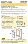
INSTALLATION INSTRUCTION - INSTRUCCIONES DE INSTALACION
FOR CLAD HINGED PATIO DOOR WITH ADJUSTABLE HINGES
PARA LA PUERTA PARA PATIO REVESTIDA, CON BISAGRAS ADJUSTABLES
$PSOFS
'MBTIJOH
5BQF
4JEF
'MBTIJOH
5BQF
'JO
$PSOFS
%PPS5PQ
/BJMJOH'JO
5PQ
'MBTIJOH
5BQF $PSOFS
'MBTIJOH
5BQF
8BUFS
3FTJTUJWF
#BSSJFS
4IFBUIJOH
'SBNJOH
0QUJPOBM
/BJMJOH'JO
4JEF
'MBTIJOH
5BQF
%PPS#PUUPN
4JMM4VQQPSU
4JMM'MBTIJOH5BQF
4JMM'MBTIJOH5BQF
Always read the Pella® Limited Warranty before purchasing or installing Pella products. By
installing this product, you are acknowledging that this Limited Warranty is part of the terms of the
sale. Failure to comply with all Pella installation and maintenance instructions may void your Pella
product warranty. See Limited Warranty for complete details at http://warranty.pella.com.
These instructions were developed and tested for use with typical wood frame wall construction in
a wall system designed to manage water. These instructions are not to be used with any other
construction method. Installation instructions for use with other construction methods, multiple
units or bow and bay windows, may be obtained from Pella Corporation or a local Pella retailer,
or by visiting http://www.pella.com. Building designs, construction methods, building materials,
and site conditions unique to your project may require an installation method different from
these instructions and additional care. Determining the appropriate installation method is the
responsibility of you, your architect, or construction professional.
YOU WILL NEED TO SUPPLY:
TOOLS REQUIRED:
s#EDAROR)MPERVIOUSSHIMSSPACERSTO
sGALVANIZEDROOlNGNAILSLB
sDNAIL
s#LOSEDCELLFOAMBACKERRODSEALANTBACKERTOFT
s0ELLA® SmartFlash™ foil backed butyl window and door
flashing tape or equivalent
s(IGHQUALITYEXTERIORGRADEPOLYURETHANEORSILICONE
SEALANTTOTUBESPERDOOR
s'REAT3TUFF™ Window and Door Insulating Foam
Sealant by the Dow Chemical Company or equivalent
low pressure polyurethane window and door foam - DO
./4USEHIGHPRESSUREORLATEXFOAMS
s0ELLAALUMINUMSILLSUPPORTORXWOODBLOCKING
s)NTERIORTRIMANDORJAMBEXTENSIONSTOFT
s4APEMEASURE
4&"-"/5
4&"-"/5
1
s,EVEL
s3QUARE
s(AMMER
s3TAPLER
s3CISSORSORUTILITYKNIFE
s3CREWDRIVERS
0HILLIPSANDSMALLmATBLADE
s!LLENWRENCH
s$RILL
s3EALANTGUN
REMEMBER TO USE APPROPRIATE PERSONAL PROTECTIVE EQUIPMENT.
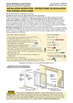
ROUGH OPENING PREPARATION
A. Verify the opening is plumb and level.
Note: It is critical that the bottom is level.
B. Verify the door will fit the opening. Measure all
four sides of the opening to make sure it is 3/4"
larger than the door in width and 1/2" larger in
height. On larger openings measure the width
and height in several places to ensure the header
or studs are not bowed.
Note: 1-1/2" or more of solid wood blocking is
required around the perimeter of the opening.
Fix any problems with the rough opening
before proceeding.
*OUFSJP
S
£
*OUFSJP
S
£
C. Cut the water resistive barrier.
8BUFS3FTJTUJWF#BSSJFS
TUDVU
SEDVU
£
OE
DVU
UIDVU
.BLFBDVUVQGSPN
FBDIUPQDPSOFSBUB¡
BOHMFUPBMMPXUIFXBUFS
SFTJTUJWFCBSSJFSUPCF
MBQQFEPWFSUIFmOBUUIF
IFBEPGUIFEPPS
&YUFSJP
S
£
D. Fold the water resistive barrier (1D). Fold side flaps into
the opening and staple to inside wall. Fold top flap up and
temporarily fasten with flashing tape.
E. Apply sill flashing tape #1. Cut a piece of flashing tape 12"
longer than the opening width. Apply at the bottom of the
OPENINGASSHOWN%SOITOVERHANGSTOTHEEXTERIOR
Note: The tape is cut 12" longer than the width so that it will
extend 6" up each side of the opening.
F. Tab the sill flashing tape and fold. Cut 1" wide tabs at each
CORNERFROMEACHSIDEOFCORNER&&OLDTAPETOTHE
EXTERIORANDPRESSlRMLYTOADHEREITTOTHEWATERRESISTIVEBARRIER
'Apply sill flashing tape #2. Cut a piece of flashing tape 12" longer
THANTHEOPENINGWIDTH!PPLYATTHEBOTTOMOVERLAPPINGTAPE
BYATLEAST$/./4ALLOWTHETAPETOEXTENDPASTTHEINTERIOR
FACEOFTHEFRAMING'
In-swing doors:)FTHEWALLDEPTHISGREATERTHANADDATHIRD
piece of flashing tape. The flashing tape should come to within 1"
of the interior face of the framing.
£
£
£
Note: The flashing tape may not fully cover the framing
members. When using the optional fin at the bottom of the door,
do not install the aluminum sill support or wood blocking until
after the doors have been installed in the rough opening.
(Attach the aluminum sill support or wood blocking to the
EXTERIOROFTHEBOXPLATETOSUPPORTTHEEDGEOFTHEDOORSILL
Place the sill support flush with the subfloor.
2
£
SETTING AND FASTENING THE DOOR
A. Remove plastic wrap and cardboard packaging from door. DO
NOT remove plastic shipping spacers. The shipping spacers will help
keep the door square during installation. DO NOT unlock or open the
door until it is fully fastened.
Ó
Note: If screens, grilles or hardware are removed from the door at
this time, label them and store them in a protected area.
B. Fold out installation fin to 90°. Be careful not to remove or tear the
lNCORNERS
Note: If the fin is not at 90°, the door will not line up correctly on
the interior. If using the optional fin at the sill, apply the fin and fin
corners, then proceed to Step D. Sealant lines from Step C are not
required when using the optional fin at the sill.
C. Place three 3/8" beads of sealant. 4HElRSTBEADSHOULDBE
APPROXIMATELYFROMTHEEXTERIOROFTHEROUGHOPENINGTHESECOND
bead should be placed so it is under the wood interior threshold of the
door. Placement will vary depending on wall thickness and door
type. Place a third bead of sealant in the groove of the sill support
Ó
ORFROMTHEEXTERIOREDGEOFTHEWOODBLOCKING
TWO OR MORE PEOPLE WILL BE REQUIRED FOR THE
FOLLOWING STEPS.
D. Insert the door from the exterior of the building.
DO NOT slide the bottom of the door into the opening. Sliding
will damage the sealant lines. Place the bottom of the door at the
bottom of the opening, then tilt the top into position. Center
the door between the sides of the opening to allow clearance for
SHIMMINGANDINSERTONEROOlNGNAILINTHElRSTHOLEFROMTHE
CORNERONEACHENDOFTHETOPNAILINGlN4HESEAREUSEDTOHOLD
the door in place while shimming it plumb and square.
Ó
&YUFSJP
S
E. Plumb and square door. Place shims at each hinge and lock
strike location between the door and the sides of the opening.
)NSERTSHIMSINOTHERLOCATIONSASNEEDEDSTARTINGUPFROMTHE
bottom of the door to square it in the opening. Make sure that the
REVEALAROUNDTHEDOORSISEQUAL/NDOUBLEDOORSMAKESURETHAT
panels are even across the bottom.
Ó
&YUFSJP
S
Note: On center latch double doors the lock strike will not be
shimmed since it is located in the center of the unit. DO NOT
over shim.
F. Check the interior reveal. Make sure the
measurement from the interior face of the door
to the interior face of the wall is equal at several
points around the door.
Ó
Note: If the dimensions are not equal, check
to make sure the fins are folded out to 90° at
all points.
£ -
Óä Î
ä {ä Ó
Î
xä È
ä Çä
S
Ó
'&ASTENTHEDOORTOOPENINGBYDRIVINGGALVANIZEDROOlNG
NAILSINTOEACHPREPUNCHEDHOLEINTHENAILINGlN
Ó
Note: Make sure the fin corner is lying as flat as possible.
When using the optional fin at the sill, attach
the aluminum sill support or wood blocking
under the sill of the door before proceeding
to Step H.
(#AREFULLYOPENTHEDOORSANDREMOVEALL
shipping spacers.
*OUFSJP
Ó
&YUFSJP
Ó
S
Note: Be sure to remove the spacers from
the bottom edge of the door panel.
Double doors with center latch: Designer Series Only: Use the
construction handle to operate the active door panel. Operate the
flushbolts per the instructions on the label on the strike located on
the astragal.
Architect Series Only: Use the construction handle to operate both
the active and passive door panels.
I. Out-swing doors: Place a dab of sealant in each of the preDRILLEDHOLESINTHEBOTTOMOFTHEDOORFRAMETHENINSERTAX
STAINLESSSTEELSCREWPROVIDEDINTOEACHHOLE
Note: Single doors will have two pre-drilled holes, double
doors will have four.
I1. Out-swing double doors only: Place a dab of sealant into the
center hole of the strike plate located at the sill of the door.
)NSTALLAXmATHEADSTAINLESSSTEELWOODSCREWPROVIDED
into this hole.
Ó
*OUFSJP
S
Ó
Ó
Note: For masonry floors, use a #8 masonry screw instead of
the wood screw.
J. On center latching (double) doors: Place shims at the top of the door frame above the center
STRIKEPLATE3ECURETHESHIMSBYINSERTINGAXmATHEADSTAINLESSSTEELSCREWINTOTHEUPPER
door frame through the center hole of the strike plate and the shims into the rough opening.
J1. On center hinged double doors: Insert and attach shims directly above the astragal in the center of
the unit.
+ /NEACHHINGESTARTINGATTHETOPINSERTALONGSCREWPROVIDEDINTOTHEOPENSCREWHOLEMake
sure that the screw passes through the shims and into the structural framing.
Note: This step does not apply to center hinge double doors.
L. Check door operation. Open and close the door to check for proper operation. Make
sure the door will latch correctly.
Note: If there are any problems with the operation, recheck and
adjust the reveal.
M. Adjust the reveal if needed. The door panels have adjustable hinge
LEAFS5SINGAALLENWRENCHTURNTHECENTERSCREWCLOCKWISETO
increase the space between the hinge side of the frame and the door
panel, or counter clockwise to increase the space between the door
panel and the lock side of the frame. DO NOT turn the screws more
than a 3/4 turn in either direction. In some cases it may be necessary
to loosen and then tighten the top and bottom hinge screws to obtain
full hinge adjustment. If necessary, loosen the top and bottom screws,
and immediately retighten them. With the screws retightened, turn the
adjustment hinge screw. If the hinge will not adjust any further then
it is adjusted as far as it will go. If more clearance is needed adjust the
shims between the frame and the rough opening.
Note: DO NOT adjust the hinge with the top and bottom screws
loose; this could force the hinge to adjust beyond its design capability
which can cause the hinge to bind, damage the hinge and/or pull out
the screws. A 3/4 turn of the center screw provides approximately
1/16" adjustment.
N. On doors with a lock strike in the side,DRILLADIAMETERXDEEP
PILOTHOLETHROUGHTHELOCKSTRIKEANDINTOTHEROUGHOPENING)NSERTAX
SCREWPROVIDEDINTOTHEPILOTHOLEMAKINGSURETHATITPASSESTHROUGHTHE
shim and into the stud.
Note: This step does not apply to center latching double doors.
O. Install a #8 x 3" flat head stainless steel screwINTOTHEHOLELOCATEDAPPROXIMATELY
FROMTHETOPOFTHEDOORFRAMEONTHELATCHSIDEOFTHEFRAME
3
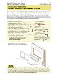
INTEGRATING THE DOOR TO
THE WATER RESISTIVE BARRIER
Note: The flashing tape must be applied approximately 1/2"
onto the frame cladding at the jambs and head. Pre-folding the
tape at 1/2" before removing the paper backing will make it
easier to apply the tape correctly. If the siding is less than 1/2"
thick, adjust the dimension of the fold so the exterior sealant
line will cover the exterior edge of the tape.
A. Apply side flashing tape. Cut two
pieces of flashing tape 4" longer than
the frame height of the door. Apply one
piece 1/2" onto the frame cladding,
OVERTHENAILINGlNANDONTOTHEWATER
resistive barrier on each side. The tape
SHOULDEXTENDABOVETHETOPOFTHE
door and 2" below the bottom of the
DOOR0RESSTHETAPEDOWNlRMLYWHILE
FOLDINGDOWNTHEEXCESSTAPEATTHETOP
and bottom of the door.
&YUFSJP
S
Î
Ó
Ó
B. Apply top flashing tape. Cut a piece of flashing tape long
ENOUGHTOGOACROSSTHETOPOFTHEDOORANDEXTENDAT
least 1" past the side flashing tape on both sides. Apply
the tape 1/2" onto the frame cladding, over the top
NAILINGlNASSHOWN&OLDTHEOVERLAPPINGTAPEDOWN
ANDPRESSALLTAPEDOWNlRMLY
Note: The top flashing tape must overlap the
side flashing tape to prevent water from getting
behind it.
Î
C. Fold down top flapOFWATERRESISTIVEBARRIER#
&YUFSJP
S
D. Apply flashing tape to diagonal cuts. Cut pieces of
flashing tape at least 1" longer than the diagonal cuts
in the water resistive barrier. Apply the tape covering
the entire diagonal cut in the water resistive barrier
at both upper corners of the door.
Note: Be sure to overlap the top corners (3D).
4
Î
Î
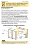
INTERIOR SEAL
Caution: Ensure use of low pressure polyurethane window and door insulating foams and strictly
follow the foam manufacturer’s recommendations for application. Use of high pressure foams or
improper application of the foam may cause the door frame to bow and hinder operation.
A. Apply insulating foam sealant. From the interior,
INSERTTHENOZZLEOFTHEAPPLICATORAPPROXIMATELY
deep into the space between the door and the rough
opening and apply a 1" deep bead of foam. This
WILLALLOWROOMFOREXPANSIONOFTHEFOAMANDWILL
MINIMIZESQUEEZEOUT)FUSINGFOAMOTHERTHAN'REAT
Stuff ™ Window and Door Insulating Foam Sealant by
the Dow Chemical Company, allow the foam to cure
COMPLETELYUSUALLYTOHOURSBEFOREPROCEEDING
TOTHENEXTSTEP
Note: DO NOT completely fill the space from the
back of the fin to the interior face of the opening.
*OUFSJP
S
{
B. Check the door operation by opening and closing the door.
Note: If the door does not operate correctly, check to make sure it is still plumb, level,
square and that the sides are not bowed. If adjustments are required, remove the foam
with a serrated knife. Adjust the shims, and reapply the insulating foam sealant.
5
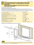
SEALING THE DOOR TO THE EXTERIOR WALL CLADDING
When applying siding, brick veneer or other exterior finish material, leave adequate space between
the door frame and the material for sealant. Refer to the illustration that corresponds to your
finish material.
Note: The sealant details shown are standard recommendations from the sealant industry. Contact
your sealant supplier for recommendations and instructions for these and any other applications.
#3*$,7&/&&3
7*/:-45&&4*%*/(
#BDLFS3PEBOE
4FBMBOUUZQJDBM
$MFBSBODF
"DDFTTPSZ(SPPWF
*OTVMBUJOH
'PBN
1FSJNFUFS4FBMBOU
NVTUFYUFOEUP
SPPNTJEFPG
"DDFTTPSZ(SPPWF
#BDLFS3PEBOE
4FBMBOUUZQJDBM
$MFBSBODF
"DDFTTPSZ(SPPWF
*OTVMBUJOH
'PBN
1FSJNFUFS4FBMBOU
NVTUFYUFOEUP
SPPNTJEFPG
"DDFTTPSZ(SPPWF
800%4*%*/(
8*5)53*.
800%
4*%*/(
.JO
.JO
4FBMBOUUZQJDBM
4FBMBOUUZQJDBM
$MFBSBODF
"DDFTTPSZ
(SPPWF
*OTVMBUJOH
'PBN
$MFBSBODF
"DDFTTPSZ(SPPWF
*OTVMBUJOH
'PBN
1FSJNFUFS4FBMBOU
NVTUFYUFOEUP
SPPNTJEFPG
"DDFTTPSZ(SPPWF
.JO
A. Install the hardware. Refer to the instructions
INCLUDEDINTHEHARDWAREBOX
B. Insert closed cell foam backer rod into the space
AROUNDTHEDOORSOTHEREISAPPROXIMATELYTO
CLEARANCEBETWEENTHEBACKERRODANDTHEEXTERIORFACE
of the door.
Note: Backer rod adds shape and depth for the
sealant line.
C. Apply a bead of high quality exterior grade sealant
to the entire perimeter of the door. At each end of
the bottom of the door, insert sealant into the spaces
between the bottom of door and the sill support and
connect it to the perimeter sealant.
D. Shape, tool and clean excess sealant.7HENlNISHED
the sealant should be the shape of an hourglass.
Note: This method creates a more flexible sealant
line capable of expanding and contracting.
E. Remove plastic guards at the base of the door
once construction is complete.
x
x
INTERIOR FINISHING
)FPRODUCTSCANNOTBElNISHEDIMMEDIATELYCOVERWITHCLEARPLASTICTOPROTECTFROMDIRTDAMAGEAND
MOISTURE2EMOVEANYCONSTRUCTIONRESIDUEBEFORElNISHING3ANDALLWOODSURFACESLIGHTLYWITH
GRITORlNERSANDPAPER$/./4USESTEELWOOL"%#!2%&5,./44/3#2!4#(4(%',!33
Remove sanding dust.
0ELLAPRODUCTSMUSTBElNISHEDPERTHEBELOWINSTRUCTIONSFAILURETOFOLLOWTHESEINSTRUCTIONSVOIDSTHE
Limited Warranty.
s/NCASEMENTANDAWNINGSITISOPTIONALTOPAINTSTAINORlNISHTHEVERTICALANDHORIZONTALSASHEDGES
s/NSINGLEHUNGANDDOUBLEHUNGDONOTPAINTSTAINORlNISHTHEVERTICALSASHEDGESANYlNISHON
THEVERTICALSASHEDGESMAYCAUSETHESASHTOSTICKITISOPTIONALTOPAINTSTAINORlNISHTHEHORIZONTAL
sash edges.
s/NPATIODOORSITISOPTIONALTOPAINTSTAINORlNISHTHEVERTICALANDHORIZONTALPANELEDGES
Note: To maintain proper product performance do not paint, finish or remove the weatherstripping, mohair dust pads, gaskets or vinyl parts. Air and water leakage will result if these parts
are removed. After finishing, allow venting windows and doors to dry completely before closing
them.
0ELLA#ORPORATIONISNOTRESPONSIBLEFORINTERIORPAINTANDSTAINlNISHIMPERFECTIONSFORANYPRODUCT
THATISNOTFACTORYAPPLIEDBY0ELLA#ORPORATION5SEOFINAPPROPRIATElNISHESSOLVENTSBRICKWASHOR
cleaning chemicals will cause adverse reactions with window and door materials, and voids the Limited
Warranty.
&ORADDITIONALINFORMATIONONlNISHINGSEETHE0ELLA/WNERgS-ANUALORGOTTOwww.pella.com.
EXTERIOR FINISH
4HEEXTERIORFRAMEANDSASHAREPROTECTEDBYALUMINUMCLADDINGWITHOURTOUGH%NDURA#LAD® or
%NDURA#LAD0LUSBAKEDONFACTORYlNISHTHATNEEDSNOPAINTING#LEANTHISSURFACEWITHMILDSOAP
and water. Stubborn stains and deposits may be removed with mineral spirits. DO NOT use abrasives.
DO NOT scrape or use tools that might damage the surface.
5SEOFINAPPROPRIATElNISHESSOLVENTSBRICKWASHORCLEANINGCHEMICALSWILLCAUSEADVERSEREACTIONS
with window and door materials and voids the Limited Warranty.
CARE AND MAINTENANCE
Care and maintenance information is available in the Pella Owner’s Manual. You can obtain an owner’s
manual by contacting your local Pella retailer. This information is also available on www.pella.com.
IMPORTANT NOTICE
"ECAUSEALLCONSTRUCTIONMUSTANTICIPATESOMEWATERINlLTRATIONITISIMPORTANTTHATTHEWALLSYSTEMBE
designed and constructed to properly manage moisture. Pella Corporation is not responsible for claims
ORDAMAGESCAUSEDBYANTICIPATEDANDUNANTICIPATEDWATERINlLTRATIONDElCIENCIESINBUILDINGDESIGN
CONSTRUCTIONANDMAINTENANCEFAILURETOINSTALL0ELLAPRODUCTSINACCORDANCEWITH0ELLASINSTALLATION
INSTRUCTIONSORTHEUSEOF0ELLAPRODUCTSINWALLSYSTEMSWHICHDONOTALLOWFORPROPERMANAGEMENT
of moisture within the wall systems. The determination of the suitability of all building components,
including the use of Pella products, as well as the design and installation of flashing and sealing systems
are the responsibility of the Buyer or User, the architect, contractor, installer, or other construction
professional and are not the responsibility of Pella.
Pella products should not be used in barrier wall systems which do not allow for proper management of
MOISTUREWITHINTHEWALLSYSTEMSSUCHASBARRIER%XTERIOR)NSULATIONAND&INISH3YSTEMS%)&3ALSO
KNOWNASSYNTHETICSTUCCOOROTHERNONWATERMANAGEDSYSTEMS%XCEPTINTHESTATESOF#ALIFORNIA
.EW-EXICO!RIZONA.EVADA5TAHAND#OLORADOPella makes no warranty of any kind on and
assumes no responsibility for Pella windows and doors installed in barrier wall systems. In the
states listed above, the installation of Pella products in barrier wall or similar systems must be in
accordance with Pella’s installation instructions.
0RODUCTMODIlCATIONSTHATARENOTAPPROVEDBY0ELLA#ORPORATIONWILLVOIDTHE,IMITED7ARRANTY