1
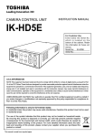
CAMERA CONTROL UNIT
INSTRUCTION MANUAL
IK-HD3D
For Customer Use
Enter below the Serial No.
which is located on the
bottom of the cabinet. Retain
this information for future reference.
Model No.: IK-HD3D
Serial No.:
U.S.A INFORMATION
This equipment has been tested and found to comply with the limits for a Class A digital device, pursuant to Part 15 of the FCC Rules. These limits are designed to provide reasonable protection against
harmful interference when the equipment is operated in a commercial environment. This equipment
generates, uses, and can radiate radio frequency energy and, if not installed and used in accordance
with the instruction manual, may cause harmful interference to radio communications. Operation of this
equipment in a residential area is likely to cause harmful interference in which case the user will be
required to correct the interference at his own expense.
USER-INSTALLER CAUTION: Your authority to operate this FCC verified equipment could be voided if
you make changes or modifications not expressly approved by the party responsible for compliance to
Part 15 of the FCC Rules.
Following information is only for EU-member states:
In residential areas this product may cause radio interference, therefore this product must
not be used in residential areas.
The use of the symbol indicates that this product may not be treated as household waste.
By ensuring this product is disposed of correctly, you will help prevent potential negative
consequences for the environment and human health, which could otherwise be caused by
inappropriate waste handling of this product. For more detailed information about the takeback and recycling of this product, please contact your supplier where you purchased the
product or consult.
This manual is made from recycled paper.
SAFETY PRECAUTIONS
Safety icons
This manual contains safety instructions that must be observed in order to avoid potential
hazards that could result in personal injuries, damage to your equipment, or loss of data.
These safety cautions have been classified according to the seriousness of the risk, and the
icons highlight these instructions as follows:
Indicates a potentially hazardous situation which, if not avoided, could result in
death or serious injury.
Indicates a potentially hazardous situation which, if not avoided, may result in
minor or moderate injury.
Indicates a potentially hazardous situation which, if not avoided, may result in
property damage.
Stop operation immediately if any abnormality or defect occurs.
Use during an abnormal condition; such as emitting smoke, burning odors,
damage from dropping, invasion of foreign objects, etc. may result in fire and/or
electric shock. Immediately disconnect the power source and contact your dealer.
Avoid installing in a shower room or a bathroom.
This may result in fire and/or electric shock.
Do not operate in places where the product may get wet.
This may result in fire and/or electric shock.
Do not repair, disassemble and/or modify by yourself.
This may result in fire and/or electric shock. Be always sure to contact your
dealer for internal repair, check and cleaning of the product.
Use the specified power supply.
Otherwise, fire or electrical shock may occur.
Do not place anything on top of the unit.
Foreign materials, such as metals or liquids into the product may result in fire
and/or electrical shock.
Do not put the product on an unstable, slanted on vibrating surface.
The product dropping or falling may cause serious injury.
Do not touch the product or any connection cables during a thunderstorm.
This may result in electrical shock.
2
Note the following instructions when installing.
s$ONOTCOVERTHEPRODUCTWITHANYMATERIAL
s$O NOT PLACE THE PRODUCT ON ANY CONFINED )NFLAMMABLE MATERIAL SUCH AS A
carpet or blanket.
s$ONOTPLACETHEPRODUCTINANARROWSPACEASTHISMAYCAUSEHEATTOBUILDUP
inside the product.
Failure to follow the above cautions may result in fire.
Do not place the product in direct sunshine and/or high temperature.
Temperature build up inside the product may result in fire.
Avoid placing in humid, smoky, vaporized or dusty places.
This may result in fire and/or electric shock.
Ask your dealer to perform a periodical check and internal cleaning
(approx. once every five years).
$USTINSIDETHEPRODUCTMAYRESULTINlRE&ORCHECKANDCLEANINGCOSTPLEASE
consult your dealer.
The following description is described the state that the suitable camera head is connected to this
camera control unit.
Do not point the lens directly at the sun and/or intensive light such as
direct sunlight, etc.
Focusing of the light may cause eye injury and/or fire.
Disclaimer
We disclaim any responsibility and shall not be responsible for any damages or losses incurred by
the user in any of the following cases:
1. Fire, earthquake or any other act of God; acts by third parties; misuse by the user, whether intentional or accidental; use under extreme operating conditions.
2. Malfunction or non-function resulting in indirect, additional or consequential damages, including
but not limited to loss of expected income and suspension of business activities.
3. Incorrect use not in compliance with instructions in this instruction manual.
4. Malfunctions resulting from misconnection to other equipment.
5. Repairs or modifications made by the user or caused to be made by the user and carried out by
an unauthorized third party.
Notwithstanding the foregoing, Toshiba America Information Systems, Inc.’s liabilities shall not, in
any circumstances, exceed the purchase price of the product.
Copyright and Right of Portrait
There may be a conflict with the Copyright Law and other laws when, the customer, uses, displays,
distributes, or exhibits an image picked up by the camera without permission from the copyright
holder. Please also note that transfer of an image or file covered by copyright is restricted to use
within the scope permitted by the Copyright Law. You are solely responsible for complying with all
applicable copyright laws.
3
Protection of Personal Information
Images taken by the camera that reveal the likeness of an individual person may be considered
personal information. To disclose, exhibit or transmit those images over the internet or otherwise,
consent from such individual person may be required. You are solely responsible to obtain such
consent.
Limitation of Usage
The product is not designed for any “critical applications.” “Critical applications” means life support
systems, exhaust or smoke extraction applications, medical applications, commercial aviation,
mass transit applications, military applications, homeland security applications, nuclear facilities or
systems or any other applications where product failure could lead to injury to persons or loss of life
or catastrophic property damages. Accordingly, We disclaim any and all liability arising out of the
use of the product in any critical applications.
TABLE OF CONTENTS
1. CAUTIONS ON USE AND INSTALLATION ...............................................................................................6
2. COMPONENTS ..........................................................................................................................................6
3. ITEMS CONTROLLED BY THE SCREEN DISPLAY .................................................................................7
4. NAMES AND FUNCTIONS ........................................................................................................................8
5. CONNECTION............................................................................................................................................9
5. 1 Standard Connection .........................................................................................................................9
5. 2 Cautions on Connection...................................................................................................................10
5. 3 Connector Pin Assignments.............................................................................................................10
6. OPERATION.............................................................................................................................................11
6. 1 Automatic Black Balance .................................................................................................................11
6. 2 White Balance ..................................................................................................................................11
6. 3 Scene File ........................................................................................................................................12
6. 4 Gain .................................................................................................................................................13
6. 5 Shading Correction ..........................................................................................................................14
6. 6 Switching of Video Signal Output .....................................................................................................14
7. MODE SETTING BY ON SCREEN DISPLAY ..........................................................................................15
7. 1 Using the Menus ..............................................................................................................................15
7. 2 Menus ..............................................................................................................................................16
( 1 ) SHUTTER (Electronic shutter).........................................................................................................16
(1. 1) Changing the setting in AUTO mode .....................................................................................17
(1. 2) Changing the setting in MANUAL mode ................................................................................19
(1. 3) Changing the setting in SS (Synchro. Scan) mode ................................................................19
( 2 ) GAIN (Video gain)............................................................................................................................20
(2. 1) Changing maximum gain in AUTO (AGC: Automatic gain control) mode ..............................20
(2. 2) Changing gain in MANUAL mode ..........................................................................................20
( 3 ) WHT BAL (White balance) ...............................................................................................................21
(3. 1) Changing the setting in AWB (Automatic White Balance) mode ...........................................21
(3. 2) Changing gain in MANUAL mode ..........................................................................................22
4
( 4 ) PROCESS1 .....................................................................................................................................23
(4. 1) Changing gamma correction ON/OFF ...................................................................................23
(4. 2) Changing gamma correction level .........................................................................................23
(4. 3) Changing black gamma correction level ................................................................................23
(4. 4) Changing pedestal .................................................................................................................24
(4. 5) Change of white clip ..............................................................................................................24
( 5 ) PROCESS2 .....................................................................................................................................25
(5. 1) Changing detail (outline) gain ................................................................................................25
(5. 2) Change of detail boost frequency ..........................................................................................25
(5. 3) Change of horizontal and vertical detail balance ...................................................................25
#HANGING$.2$IGITAL.OISE2EDUCTION ..............................................................................25
( 6 ) PROCESS3 .....................................................................................................................................26
(6. 1) Changing matrix color correction ON/OFF ...........................................................................26
(6. 2) Selection of matrix correction color........................................................................................26
(6. 3) Changing MATRIX setting......................................................................................................26
(6. 4) Change of chroma gain .........................................................................................................26
( 7 ) SYNC ...............................................................................................................................................27
(7. 1) INT screen .............................................................................................................................27
(7. 2) Changing EXT. setting ...........................................................................................................27
( 8 ) OPTION ...........................................................................................................................................28
(8. 1) Changing shading correction mode .......................................................................................28
(8. 2) Changing manual shading correction mode ..........................................................................28
(8. 3) Changing detail signal output ................................................................................................28
(8. 4) Change of vertical inversion setting .......................................................................................29
(8. 5) Change of horizontal inversion setting ...................................................................................29
(8. 6) Switching of inversion mode display ......................................................................................29
(8. 7) Change of binning setting ......................................................................................................29
(8. 8) Change of monitor receiver types ..........................................................................................29
(8. 9) Change of I/P mode ...............................................................................................................29
(8. 10) Changing RS-232C baud rate .............................................................................................29
( 9 ) Setting USER area ..........................................................................................................................30
( 10 ) Returning to factory settings ..........................................................................................................31
7. 3 External Sync ...................................................................................................................................31
7. 4 Synchro. Scan Operation .................................................................................................................31
8. BEFORE MAKING SERVICE CALL ........................................................................................................32
9. SPECIFICATIONS ....................................................................................................................................33
10. EXTERNAL APPEARANCE DIAGRAM ................................................................................................34
5
1. CAUTIONS ON USE AND INSTALLATION
s(ANDLINGTHEUNIT
$O NOT DROP JOLT OR VIBRATE AS THIS MAY RESULT IN
damage to the unit and may cause problems. Treat the
camera cables carefully to prevent cable problems,
such as breaks in the cable and loose connections.
The following descriptions are for a camera head
h)+($(vh)+(2(vCONNECTEDTOTHISCAMERACONTROL
unit.
s$ONOTSHOOTINTENSELIGHT
If strong light is entered, vertical stripes or traverse
bands may appear on the screen but this is not a
failure.
s)NSTALLTHECAMERAINALOCATIONFREEFROMNOISE
If the camera or the cables are located near power
utility lines or a TV, etc. undesirable noise may appear
on the screen. In such a case, try to change the
location of the camera or the cable wiring.
s-OIRE
A moire pattern is an interference pattern generated
when two repetitive line patterns overlap. This is not a
malfunction. Eliminating the repetitive line patterns, or
aligning the two patterns, will eliminate the moire.
s/PERATINGAMBIENTTEMPERATUREANDHUMIDITY
$ONOTUSETHECAMERAINPLACESWHERETEMPERATURE
and humidity exceed the specifications. Picture quality
will deteriorate and internal parts may be damaged.
s(ANDLINGOFTHECAMERAHEADANDPROTECTIONCAP
Keep the camera head and protection cap away from
children as they may pose a choking hazard. Because
the protection cap protects the image sensing plane
when the lens is removed from the camera head, do
not discard the protection cap.
Be particularly careful when using in places exposed
to direct sunlight. When shooting in hot environments,
depending on the conditions of the object and the
camera (for example when the gain is increased),
noise in the form of vertical strips or white dots may
occur. This is not a malfunction.
s7HENCLEANINGTHECAMERA
Unplug the power source before cleaning. Clean
WITH A SOFT DRY CLOTH ONLY $O NOT USE CHEMICALS OR
chemically treated cloths. Chemicals may damage
coatings and printed letters. When cleaning the lens,
use lens cleaning paper.
s7HENNOTUSINGTHECAMERAFOREXTENDEDPERIODS
of time.
Switch the control unit off and disconnect the power
supply.
s!VOIDUSINGORSTORINGTHECAMERAINTHEFOLLOWING
places:
Places filled with highly flammable and corrosive gas.
s)NSTALLATIONWITHOUTATRIPOD
Before installing the camera head, make sure that the
location can withstand the total weight of the camera
head.
If this is not the case, reinforce the area to prevent the
unit from dropping, which may result in damage to the
unit or personal injury.
Places near gasoline, benzene, or paint thinner.
Places subject to strong vibration.
Places containing chemicals (such as pesticides),
rubber or vinyl products for extended periods of time.
s4HISPRODUCTISFORINDOORUSEONLY
2. COMPONENTS
(1) Camera Control Unit ...................................................................................................................... 1
(2) Accessories
(a) Instruction manual .................................................................................................................. 1
6
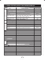
3. ITEMS CONTROLLED BY THE SCREEN DISPLAY
Electronic shutter
Item
Available selections
-/$%
AUTO level
AUTO peak/average
AUTO response speed
AUTO, MANUAL, SS
-100 – 0 – 100
00 : 10 – 05 : 05 – 10 : 00
1 – 10 – 20
02%3%4!02%3%4"02%3%4#02%3%4$02%3%4%
USER (USER area is possible to set in 64 zones)
1/200s, 1/250s, 1/300s, 1/350s, 1/400s, 1/450s, 1/500s,
1/550s, 1/600s, 1/700s, 1/800s, 1/900s, 1/1000s,
1/1200s, 1/1500s, 1/2000s, 1/4000s, OFF
OFF, 1/100s, 1/125s, 1/250s, 1/500s, 1/1000s, 1/2000s,
1/3000s, 1/4000s, 1/5000s, 1/10000s
1/1125H – 1122/1125H, OFF
AUTO, MANUAL, OFF
0dB to 20dB
-3dB to 20dB
AWB, MANUAL
3200K, 5600K
-10 – 0 – 10
-10 – 0 – 10
02%3%4!02%3%4"02%3%4#02%3%4$02%3%4%
USER (USER area is possible to set in 64 zones)
-100 – 0 – 100
-100 – 0 – 100
ON, OFF
-10 – 0 – 10
LOW, NORMAL, HIGH
-200 – 0 – 200
-100 – 0 – 100
-100 – 0 – 100
100% − 109%
0 − 10 − 31
1 − 10 − 16
8/16 − 16/16 − 24/16 (ratio of V/H)
ON, OFF
ON, OFF
R, R-Ye, Ye, Ye-G, G, G-Cy, Cy, Cy-B, B, B-Mg, Mg, Mg-R
-15 – 0 – 15
-15 – 0 – 15
-31 − 0 − 31
-650 – 0 – 650
SET, MANUAL, OFF
-128 – 0 – 127
ON, OFF
ON, OFF
ON, OFF
ON, OFF
ON, OFF
PC, TV
1080p, 1080i
9600bps, 19200bps
AUTO area
Maximum AUTO shutter
speed
MANUAL shutter speed
Gain
White balance
Syncro. scan
-/$%
AUTO maximum gain
MANUAL gain
-/$%
Color temperature
AWB R PAINT
AWB B PAINT
AWB area
Matrix
MANUAL R GAIN
MANUAL B GAIN
Gamma correction
Gamma correction level
Black gamma correction level
Master pedestal
Red pedestal
Blue pedestal
White clip
$ETAILGAIN
$ETAILBOOSTFREQUENCY
HV balance
$IGITALNOISEREDUCTION$.2
Correction ON/OFF
Selection of correction color
Phase
Gain
Chroma gain
Ext. Sync
H phase adjustment
Shading correction mode
Manual shading correction
$ETAILSIGNALOUTPUT
Vertical inversion
Horizontal inversion
Inversion mode display switch
Binning
Monitor
I/P mode
RS-232C baud rate
7
Preset value
(Factory setting)
MANUAL
0
05 : 05
10
PRESET A
OFF
OFF
OFF
OFF
20dB
0dB
AWB
3200K
0
0
PRESET A
0
0
ON
0
NORMAL
0
0
0
109%
10
10
16/16
OFF
ON
R
0
0
0
0
OFF
0
OFF
OFF
OFF
OFF
OFF
PC
1080p
9600bps
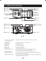
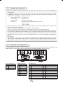
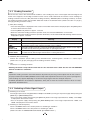
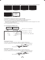
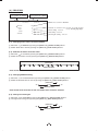
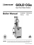
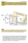
4. NAMES AND FUNCTIONS
FILE button
DISP button
POWER switch
MENU UP
(SHD) button
POWER LED
DATA UP
(AWB) button
Camera cable
for “IK-HD3H” or
“IK-HR3H” terminal
DATA DOWN
(ABB) button
GAIN button
MENU DOWN
button
PAGE button
[Front]
FORMAT switch
EXT. SYNC terminal
KEY LOCK switch
SYNC OUT terminal
DC IN 12V terminal
1
2
4
3
1 2 3 4 5
1 2 3 4 5 6 7 8
9 10 11 12 13 14 15 16
17 18 19 20 21 22 23 24
6 7 8 9
REMOTE terminal
DVI-D terminal
[Rear]
/#AMERACABLEFORh)+($(v
or “IK-HR3H” terminal
7HERETHECAMERACABLEFORh)+($(vORh)+(2(vISCONNECTED
00/7%2,%$
Illuminates to indicate the unit is powered on.
1 POWER switch
Turns power on or off.
2 FILE button
To switch the scene files.
3 GAIN button
To change the gain mode.
4$)30BUTTON
Changes the display mode.
5 PAGE button
To switch and select menus.
6-%.5503($BUTTON
To select the function to be confirmed or changed on the menu.
(Also used when performing auto shading correction.)
7-%.5$/7.BUTTON
To select the function to be confirmed or changed on the menu.
8$!4!50!7"BUTTON
4OCHANGETHEVALUEOFTHEFUNCTIONSELECTEDBYTHE-%.550$/7.BUTTON
(Also used when performing an AWB.)
9$!4!$/7.!""BUTTON
4OCHANGETHEVALUEOFTHEFUNCTIONSELECTEDBYTHE-%.550$/7.BUTTON
(Also used when performing an ABB.)
8
:$#).6TERMINAL
!CCEPTSA$#POWERINPUT6
; REMOTE terminal
To connect to a RS-232C device for remote control function.
< EXT. SYNC terminal
Used when the camera output signal is synchronized to an external signal.
(BNC connector)
= SYNC OUT terminal
Output terminal for synchronization signal. (BNC connector)
>$6)$TERMINAL
$6)$OUTPUTTERMINAL
? KEY LOCK switch
Enables/disables buttons 2to 9.
@ FORMAT switch
Switches between 59.94Hz and 50Hz.
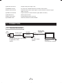
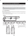
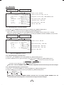
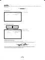
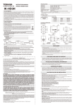
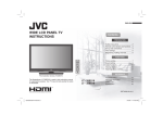
5. CONNECTION
5. 1 Standard Connection
Lens
(option)
Camera
Head
Camera Cable
for IK-HD3D
䠄option䠅
IK-HD3D
DVI-D
Camera
Control unit
IK-HD3H or
IK-HR3H (Scheduled to be available
in September, 2013)
(option)
DVI-D Cable
(Commercially
available)
DC IN 12V
DC power supply
(option)
9
DVI monitor
DVI-D TV
(Commercially available)
5. 2 Cautions on Connection
s7HENCONNECTINGTHECAMERACABLESBESURETOTURNOFFTHECAMERACONTROLUNITANDANYOTHEREQUIPMENT
connected to it.
s&OR$#POWERSUPPLYCONNECTINGTO$#).6TERMINALUSECLASS))$#POWERSUPPLYAPPROVEDACCORDING
to EN60950-1 in Europe. or use UL listed and/or CSA approved ungrounded type AC adaptor with the
specifications described below in U.S.A. or Canada.
0OWERSUPPLYVOLTAGE
Current rating
Ripple voltage
Connector
6$#
: More than 1.5A
: Less than 50 mV (p–p)
: HR10A–7P–4S by HIROSE electronics Co. Ltd
Pins 1, 2 : 12V
0INS'.$
s)FTHESECURINGSCREWONTHECONNECTOROFTHECAMERACABLELOOSENSNOISEMAYAPPEARONTHESCREEN"ESURE
to tighten the connector completely.
s/NLYUSETHESPECIlCOPTIONALCAMERAHEADSWITHTHISCAMERACONTROLLER
The use of any other camera heads may cause damage to the control unit and camera head.
s4HEVIDEOSIGNALOUTPUTOFTHISCAMERACONTROLUNITHASNOFUNCTIONFORAUTOMATICALLYSELECTINGOUTPUTACCORDING
TOTHERESOLUTIONOF$6)MONITOR464HEREFOREBESURETOSWITCHTHEOUTPUTMODEOFTHISCAMERACONTROLUNIT
according to the monitor’s resolution as no image will be displayed on the monitor if the camera output mode
and the monitor input mode do not match. For switching, refer to the item 6.6 “Switching of Video Signal
Output”.
s$6)STANDARD
4HE$6)DIGITALVISUALINTERFACEISTHECONNECTIONINTERFACESTANDARDFORmATPANELDISPLAY&0$SUCHAS,#$
DISPLAYS4HEREARETHREETYPESOF$6)CONNECTORSNAMELY$6))FORBOTHDIGITALANALOG$6)$EXCLUSIVELYFOR
DIGITALAND$6)!EXCLUSIVELYFORANALOG5SEACOMMERCIALLYAVAILABLE$6)$CABLEFORTHISCAMERACONTROLUNIT
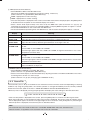
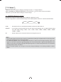
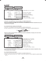
5. 3 Connector Pin Assignments
/N THE REAR PANEL OF THE CAMERA CONTROL UNIT $# ). 6 TERMINAL USED FOR BASIC CONNECTION AND 2%-/4% %84
39.#39.#/54AND$6)$TERMINALAREPROVIDED#ONNECTCABLESDEPENDINGONYOURNECESSITY
1
2
4
3
1 2 3 4 5
1 2 3 4 5 6 7 8
9 10 11 12 13 14 15 16
17 18 19 20 21 22 23 24
6 7 8 9
$#).6TERMINAL
1
+12V
2
+12V
3
'.$
4
'.$
REMOTE terminal
1
NC
2
48$
3
28$
4
NC
5
'.$
6
NC
7
NC
8
NC
9
NC
$6)$TERMINAL
1
$ATA
2
$ATA
3
$ATA3HIELD'.$
4
NC
5
NC
6
NC
7
NC
8
NC
9
$ATA
10 $ATA
11 $ATA3HIELD'.$
12 NC
10
13
14
15
16
17
18
19
20
21
22
23
24
NC
+5V
'.$
(OT0LUG$ETECT
$ATA
$ATA
$ATA3HIELD'.$
NC
NC
#LOCK3HIELD'.$
Clock+
Clock-
6. OPERATION
A camera head needs to be connected to this camera control unit from this section on.
/ Refer to the item “5. CONNECTION”, connect the equipment correctly.
0 Turn on the connected equipment and the camera.
1 When using the camera for the first time and when replacing the camera head, be sure to perform the ABB
adjustment, refer to the item “6.1 Automatic Black Balance”.
2 Aim the lens at the object, adjust the lens iris adjustment, focus adjustment, etc.
3 Refer to the item “6.2 White Balance”, make the adjustment.
4 2EFERTOTHEITEMSh3CENE&ILE'AIN-/$%3%44).'"94(%/.3#2%%.$)30,!9vSELECTTHE
necessary items.
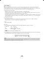
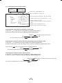
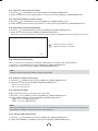
6. 1 Automatic Black Balance
Black balance adjustment is necessary to get the correct black picture level.
s#LOSETHELENSIRIS
s)FTHECOLORBARPATTERNISDISPLAYEDONTHESCREENORIFTHEINDEXMENUMENUISDISPLAYEDPRESSTHE;$)30=BUTTONTO
disable the color bar pattern or the character display.
s(OLDTHE;$!4!$/7.=BUTTONFORAPPROXSECOND
s7HENTHEBLACKBALANCEADJUSTMENTOPERATIONSTARTSTHECHARACTER!""BLINKSONTHESCREEN
s7HENTHEBLACKBALANCEADJUSTMENTOPERATIONlNISHESTHECHARACTER!""STOPSBLINKINGANDTHERESULTAPPEARSFOR
approx. 1 second.
Display
ABB OK
ABB NG
CLOSE LENS
ABB NG
Meaning
Automatic black balance adjustment finished correctly.
Automatic black balance adjustment cannot be performed because the lens iris is open. Close
the lens iris.
Automatic black balance adjustment cannot be performed.
Operate the automatic black balance again.
6. 2 7HITE"ALANCE
For white balance adjustment of this unit, AWB (Automatic White Balance) and MANUAL (Manual white balance)
ADJUSTMENTSAREPROVIDED2EFERTOTHEITEMSh7(4"!,7HITE"ALANCE-/$%3%44).'"94(%/.
3#2%%.$)30,!9vSELECTTHEDESIREDMODE
!7"
!UTOMATIC7HITE"ALANCE
Outline
MANUAL
-ANUAL7HITE"ALANCE
Adjust white balance by displaying a white object Adjust the white balance manually using the WHT
inside the area set by AWB menu and holding the BAL menu while shooting a white object.
;$!4!50=BUTTONFORAPPROXSECOND
Features Automatically adjusts red and blue balance based White balance can be set manually.
on green for the object in the designated area .
Note
When no white object exits in the designated area Adjustment is performed by confirming with a
or lighting is too blight or too dark, AWB NG is monitor etc.
displayed and automatic white balance adjustment
can not be performed.
11
/ AWB (Automatic white balance)
s3ETTHE-/$%TO!7"ONTHE7(4"!,MENU
Perform the C.TEMP (color temperature conversion) setting, if necessary.
(Refer to the item “7.2 (3) WHT BAL (White Balance)”.)
3200K : Appropriate for indoor shooting.
5600K : Appropriate for outdoor shooting.
s)FTHECOLORBARPATTERNISDISPLAYEDONTHESCREENORIFTHEINDEXMENUMENUISDISPLAYEDPRESSTHE;$)30=BUTTON
to disable the color bar pattern or the character display on the menu.
s3HOOT A KNOWN WHITE OBJECT ENTIRELY IN THE AREA SET BY THE !7" MENU REFER TO THE ITEM h D
#ONlRMINGTHECONTENTSOFTHEZONEAREASELECTEDBY!7"vANDPUSH;$!4!50=BUTTONFORAPPROXSECOND
s4HECHARACTER!7"BLINKSONTHESCREENWHENTHE!7"STARTS
s4HECHARACTER!7"STOPSBLINKINGWHENTHE!7"lNISHESANDTHERESULTISDISPLAYEDFORAPPROXSECOND
Display
!7"/+
!7".'
,%6%,,/7
!7".'
LEVEL HIGH
!7".'
#4%-0,/7
!7".'
C. TEMP HIGH
!7".'
Meaning
Automatic white balance adjustment finished correctly.
Automatic white balance adjustment cannot be performed because the video level is too low.
Adjust the video level by increasing the illumination or opening the lens iris.
Automatic white balance adjustment cannot be performed because the video level is too high.
Adjust the video level by decreasing the illumination or closing the lens iris.
Automatic white balance adjustment cannot be performed because the color temperature is
too low.
If the C.TEMP is set to 5600K, set to 3200K.
If the message appears with the C.TEMP set to 3200K, change the illumination or use a color
temperature conversion filter.
Automatic white balance adjustment cannot be performed because the color temperature is
too high.
If the C.TEMP is set to 3200K, set to 5600K.
If the message appears with the C.TEMP set to 5600K, change the illumination or use the color
temperature convearsion filter.
Automatic white balance adjustment cannot be performed for other reasons. Such as no white
area is included in an object, etc.
0 MANUAL (Manual white balance)
s3ETTHE-/$%TO-!.5!,ONTHE7(4"!,MENU
(Refer to the item “7.2 (3) WHT BAL (White Balance)”.)
s3HOOTAKNOWNWHITEOBJECTSETTHEWHITEBALANCEBYADJUSTINGTHELEVELSOF2'!).AND"'!).ONTHEMENU
confirming with a monitor or a vector scope.
(Refer to the item “7.2 (3) (3.2) Changing gain in MANUAL mode”.)
6. 3 Scene File
&IVESCENElLES!"#$%AREAVAILABLEASUSERMEMORIESFORTHISUNIT4HESEARECHOSENDEPENDINGONSHOOTING
CONDITIONS "Y USING THE ;&),%= BUTTON THE CAMERA OPERATION IS CHANGED IMMEDIATELY FROM THE CURRENTLY SELECTED
3CENE&ILETOTHENEXT2EFERTOTHEITEMh-/$%3%44).'"94(%/.3#2%%.$)30,!9v
s7HILEANYMENUISDISPLAYEDPRESSINGTHE;&),%=BUTTONWILLDISPLAYTHEMENUSETTINGSFORTHENEXT3CENE&ILE
FILE A 䊲 FILE B 䊲 FILE C 䊲 FILE D 䊲 FILE E
s)FTHECOLORBARPATTERNISDISPLAYEDONTHESCREENPRESSTHE;$)30=BUTTONTOSWITCHTOTHEVIDEOSIGNALSCREEN
s7HENTHE;&),%=BUTTONISPRESSEDWHILETHEVIDEOSIGNALSCREENISDISPLAYEDTHECURRENTSCENElLESELECTIONATTHAT
TIMEISDISPLAYEDFORAPPROXSECONDSINTHEUPPERRIGHTCORNEROFTHESCREEN)FTHE;&),%=BUTTONISPRESSEDAGAIN
while the position is displayed, the scene file cycles as described above.
Note:
4HESCENElLEDOESNOTINCLUDETHEDATASETINh)0-/$%vh"!5$2!4%vWITHINTHEh/04)/.vMENU
Refer to the item “7.2 (8) Menus” for the contents that can be set in OPTION.
12
6. 4 Gain
When the image is dark even if the lens iris is open, change the gain (video gain) to get the desired video level.
For gain adjustment of the unit, AUTO (Automatic gain control), MANUAL (Manual gain control), OFF (0 dB) modes
are provided. Select the mode on the GAIN menu. (Refer to the item “7.2 (2) GAIN (Video gain)”.)
/ AUTO (Automatic gain control)
When the output is low, gain is automatically adjusted to a suitable video level.
The maximum value of gain is 20dB, and can be set from 0 to 18dB in 1dB steps. (Refer to the item “7.2 (2) (2.1)
Changing the maximum gain in AUTO (Automatic gain control) mode”.)
Video level (LEVEL), peak average value ratio (PEAK/AVE), measurement light area (AREA), and response
SPEED30%%$ARELINKEDTOTHESETTINGONTHEAUTOMATICSHUTTER2EFERTOTHEITEMh#HANGINGTHE
setting in AUTO mode”.)
0 MANUAL (Manual gain)
Gain adjustment is performed on the GAIN menu. The adjustment range is from -3 to 20dB in 1dB steps.
(Refer to the item “7.2 (2) (2.2) Changing gain in MANUAL mode”.)
1 OFF
Gain is fixed at 0 dB.
Gain button
/ )FTHE;'!).=BUTTONISPRESSEDTHECURRENTGAINSETTINGISDISPLAYEDFORAPPROXSECONDS
GAIN menu
:
OFF → GAIN OFF
SS
:
AUTO → GAIN AUTO
AUTO
:
MANUAL
“
dB → GAIN dB
” shows the setting gain in MANUAL mode.
0 )FTHE;'!).=BUTTONISPRESSEDAGAINWHILETHECURRENTSETTINGMODEISDISPLAYEDTHEGAINMODECANBECHANGED
GAIN of MAX GAIN in AUTO mode and MANUAL mode can not be changed.
OFF 䊲 AUTO 䊲 MANUAL
Note:
White, red, green, or blue dots may occur when the gain is increased. This is not a malfunction, just certain
characteristics of the CMOS sensor becoming more visible.
13
6. 5 Shading Correction
$UETOTHELENSUSEDORTHEENVIRONMENTALCONDITIONCOLORSHADINGMAYOCCURATTHEUPPERANDLOWEREDGEOFTHE
screen. If this happens, the shading correction function can be used to decrease the amount of color shading. For
shading correction of the unit, SET (Automatic shading correction), MANUAL (Manual shading correction), and OFF
(no shading correction) modes are provided. Select the mode on the OPTION menu. (Refer to the item “7.2 (8) (8.1)
Changing shading correction mode”.)
/ SET (Auto shading)
s)FTHECOLORBARPATTERNISDISPLAYEDONTHESCREENORIFTHEINDEXMENUMENUISDISPLAYEDPRESSTHE;$)30=BUTTON
to remove them from the screen.
s0USHTHE;-%.550=BUTTONFORAPPROXSECOND
s7HENTHEAUTOMATICSHADINGCORRECTIONOPERATIONSTARTSTHECHARACTER3($BLINKSONTHESCREEN
s7HENTHEAUTOMATICSHADINGCORRECTIONOPERATIONTERMINATESTHECHARACTER3($ENDSBLINKINGANDTHERESULTIS
displayed for approx. 1 second.
Display
SHD OK
SHD OK
LIMIT
SHD NG
,%6%,,/7
SHD NG
LEVEL HIGH
Meaning
Automatic shading correction operation finished correctly.
Automatic shading correction operation finished, however, the correction necessary exceeds
the camera’s range so the maximum possible value is applied.
Automatic shading correction cannot be performed because the video level is too low. Adjust
the video level by increasing the illumination or opening the lens iris.
Automatic shading correction cannot be performed because the video level is too high. Adjust
the video level by decreasing the illumination or closing the lens iris.
0 MANUAL (Manual Shading)
Perform the correction amount setting on the OPTION menu, confirming with a monitor or a vector scope.
(Refer to the “7.2 (8) (8.2) Changing manual shading correction mode”.)
1 OFF
The status is no shading correction.
* Shading correction is only effective when the lens iris and zoom ratio is fixed. Use the unit with SHADING
OFF for variable lens conditions.
Note:
Implement shading correction after white balance adjustment by shooting a white object that fills the screen in
THEPROPERVIDEOLEVEL)+($(#-/3CAMERAHEADNEEDSADJUSTMENTBECAUSEITUSESPRISMTOSPLITLIGHTAND
white shading may appear depending on the entrance angle against the lens exit pupil and prism.
IK-HR3H (Scheduled to be available in September, 2013) will not have this function because it does not need
adjustment described above.
6. 6 Switching of Video Signal Output
/ Switching of I/P modes
The image output can be changed between “1080p” and “1080i” by turning on the power supply while pushing the
;$!4!50=OR;$!4!$/7.=BUTTON
s4URNONTHEPOWERSUPPLYWHILEPUSHINGTHE;$!4!50=BUTTON4HEIMAGEOUTPUTBECOMEShPvANDhPv
is displayed on the monitor screen.
s4URN ON THE POWER SUPPLY WHILE PUSHING THE ;$!4! $/7.= BUTTON4HE IMAGE OUTPUT BECOMEShIv AND
“1080i” is displayed on the monitor screen.
0 Switching of vertical frequency
Turn the FORMAT switch to the “59.94” position for switching to “59.94Hz”.
Turn the FORMAT switch to the “50” position for switching to “50Hz”.
2EFERTOTHEITEMh.!-%3!.$&5.#4)/.3@ FORMAT switch”.)
14
7. MODE SETTING BY ON SCREEN DISPLAY
Various settings can be controlled on the unit by using the on screen menu displayed on the monitor. The contents
ONCESETAREMEMORIZEDINTHESCENElLES!"#$%SELECTEDSOIFTHEPOWERTURNSOFFITISUNNECESSARYTOSET
again when using the unit next time. When the setting is performed, select the menu of the item to be set.
Note:
$ISPLAYEDTEXTSWHILEPRESSINGTHESCREENMENUAUTOWHITEBALANCE!7"OROTHERMENUSAREOUTPUTTOTHE
taken videos. These texts on the videos are not removable after the videos are recorded. Therefore, be careful
when you operate the screen menu, AWB and other menus.
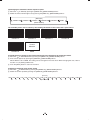
7. 1 Using the Menus
When the power turns on, the normal screen showing only the video signal appears. Change the output to each
SCREENVIDEOSIGNALOUTPUTCOLORBARSCREEN)NDEXMENUMENUSANDAREAMENUBYUSINGTHE;$)30=;0!'%=
;-%.550=AND;-%.5$/7.=BUTTONS
!MENUISSELECTEDWHENPUSHINGTHE;0!'%=BUTTONAFTERMOVINGTHEh vTHESCREENBYTHE;-%.550=;-%.5
$/7.=BUTTONWHILETHE)NDEXMENUISDISPLAYED
POWER SW
ON
Video signal output
Color bar screen
DISP
DISP
Index menu
DISP
PAGE
DISP
PAGE
PAGE
Menus
PAGE
1.SHUTTER
2.GAIN
3.WHT BAL
PAGE
AUTO
MANUAL
SS
PAGE
AUTO
4.PROCESS1
PAGE
GAMMA
ON
AWB
MANUAL
5.PROCESS2
PAGE
8.OPTION
7.SYNC
PAGE
PAGE
INT
SHADING
OFF
EXT.
SET
MANUAL
OFF
DISP
MATRIX
ON
MATRIX
OFF
GAMMA
OFF
MANUAL
6.PROCESS3
PAGE
DATA
UP/DOWN
Area menu
DISP
DATA
UP/DOWN
Area menu
A
A
B
B
C
C
D
D
E
E
USER
USER
15
The screen is changed to the area screen by
selecting AUTO in the 1.SHUTTER menu and
AWB in the 3.WHT BAL menu in the setting
screen For more details, refer to the item "7.2
Menus".
7. 2 Menus
s3ELECTTHEMENUTOCHANGETHESETTINGBYREFERRINGTOTHEITEMh5SINGTHE-ENUSv
s7HENTHE;-%.550=;-%.5$/7.=BUTTONSAREPUSHEDTHEh ” on the screen moves up and down.
Move the “ ” to the item whose setting you wish to change.
( 1 ) SHUTTER (Electronic shutter)
The electronic shutter has three modes; AUTO, MANUAL, SS(Synchro. Scan).
0RESSTHEh0AGEvBUTTONTOENTERTHE3HUTTER0AGE5SETHEh$ATA5P$OWNvBUTTONSTOSELECTTHE3HUTTER-ODE
AUTO
MANUAL
SS
AUTO
:
The exposure time is controlled automatically to obtain the video level set.
MANUAL
:
It is possible to select the exposure time from eleven speed settings; OFF (at 1/60s: 59.94Hz setting
and 1/50s: 50Hz setting), 1/100s, 1/125s, 1/250s, 1/500s, 1/1000s, 1/2000s, 1/3000s, 1/4000s,
1/5000s, 1/10000s.
SS
:
Shutter speed can be set by the horizontal scanning time (1H) unit.
Notes:
s)FTHESHUTTERSPEEDISINCREASEDTHESENSITIVITYISDECREASEDACCORDINGTOTHESPEED&LICKERMAYBELARGEUNDER
discharge lamp lighting such as fluorescent tubes.
s)F A FASTMOVING OBJECT IS SHOT ITS IMAGE MAY BE DISTORTED OR BLURRED (ORIZONTAL LIGHTANDDARK STRIPES MAY
appear on the screen under discharge lamp lighting such as fluorescent tubes. A light and dark difference may
appear on the screen according to the light emitting timing of flash or strobe. These phenomena are caused due
to rolling shutter system, not failures.
s7HEN THE SHUTTER SPEED IS SET TO HIGH THE HUE MAY CHANGE ACCORDING TO THE SHOOTING CONDITIONS AND THE
object.
16
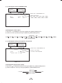
(1. 1) Changing the setting in AUTO mode
Move up and down
by pushing
MENU UP, DOWN
Select the desired
value by pushing
DATA UP, DOWN
Shutter mode
AUTO, MANUAL, SS
Video level adjustment
--
1
SHUTTER --
-100 to 100
(FILE A)
Peak and average ratio adjustment
MODE
LEVEL
PEAK AVE
SPEED
AREA
AREA DISPLAY
MAX SHUT
AUTO
0
05 05
10
PRESET A
OFF
OFF
00
10 to 10
Automatic shutter response speed adjustment
00
1 to 20
Automatic shutter area selection
PRESET A, PRESET B, PRESET C, PRESET D, PRESET E,
USER
Automatic shutter area display selection
Automatic shutter maximum speed setting
<MODE = AUTO>
(a) Changing the video level in the automatic shutter mode
/I Move the “ vTO,%6%,BYPUSHINGTHE;-%.550=;-%.5$/7.=BUTTONS
0I 3ELECTTHEVIDEOLEVELBYPUSHINGTHE;$!4!50=;$!4!$/7.=BUTTONS
;$!4!50=
The value increases by pushing
0
-100
100
;$!4!$/7.=
The value decreases by pushing
(b) Changing the automatic shutter detection (ratio between peak and average value)
/I Move the “ vTO0%!+!6%BYPUSHINGTHE;-%.550=;-%.5$/7.=BUTTONS
0I 3ELECTTHERATIOBETWEENPEAKANDAVERAGEVALUEBYPUSHINGTHE;$!4!50=;$!4!$/7.=BUTTONS
(Peak: Average)
4HEPEAKVALUEINCREASESBYPUSHING;$!4!50=
05:05
00:05
The peak value decreases by pushing
10:00
;$!4!$/7.=
(c) Changing the automatic shutter response speed
/I Move the “ vTO30%%$BYPUSHINGTHE;-%.550=;-%.5$/7.=BUTTONS
0I 3ELECTTHERESPONSESPEEDBYPUSHINGTHE;$!4!50=;$!4!$/7.=BUTTONS
;$!4!50=
1
The response speed becomes slower by pushing
The response speed becomes faster by pushing
10
;$!4!$/7.=
17
20
(d) Changing the automatic shutter response speed
/I Move the “ vTO!2%!BYPUSHINGTHE;-%.550=;-%.5$/7.=BUTTONS
0I 3ELECTTHEMEASUREMENTLIGHTAREABYPUSHINGTHE;$!4!50=;$!4!$/7.=BUTTONS
[DATA UP]
PRESET A
PRESET B
PRESET C
PRESET D
[DATA DOWN]
PRESET E
USER
The available picture area is shown by the shading correction on the screen that is parted in 64.
PRESET A
PRESET B
PRESET C
PRESET D
Custom
Selection
PRESET E
USER
(e) Confirming the contents of the measurement light area selected by the automatic shutter
/I Move the “ vTO!2%!$)30,!9BYPUSHINGTHE;-%.550=;-%.5$/7.=BUTTONS
0I !REASCREENAPPEARSBYPUSHINGTHE;$!4!50=;$!4!$/7.=BUTTONS
When AREA is set to USER, the setting can be changed on the area menu. When changing the area, refer to
the item “7.2 (8) Setting USER area”.
1I 0USHTHE;$)30=BUTTONTORETURNTOTHEMENU
(f) Setting of maximum auto shutter speed
/I Move the “ vTO-!83(54BYPUSHINGTHE;-%.550=;-%.5$/7.=BUTTONS
0I 3ELECTTHESHUTTERSPEEDBYPUSHINGTHE;$!4!50=;$!4!$/7.=BUTTONS
[DATA UP]
1/200s 1/250s 1/300s 1/350s 1/400s 1/450s 1/500s 1/550s 1/600s 1/700s 1/800s 1/900s 1/1000s 1/1200s 1/1500s 1/2000s 1/4000s OFF
[DATA DOWN]
18
(1. 2) Changing the setting in MANUAL mode
Move up and down
by pushing
MENU UP, DOWN
Select the desired
value by pushing
DATA UP, DOWN
Shutter mode
--
1
SHUTTER --
MODE
MANUAL
AUTO, MANUAL, SS
(FILE A)
Shutter speed setting
OFF, 1/100s, 1/125s, 1/250s, 1/500s, 1/1000s,
1/2000s, 1/3000s, 1/4000s, 1/5000s, 1/10000s
MANUAL
OFF
<MODE = MANUAL>
(a) Changing the shutter speed
/I Move the “ vTO-!.5!,BYPUSHINGTHE;-%.550=;-%.5$/7.=BUTTONS
0I 3ELECTTHESHUTTERSPEEDBYPUSHINGTHE;$!4!50=;$!4!$/7.=BUTTONS
OFF
1/100s
1/125s
1/250s
1/500s
[DATA UP]
1/1000s 1/2000s
1/3000s
1/4000s
[DATA DOWN]
(1. 3) Changing the setting in SS (Synchro. Scan) mode
Move up and down
by pushing
MENU UP, DOWN
Select the desired
value by pushing
DATA UP, DOWN
Shutter mode
--
1
SHUTTER --
MODE
SYNCHRO SCAN
AUTO, MANUAL, SS
(FILE A)
SS
OFF
Synchro. scan setting
1/1125H to 1122/1125H, OFF
<MODE = SS>
(a) Changing the Synchro. Scan setting
/I Move the “ vTO39.#(2/3#!.BYPUSHINGTHE;-%.550=;-%.5$/7.=BUTTONS
0I 3ELECTTHE3YNCHRO3CANBYPUSHINGTHE;$!4!50=;$!4!$/7.=BUTTONS
;$!4!50=
1/1125H
1122/1125H
;$!4!$/7.=
19
OFF
1/5000s
1/10000s
( 2 ) GAIN (Video gain)
GAIN has three modes; AUTO, MANUAL, OFF.
Move the “ vTO-/$%PUSHTHE;$!4!50=;$!4!$/7.=ANDSELECTONEOFTHETHREEMODES!54/-!.5!,
OFF. In the OFF mode, gain is fixed to 0dB.
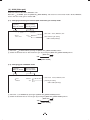
(2. 1) Changing maximum gain in AUTO (AGC: Automatic gain control) mode
Move up and down
by pushing
MENU UP, DOWN
--
2
GAIN
Select the desired
value by pushing
DATA UP, DOWN
--
(FILE A)
Gain mode
MODE
MAX GAIN
AUTO
20dB
AUTO, MANUAL, OFF
AGC maximum gain setting
0dB to 20dB (1dB step)
/I Move the “ vTO-!8'!).BYPUSHINGTHE;-%.550=;-%.5$/7.=BUTTONS
0I 3ELECTTHEDESIREDVALUEOF!'#MAXIMUMGAINBYPUSHINGTHE;$!4!50=;$!4!$/7.=BUTTONS
;$!4!50=
0dB
20dB
;$!4!$/7.=
(2. 2) Changing gain in MANUAL mode
Move up and down
by pushing
MENU UP, DOWN
--
2
GAIN
Select the desired
value by pushing
DATA UP, DOWN
--
(FILE A)
Gain mode
MODE
MANUAL
MANUAL
0dB
AUTO, MANUAL, OFF
Manual gain setting
-3dB to 20dB (1dB step)
/I Move the “ vTO-!.5!,BYPUSHINGTHE;-%.550=;-%.5$/7.=BUTTONS
0I 3ELECTTHEDESIREDVALUEOFMANUALGAINBYPUSHINGTHE;$!4!50=;$!4!$/7.=BUTTONS
;$!4!50=
-3dB
20dB
;$!4!$/7.=
20
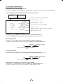
( 3 ) 7(4"!,7HITEBALANCE
The WHT BAL has two modes; AWB, MANUAL.
Move the “ vTO-/$%PUSHTHE;$!4!50=;$!4!$/7.=ANDSELECTONEOFTHETWOMODES!7"-!.5!,
(3. 1) #HANGINGTHESETTINGIN!7"!UTOMATIC7HITE"ALANCEMODE
Move up and down
by pushing
MENU UP, DOWN
Select the desired
value by pushing
DATA UP, DOWN
White balance mode setting
--
3
WHT BAL --
MODE
R PAINT
B PAINT
C TEMP
AREA
AREA DISPLAY
AWB, MANUAL
R PAINT adjustment
-10 to 10
B PAINT adjustment
-10 to 10
(FILE A)
AWB
0
0
3200K
PRESET A
OFF
Color temperature setting
3200K, 5600K
AWB area selection
PRESET A, PRESET B, PRESET C, PRESET D, PRESET E,
USER
AWB area display selection
(a) Changing color temperature setting
/I Move the “ vTO#4%-0BYPUSHINGTHE;-%.550=;-%.5$/7.=BUTTONS
0I 3ELECTEITHER+OR+BYPUSHINGTHE;$!4!50=;$!4!$/7.=BUTTONS
(b) Changing R PAINT
/I Move the “ vTO20!).4BYPUSHINGTHE;-%.550=;-%.5$/7.=BUTTONS
0I 3ELECTTHEDESIREDVALUEOFREDPAINTBYPUSHINGTHE;$!4!50=;$!4!$/7.=BUTTONS
;$!4!50=
-10
Red is decreased.
0
Red is increased.
10
;$!4!$/7.=
(c) Changing B PAINT
/I Move the “ vTO"0!).4BYPUSHINGTHE;-%.550=;-%.5$/7.=BUTTONS
0I 3ELECTTHEDESIREDVALUEOFBLUEPAINTBYPUSHINGTHE;$!4!50=;$!4!$/7.=BUTTONS
;$!4!50=
-10
Blue is decreased.
0
Blue is increased.
10
;$!4!$/7.=
(d) #HANGINGTHECONTENTSOFTHEZONEAREASELECTEDBY!7"
/I Move the “ vTO!2%!$)30BYPUSHINGTHE;-%.550=;-%.5$/7.=BUTTONS
0I 3ELECTTHEDESIREDAREABYPUSHINGTHE;$!4!50=;$!4!$/7.=BUTTONS
21
The available picture area is shown by the shading correction on the screen that is divided into 64 parts.
PRESET A
PRESET B
PRESET C
PRESET D
Custom
Selection
PRESET E
USER
(e) #ONlRMINGTHECONTENTSOFTHEZONEAREASELECTEDBY!7"
/I Move the “ vTO!2%!$)30BYPUSHINGTHE;-%.550=;-%.5$/7.=BUTTONS
0I !REASCREENAPPEARSBYPUSHINGTHE;$!4!50=;$!4!$/7.=BUTTONS
When AREA is set to USER, the setting can be changed on the area menu. When changing the area, refer to
the item “7.2 (9) Setting USER area”.
1I 0USHTHE;$)30=BUTTONTORETURNTOTHEMENU
(3. 2) Changing gain in MANUAL mode
Move up and down
by pushing
MENU UP, DOWN
--
3
Select the desired
value by pushing
DATA UP, DOWN
WHT BAL --
MODE
R GAIN
B GAIN
C TEMP
White balance mode
AWB, MANUAL
Red gain adjustment
-100 to 100
Blue gain adjustment
-100 to 100
(FILE A)
MANUAL
0
0
3200K
Color temperature setting
3200K, 5600K
(a) Changing the red gain
/I Move the “ vTO2'!).BYPUSHINGTHE;-%.550=;-%.5$/7.=BUTTONS
0I 3ELECTTHEDESIREDVALUEOFREDGAINBYPUSHINGTHE;$!4!50=;$!4!$/7.=BUTTONS
;$!4!50=
-100
Red is decreased.
0
Red is increased.
100
;$!4!$/7.=
(b) Changing the blue gain
/I Move the “ vTO"'!).BYPUSHINGTHE;-%.550=;-%.5$/7.=BUTTONS
0I 3ELECTTHEDESIREDVALUEOFBLUEGAINBYPUSHINGTHE;$!4!50=;$!4!$/7.=BUTTONS
;$!4!50=
-100
Blue is decreased.
0
;$!4!$/7.=
22
Blue is increased.
100
( 4 ) PROCESS1
Move up and down by
pushing MENU UP, DOWN
Select the desired value by
pushing DATA UP, DOWN
Gamma correction
--
4
PROCESS1 --
(FILE A)
GAMMA ON/OFF ON
GAMMA
0
BLACK GAMMA
NORMAL
0
M PED
R PED
0
0
B PED
WHT CLIP
109%
ON, OFF
Gamma correction level setting
-10 to 10
Black gamma correction setting
LOW, NORMAL, HIGH
Master pedestal setting
-200 to 200
Red pedestal setting
-100 to 100
Blue pedestal setting
-100 to 100
White clip
100 to 109%
(4. 1) Changing gamma correction ON/OFF
/I Move the “ vTO'!--!/./&&BYPUSHINGTHE;-%.550=;-%.5$/7.=BUTTONS
0I 3ELECTEITHER/.OR/&&BYPUSHINGTHE;$!4!50=;$!4!$/7.=BUTTONS
When ON is selected, menu will show the GAMMA and BLACK GAMMA selections. When OFF is selected,
GAMMA and BLACK GAMMA are not displayed. So the setting for GAMMA and BLACK GAMMA cannot be made.
Move up and down by
pushing MENU UP, DOWN
--
4
Select the desired value by
pushing DATA UP, DOWN
PROCESS1 --
GAMMA ON/OFF
M PED
R PED
B PED
WHT CLIP
(FILE A)
OFF
Gamma correction
ON, OFF
Master pedestal setting
0
0
0
109%
-200 to 200
Red pedestal setting
-100 to 100
Blue pedestal setting
-100 to 100
White clip
100 to 109%
Menu when GAMMA OFF is selected.
(4. 2) Changing gamma correction level
/I Move the “ vTO'!--!BYPUSHINGTHE;-%.550=;-%.5$/7.=BUTTONS
0I 3ELECTTHEDESIREDVALUEOFGAMMACORRECTIONLEVELBYPUSHINGTHE;$!4!50=;$!4!$/7.=BUTTONS
;$!4!50=
-10
Correction amount becomes smaller.
0
Correction amount becomes larger.
10
;$!4!$/7.=
7HEN/&&ISSELECTEDIN'!--!/./&&SELECTIONLINETHEGAMMACORRECTIONLEVELCHANGECANNOTBECHANGED
(4. 3) Changing black gamma correction level
/I Move the “ vTO",!#+'!--!BYPUSHINGTHE;-%.550=;-%.5$/7.=BUTTONS
0I 3ELECTBLACKGAMMACORRECTIONBYPUSHINGTHE;$!4!50=;$!4!$/7.=BUTTONS
[DATA UP]
LOW
NORMAL HIGH
[DATA DOWN]
7HEN /&& IS SELECTED IN '!--! /./&& SELECTION LINE THE DISPLAY ",!#+ '!--! TURNS OFF
automatically. So the black gamma correction level change cannot be changed.
23
(4. 4) Changing pedestal
(a) Changing master pedestal
/I Move the “ vTO-0%$BYPUSHINGTHE;-%.550=;-%.5$/7.=BUTTONS
0I 3ELECTTHEDESIREDVALUEOFTHEMASTERPEDESTALBYPUSHINGTHE;$!4!50=;$!4!$/7.=BUTTONS
;$!4!50=
0
-200
-0%$DECREASES
-0%$RISES
200
;$!4!$/7.=
(b) Changing R. PED (red pedestal)
/I Move the “ vTO20%$BYPUSHINGTHE;-%.550=;-%.5$/7.=BUTTONS
0I 3ELECTTHEDESIREDVALUEOFREDPEDESTALBYPUSHINGTHE;$!4!50=;$!4!$/7.=BUTTONS
;$!4!50=
0
-100
20%$DECREASES
20%$RISES
100
;$!4!$/7.=
(c) Changing B. PED (blue pedestal)
/I Move the “ vTO"0%$BYPUSHINGTHE;-%.550=;-%.5$/7.=BUTTONS
0I 3ELECTTHEDESIREDVALUEOFBLUEPEDESTALBYPUSHINGTHE;$!4!50=;$!4!$/7.=BUTTONS
;$!4!50=
0
-100
"0%$DECREASES
"0%$RISES
100
;$!4!$/7.=
(4. 5) Change of white clip
(a) Changing master pedestal
/I Move the “ vTO7(4#,)0BYPUSHINGTHE;-%.550=;-%.5$/7.=BUTTONS
0I 3ELECTTHEWHITECLIPLEVELBYPUSHINGTHE;$!4!50=;$!4!$/7.=BUTTONS
;$!4!50=
100%
109%
;$!4!$/7.=
24
( 5 ) PROCESS2
Move up and down by
pushing MENU UP, DOWN
--
5
Select the desired value by
pushing DATA UP, DOWN
PROCESS2 --
DTL GAIN
DTL FREQ
HV BALANCE
DNR
Detail gain setting
(FILE A)
10
8
16/16
OFF
0 to 31
Detail boost frequency
1 to 16
Ratio of vertical detail quantity to horizontal one
Digital noise reduction
ON, OFF
(5. 1) Changing detail (outline) gain
/I Move the “ vTO$4,'!).BYPUSHINGTHE;-%.550=;-%.5$/7.=BUTTONS
0I 3ELECTTHEDESIREDVALUEOFTHEDETAILGAINBYPUSHINGTHE;$!4!50=;$!4!$/7.=BUTTONS
;$!4!50=
10
0
The detail increases.
31
;$!4!$/7.=
The detail decreases.
(5. 2) Change of detail boost frequency
This is the item for setting the screen outline thickness.
/I Move the “ vTO$4,&2%1BYPUSHINGTHE;-%.550=;-%.5$/7.=BUTTONS
0I 3ELECTTHEDETAILBOOSTFREQUENCYBYPUSHINGTHE;$!4!50=;$!4!$/7.=BUTTONS
;$!4!50=
10
1
Thick outline
Thin outline
16
;$!4!$/7.=
(5. 3) Change of horizontal and vertical detail balance
This is the item for changing the ratio of the vertical detail quantity to the horizontal one.
/I Move the “ vTO(6"!,!.#%BYPUSHINGTHE;-%.550=;-%.5$/7.=BUTTONS
0I 3ELECTTHEVERTICALDETAILQUANTITYBYPUSHINGTHE;$!4!50=;$!4!$/7.=BUTTONS
;$!4!50=
8/16
The vertical detail becomes smaller
16/16
The vertical detail becomes larger
24/16
;$!4!$/7.=
(5. 4) Changing DNR (Digital Noise Reduction)
/I Move the “ vTO$.2BYPUSHINGTHE;-%.550=;-%.5$/7.=BUTTONS
0I 3ELECTEITHER/.OR/&&BYPUSHINGTHE;$!4!50=;$!4!$/7.=BUTTONS
Note:
7HEN$.2ISSETTO/.NOISEISREDUCEDBUTSHOOTINGAFASTMOVINGOBJECTMAYAFFECTTHEVIDEOCLARITY
25
( 6 ) PROCESS3
Move up and down by
pushing MENU UP, DOWN
--
6
MATRIX
COLOR
HUE
GAIN
CHROMA
Select the desired value by
pushing DATA UP, DOWN
PROCESS3 --
Matrix color correction ON, OFF
(FILE A)
ON
R
0
0
0
Selection of correction color R, R-Ye, Ye, Ye-G, G, G-Cy,
C, Cy-, B, B-Mg, Mg, Mg-R
Phase setting -15 to 15
Gain setting -15 to 15
Chroma gain setting -31 to 31
(6. 1) Changing matrix color correction ON/OFF
/I Move the “ vTO-!42)8BYPUSHINGTHE;-%.550=;-%.5$/7.=BUTTONS
0I 3ELECTEITHER/.OR/&&BYPUSHINGTHE;$!4!50=;$!4!$/7.=BUTTONS
(6. 2) Selection of matrix correction color
/I Move the “ vTO#/,/2BYPUSHINGTHE;-%.550=;-%.5$/7.=BUTTONS
0I 3ELECTTHECORRECTIONCOLORBYPUSHINGTHE;$!4!50=;$!4!$/7.=BUTTONS
[DATA UP]
R R-Ye Ye Ye-G G G-Cy Cy Cy-B B B-Mg Mg Mg-R
[DATA DOWN]
* If the matrix color correction is OFF, correction color cannot be selected.
(6. 3) Changing MATRIX setting
/I Move the “ vTOTHEDESIREDITEMBYPUSHINGTHE;-%.550=;-%.5$/7.=BUTTONS
0I 3ELECTTHEDESIREDVALUEOFCOLORBYPUSHINGTHE;$!4!50=;$!4!$/7.=BUTTONS
;$!4!50=
-15
0
15
;$!4!$/7.=
* If the matrix color correction is OFF, correction color cannot be selected.
(6. 4) Change of chroma gain
/I Move the “ vTO#(2/-!BYPUSHINGTHE;-%.550=;-%.5$/7.=BUTTONS
0I #HANGETHECHROMAGAINBYPUSHINGTHE;$!4!50=;$!4!$/7.=BUTTONS
;$!4!50=
-31
0
;$!4!$/7.=
26
31
( 7 ) SYNC
When an external sync signal is input, the display changes from INT (internal sync) to EXT. (external sync)
automatically.
INT
EXT
(7. 1) INT screen
Sync system display
--
7
SYNC --
MODE
(FILE A)
INT
(7. 2) Changing EXT. setting
Move up and down
by pushing
MENU UP, DOWN
Select the desired
value by pushing
DATA UP, DOWN
Sync system display
--
7
SYNC --
(FILE A)
H PHASE
MODE
H PHASE
-650 to 650
EXT
0
(a) Adjusting horizontal phase
/I When it comes to EXT mode, the “ ” move to H PHASE.
0I 3ELECTTHEDESIREDVALUEOFHORIZONTALPHASEBYPUSHINGTHE;$!4!50=;$!4!$/7.=BUTTONS
;$!4!50=
-650
0
650
;$!4!$/7.=
)FTHEPHASEDIFFERENCEISBIGKEEPPRESSING;$!4!50=;$!4!$/7.=BUTTONFORAWHILE
This will make the setting change by increments of ten.
27
( 8 ) OPTION
Move up and down by
pushing MENU UP, DOWN
--
8
Select the desired value by
pushing DATA UP, DOWN
OPTION --
SHADING
DTL OUT
V REVERSE
H REVERSE
REVERSE DISP
BINNING
MONITOR
I/P MODE
BAUD RATE
SHADING MODE OFF, SET, MANUAL
(FILE A)
OFF
OFF
OFF
OFF
OFF
OFF
PC
1080p
9600bps
Detail signal output ON, OFF
Vertical inversion ON, OFF
Horizontal inversion ON, OFF
Inversion mode switching ON, OFF
Binning ON, OFF
MONITOR PC, TV
I/P MODE 1080p, 1080i
RS-232C baud rate 9600 bps, 19200 bps
(8. 1) Changing shading correction mode
/I Move the “ vTO3(!$).'BYPUSHINGTHE;-%.550=;-%.5$/7.=BUTTONS
0I 3ELECT3%4-!.5!,OR/&&BYPUSHINGTHE;$!4!50=;$!4!$/7.=BUTTONS
7HENCONNECTING)+(2(#-/3CAMERAHEADWHICHISSCHEDULEDTOBEAVAILABLEIN3EPTEMBERTHIS
mode will not be displayed.
(8. 2) Changing manual shading correction mode
/I Move the “ vTO-!.5!,BYPUSHINGTHE;-%.550=;-%.5$/7.=BUTTONS
0I 3ELECTTHEDESIREDVALUEOFMANUALSHADINGCORRECTIONBYPUSHINGTHE;$!4!50=;$!4!$/7.=BUTTONS
;$!4!50=
-128
0
127
;$!4!$/7.=
7HENTHESHADINGCORRECTIONMODEISSETTOANYTHINGOTHERTHAN-!.5!,THEDISPLAYTURNSOFFANDTHE
setting cannot be adjusted.
Move up and down by
pushing MENU UP, DOWN
--
8
Select the desired value by
pushing DATA UP, DOWN
OPTION --
SHADING
MANUAL
DTL OUT
V REVERSE
H REVERSE
REVERSE DISP
BINNING
MONITOR
I/P MODE
BAUD RATE
(FILE A)
MANUAL
0
OFF
OFF
OFF
OFF
OFF
PC
1080p
9600bps
SHADING MODE OFF, SET MANUAL
Manual shading correction -128 to 127
Detail signal output ON, OFF
Vertical inversion ON, OFF
Horizontal inversion ON, OFF
Inversion mode switching ON, OFF
Binning ON, OFF
MONITOR PC, TV
I/P MODE 1080p, 1080i
RS-232C baud rate 9600 bps, 19200 bps
Menu when SHADING MANUAL is selected
7HENCONNECTING)+(2(#-/3CAMERAHEADWHICHISSCHEDULEDTOBEAVAILABLEIN3EPTEMBER
this mode will not be displayed.
(8. 3) Changing detail signal output
/I Move the “ vTO$4,/54BYPUSHINGTHE;-%.550=;-%.5$/7.=BUTTONS
0I 3ELECTEITHER/.DETAILSIGNALONLYISOUTPUTOR/&&VIDEOSIGNALBYPUSHINGTHE;$!4!50=;$!4!$/7.=
buttons.
28
(8. 4) Change of vertical inversion setting
/I Move the “ vTO62%6%23%BYPUSHINGTHE;-%.550=;-%.5$/7.=BUTTONS
0I 3ELECT/.6ERTICALINVERSIONIMAGEAPPEARSOR/&&BYPUSHINGTHE;$!4!50=;$!4!$/7.=BUTTONS
(8. 5) Change of horizontal inversion setting
/I Move the “ vTO(2%6%23%BYPUSHINGTHE;-%.550=;-%.5$/7.=BUTTONS
0I 3ELECT/.(ORIZONTALINVERSIONIMAGEAPPEARSOR/&&BYPUSHINGTHE;$!4!50=;$!4!$/7.=BUTTONS
(8. 6) Switching of inversion mode display
/I Move the “ vTO2%6%23%$)30BYPUSHINGTHE;-%.550=;-%.5$/7.=BUTTONS
0I 3ELECT/.OR/&&BYPUSHINGTHE;$!4!50=;$!4!$/7.=BUTTONS
When ON is set, the setting status of vertical/horizontal inversion is displayed in the lower right part of the screen.
↓V···Vertical inversion is effective.
→H···Horizontal inversion is effective.
↓V→H
(8. 7) Change of binning setting
This is a function for increasing the sensitivity by adding pixels for horizontal and vertical directions.
/I Move the “ vTO")..).'BYPUSHINGTHE;-%.550=;-%.5$/7.=BUTTONS
0I 3ELECT/.OR/&&BYPUSHINGTHE;$!4!50=;$!4!$/7.=BUTTONS
Note:
Turning of binning setting ON (effective) lowers the resolution.
(8. 8) Change of monitor receiver types
/I Move the “ vTO-/.)4/2BYPUSHINGTHE;-%.550=;-%.5$/7.=BUTTONS
0I 3ELECT0#OR46BYPUSHINGTHE;$!4!50=;$!4!$/7.=BUTTONS
s0#FORUSEOF0#MONITOR
s46 FORUSEOFMONITOR46
(8. 9) Change of I/P mode
Switching between Interlace and Progressive is performed.
/I Move the “ vTO)0-/$%BYPUSHINGTHE;-%.550=;-%.5$/7.=BUTTONS
0I 3ELECTPORIBYPUSHINGTHE;$!4!50=;$!4!$/7.=BUTTONS
sP FORUSEOFPPROGRESSIVE
sI FORUSEOFIINTERLACE
Note:
No image is displayed on the monitor that is not in the correct setting mode. In that case, refer to the item 6.6
“Switching of I/P Modes” to return the mode to the original one.
(8. 10) Changing RS-232C baud rate
/I Move the “ vTO"!5$2!4%BYPUSHINGTHE;-%.550=;-%.5$/7.=BUTTONS
0I 3ELECTEITHERBPSORBPSBYPUSHINGTHE;$!4!50=;$!4!$/7.=BUTTONS
29
( 9 ) Setting USER area
s7HEN53%2ISSELECTEDFORTHE!2%!OFTHEAUTOMATICSHUTTERORFOR!7"THELIGHTMEASUREMENTZONESCANBE
changed.
s4HE53%2AREAISCOMPOSEDOFZONESWITHVERTICALXHORIZONTALAREASANDEACHAREACANBESETTO/.
OFF.
/I Set the output to area menu.
Set the output to the area menu by referring to the item “7.2 (1.1) (e) Confirming the contents of the
measurement light area selected by automatic shutter” and “7.2 (3.1) (e) Confirming the contents of the
measurement light area selected by AWB”.
Cursor
0I Move the cursor to the zone to be appeared.
4HECURSORMOVESUPDOWNRIGHTANDLEFTBYPUSHINGTHE;-%.550=;-%.5$/7.=;$!4!50=;$!4!
$/7.=BUTTONS
Move to up
[MENU UP]
Move to left [DATA DOWN]
[DATA UP] Move to right
[MENU DOWN]
Move to down
1I Select ON/OFF for the zone.
3ELECT/.EFFECTIVEOR/&&INEFFECTIVEBYPUSHINGTHE;0!'%=BUTTON
When ON is selected, the selected area will be displayed brightly, and when OFF is selected, it will be dimmed.
2I 0USH;$)30=BUTTONTORETURNTOTHEMENU
Note:
OFF can not be selected for all 64 zones because the automatic shutter function and AWB function do not
perform correctly. (“AREA NG NOT AVAILABLE” displays.)
30
( 10 ) Returning to factory settings
The contents set of each scene file can be returned to the factory default status (preset status).
3ELECTASCENElLETOSETTOTHEFACTORYDEFAULTSTATUSBYPRESSINGTHE;&),%=BUTTON
)FTHECOLORBARPATTERNORCHARACTERSAREDISPLAYEDONTHESCREENPRESSTHE;$)30=BUTTONTODISABLETHECOLORBAR
pattern and character display.
0USH;-%.5$/7.=AND;$!4!$/7.=BUTTONSSIMULTANEOUSLYFORAPPROXSECOND
(4) The preset operation starts. When the preset operation finishes, the character PRESET OK is displayed for
approx. 1 second.
* Only the scene files selected presently are set at the time of shipment from the factory. If you wish to have all
the scene files set as the factory shipment setting, perform the above operation for each scene file.
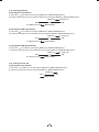
7. 3 External Sync
When using the unit with an external sync signal, input the external sync signal to EXT. SYNC terminal on the rear
panel.
When the external sync signal is input, the camera automatically switches its sync from the internal sync to the
external sync.
( 1 ) External sync signal input conditions
SYNC (75Ω unbalanced)
6D"
( 2 ) External sync frequency range
1080p/59.94Hz Setting (K(ZPPM
6(ZPPM
1080p/50Hz Setting
(K(ZPPM
6(ZPPM
1080i/59.94Hz Setting (K(ZPPM
6(ZPPM
1080i/50Hz Setting
(K(ZPPM
6(ZPPM
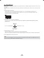
( 3 ) Using the unit with external sync signal
Adjust H (Horizontal) phase if necessary to match the output of multiple cameras.
When adjusting H (Horizontal) phase, refer to the item “7.2 (7) SYNC”.
External
Sync. signal
(3. 1) H (Horizontal) phase adjustment
Match
Observe the external sync signal and the video signal output waveform of the unit
the phase.
with a dual trace oscilloscope, and adjust H phase so that the H phases match.
Camera
Sync. output
7. 4 Synchro. Scan Operation
The shutter speed can be set by the horizontal scanning period (1H).
( 1 ) Setting by 1H
1/1125H to 1122/1125H stands for the setting by the 1H and the shutter speed can be set by the 1H.
31
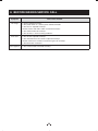
8. BEFORE MAKING SERVICE CALL
Symptom
Items to be checked
No image
s)SPOWERSUPPLIEDCORRECTLY
s)STHEPOWERSWITCHONANDTHEPOWER,%$ILLUMINATED
s)STHELENSIRISADJUSTEDCORRECTLY
s!RETHECAMERAANDVIDEOCABLESCONNECTEDCORRECTLY
s)STHESHUTTERMODESETCORRECTLY
s)STHEMONITORONANDINWORKINGCONDITION
Poor color
s)STHEMONITORADJUSTEDCORRECTLY
s)STHEWHITEBALANCEOFTHECAMERAADJUSTEDCORRECTLY
s!RETHEMATRIXCOLORCORRECTIONANDCHROMAGAINSETCORRECTLY
s)STHEILLUMINATIONSUFlCIENT
Noise appears s)STHECAMERACABLECONNECTEDSECURELY
32
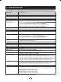
9. SPECIFICATIONS
4HESECONDITIONSAREONLYSATISlEDWHENTHECAMERACONTROLUNITISCONNECTEDTOCAMERAHEADMODEL)+($(
Power supply
$#6
Power consumption
Approx. 11.4W (including the camera head) (with the power supply voltage of 12V)
Pickup system
RGB, 3CMOS, Micro prism system
Image sensor
1/3 inch CMOS
Effective pixels
Horizontal: 1944 pixels, vertical: 1092 pixels
Output pixels
Horizontal: 1920 pixels, vertical: 1080 pixels
Scanning system
Progressive/Interlace
Scan frequency
Horizontal: 67.433kHz, vertical: 59.94Hz (at setting of 1080p/59.94Hz)
Horizontal: 56.250kHz, vertical: 50Hz (at setting of 1080p/50Hz)
Horizontal: 33.716kHz, vertical: 59.94Hz (at setting of 1080i/59.94Hz)
Horizontal: 28.125kHz, vertical: 50Hz (at setting of 1080i/50Hz)
Sync system
Internal/External (Automatic switching)
Horizontal resolution
1000TV lines standard
Vertical resolution
1000TV lines standard
Sensitivity
F10 standard (2000 lx, 3000K at 59.94Hz setting), F11 standard (2000 lx, 3000K at
50Hz setting)
Minimum illumination
4.8 lx (at 59.94Hz setting, F2.2, sensitivity +20dB, BINNING: ON)
4.0 lx (at 50Hz setting, F2.2, sensitivity +20dB, BINNING: ON)
9.6 lx (at 59.94Hz setting, F2.2, sensitivity +20dB, BINNING: OFF)
8.0 lx (at 50Hz setting, F2.2, sensitivity +20dB, BINNING: OFF)
SN ratio
D"STANDARD'!).D"$.2/&&$4,'!).'!--!/&&-!42)8/&&AND
C.TEMP 5600K during light elimination)
Ambient temperature
0°C to 40°C (32°F to 104°F)
Ambient humidity
Less than 90% (non condensing)
Weight
Approx. 610 g (1.35 lbs)
External dimension
110(W) × 40(H) ×$MMv7× 1.57”(H) ×v$ (excluding protrusions)
Scene file (user memories) !"#$%
White balance
AWB (Automatic white balance), MANUAL
Gain
AUTO (Automatic gain control), MANUAL, OFF (0dB)
Output signal
$6)DIGITAL2'"$6)$TERMINAL
1080/59.94p, 1080/50p, 1080/59.94i, 1080/50i
External sync input
39.#VALUES6D"Ω unbalanced BNC connector
(ORIZONTALK(ZPPMVERTICAL(ZPPMATP(ZSETTING
(ORIZONTALK(ZPPMVERTICAL(ZPPMATP(ZSETTING
(ORIZONTALK(ZPPMVERTICAL(ZPPMATI(ZSETTING
(ORIZONTALK(ZPPMVERTICAL(ZPPMATI(ZSETTING
Sync signal output
39.#VALUES66Ω unbalanced BNC connector
(ORIZONTALK(ZPPMVERTICAL(ZPPMAT(ZSETTING
(ORIZONTALK(ZPPMVERTICAL(ZPPMAT(ZSETTING
Interface
Serial data interface (compliant with RS-232C)
Optional parts
)+($(INCH#-/3CAMERAHEAD
IK-HR3H (1/3 inch CMOS color camera head) (Scheduled to be available in September, 2013)
%8#($!PPROXMv#AMERACABLE
%8#($!PPROXMv#AMERACABLE
%8#($!PPROXMv#AMERACABLE
%8#($!PPROXMv#AMERACABLE
Design and specifications are subject to change without notice.
33
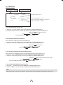
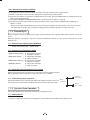
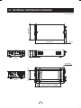
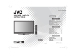
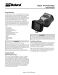
10. EXTERNAL APPEARANCE DIAGRAM
110 [4.33]
5NITMM;INCH=
11.8 [0.74]
40 [1.58]
44.6 [1.76]
186 [7.32]
[Front]
[Rear]
62 ± 0.1 [2.44 ± 0.004]
4-M 3 BD
27
[1.06]
139 ± 0.15 [5.472 ± 0.006]
34
Memo
35
Limited Warranty – TOSHIBA Camera Control Unit
The Imaging Systems Division of Toshiba America Information Systems, Inc. ("ISD") makes the following limited warranty
with regard to this CMOS Camera ("Product"). These limited warranties apply to the Original End-User "You(r)".
One (1) Year Limited Warranty of Labor and Parts
ISD warrants that this Product will perform in accordance with specifications for a period of one (1) year from the date of
purchase by the Original End-User. During this one (1) year period, ISD will repair or replace the Product, if it does not
perform as warranted. In order to take advantage of this Limited Warranty, You must: (a) deliver the Product to an ISD
Authorized Service Provider ("ASP"); and (b) pay all transportation and insurance charges for shipment of the Product to the
ASP. ISD reserves the right to substitute factory refurbished parts in place of those in need of repair.
Instruction Manual (Owner’s Manual):
You should read the Instruction Manual (Owner’s Manual) thoroughly before operating this Product. Before seeking warranty
service, you should check the troubleshooting guide in the Instruction Manual (Owner’s Manual) and follow the instructions to
correct the problem.
Your Responsibilities
This Limited Warranty is subject to the following conditions:
1. You must provide the bill of sale or proof of purchase at the time that warranty service is required.
2. All warranty servicing of the Product must be made by an ISD Authorized Service Provider.
3. You must pack the Product in its original carton using the original packing material, then insert the original carton
containing the Product into another carton with additional packing material before shipping the Product to an ASP.
4. Prepay all transportation and insurance costs.
DISCLAIMERS:
ALL OTHER EXPRESS OR IMPLIED WARRANTIES ON THIS PRODUCT, INCLUDING THE IMPLIED WARRANTIES OF
MERCHANTABILITY AND FITNESS FOR A PARTICULAR PURPOSE, ARE HEREBY DISCLAIMED. SOME STATES DO
NOT ALLOW THE EXCLUSION OF IMPLIED WARRANTIES OR LIMITATIONS ON HOW LONG AN IMPLIED WARRANTY
LASTS, SO THE ABOVE LIMITATIONS MAY NOT APPLY TO YOU.
IF THIS PRODUCT IS NOT IN GOOD WORKING ORDER AS WARRANTED ABOVE, YOUR SOLE AND EXCLUSIVE
REMEDY SHALL BE THE REPAIR OR REPLACEMENT OF THE PRODUCT. IN NO EVENT WILL ISD OR ITS PARENT
COMPANY OR ANY ASP BE LIABLE TO YOU OR ANY THIRD PARTY FOR ANY DAMAGES IN EXCESS OF THE
PURCHASE PRICE OF THE PRODUCT. THIS LIMITATION APPLIES TO DAMAGES OF ANY KIND, INCLUDING ANY
DIRECT OR INDIRECT DAMAGES, LOST PROFITS, LOST SAVINGS OR OTHER SPECIAL, INCIDENTAL, EXEMPLARY
OR CONSEQUENTIAL DAMAGES, WHETHER FOR BREACH OF CONTRACT, TORT OR OTHERWISE, OR WHETHER
ARISING OUT OF THE USE OF OR INABILITY TO USE SUCH PRODUCT, EVEN IF ISD, ITS PARENT COMPANY, OR
AN ASP HAS BEEN ADVISED OF THE POSSIBILITY OF SUCH DAMAGES OR OF ANY CLAIM BY ANY OTHER PARTY.
SOME STATES DO NOT ALLOW THE EXCLUSION OR LIMITATION OF INCIDENTAL OR CONSEQUENTIAL DAMAGES
FOR SOME PRODUCTS, SO THE ABOVE LIMITATIONS OR EXCLUSIONS MAY NOT APPLY TO YOU.
THIS LIMITED WARRANTY GIVES YOU SPECIFIC LEGAL RIGHTS, AND YOU MAY ALSO HAVE OTHER RIGHTS
WHICH MAY VARY FROM STATE TO STATE.
THIS LIMITED WARRANTY SHALL BE VOID IF THE PRODUCT OR PARTS HAVE BEEN SUBJECTED TO MISUSE,
ABUSE, ACCIDENT, IMPROPER INSTALLATION, IMPROPER MAINTENANCE, OR USE IN VIOLATION OF ISD’S
WRITTEN INSTRUCTIONS, OR WHERE THE PRODUCT HAS BEEN ALTERED OR MODIFIED WITHOUT ISD’S PRIOR
AUTHORIZATION, OR UPON THE REMOVAL OR ALTERATION OF ISD’S FACTORY SERIAL NUMBER. LABOR
SERVICE CHARGES FOR PRODUCT INSTALLATION, SET UP AND ADJUSTMENT OF CONTROLS ARE NOT
COVERED BY THIS LIMITED WARRANTY.
Questions? If you have any questions, please check ISD’s Web Site for support and a current e-mail contact to where
you can send e-mails:
Web Site: http://www.toshibacameras.com/
No person, agent, distributor, dealer, authorized service provider, or company is authorized to change, modify, or extend the
terms of this Limited Warranty in any manner whatsoever. The time within which an action must be commenced to enforce
any obligation of ISD arising under this Limited Warranty or under any statute, or law of the United States or any state thereof,
is hereby limited to one (1) year from the end of the Limited Warranty period. This limitation does not apply to implied
warranties arising under state law. Some states do not permit limitation of the time within which You may bring an action
beyond the limits provided by state law, so the above provision may not apply to You. This Limited Warranty gives You
specific legal rights and You may also have other rights which vary from state to state.
TOSHIBA AMERICA INFORMATION SYSTEMS, INC.
Imaging Systems Division
9740 Irvine Boulevard, Irvine, CA 92618-1697
Copyright© 2013 Toshiba corporation, Toshiba America Information systems, Inc. All rights reserved.