1
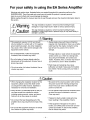
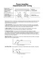
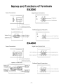
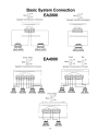
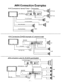
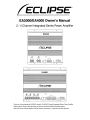
ECLIPSE®
EA2000/EA4000 Ownerls Manual
2 / 4 Channel Integrated Series Power Amplifier
0
0
EA2000
L'ECLIPSE
~.
,,,.~.
u
_
LOW'OSI
"""'" 0
"'ASI
~~,
!OO
-0
100>
6
",
00
- 00~ I'tZSlO:IO
0.
01'
SPEAKER 001
lIIl
'"
UTIO
IIIQf1
0
PIIU'"
~
0
0
19°0-01 •.
'USE
IllID6ED
_
UU
o
LJ-
TT.AEIlOIE
GICI
10001
0
o
EA4000
L'ECLIPSE
o
uuu
Thank you for purchasing the EA2000(2 channel) I EA4000(4 Channel) Intergrated Series Power Amplifier.
Please read this Owner's Manual before use. Be sure to read the Safety information section.
Keep this Owner's Manual together with the Warranty information in a safe place for later reference.
Table of contents
For your safety in using the EA Series Amplifiers
3
About Your Amplifier
4
Installation Requirements
5
Power Amplifier Adjustments and Tuning
6
Names and Functions of Terminals
9
Basic System Connection
10
AVN Connection Examples
11
Head Unit Connection Examples
12
Troubleshooting
13
Specifications
16
-2-
For your safety in using the EA Series Amplifier
Warnings and caution signs, illustrated below, are posted throughout this manual as well as on the
EA2000/EA4000. They show safe and correct ways to handle the product to prevent personal
injury to you and others and to avoid damage to property.
Before reading through the manual, take time to read through and learn the important information listed in
this section.
&Warning
& Caution
This sign indicates a situation in which incorrect handling through
disregard of a sign might result in death or serious personal injury.
This sign indicates a situation in which incorrect handling through
disregard of a sign might result in personal injury or may result solely in
damage to property.
&Warning
• This equipment requires 12V DC and should
only be installed in a vehicle with a 12V negative
ground electrical system. Any other installation
may cause a fire or other severe damage to the
equipment and the vehicle.
• Always replace fuses with fuses of identical
capacity and characteristics. Never use a higher
rated fuse than the original. Using the wrong
type of fuse may cause a fire or severe
damage.
• Do not disassemble or alter this equipment.
Accidents, fires or shocks may result.
• If foreign objects or water enters the equipment,
smoke comes out, or there is a strange odor,
stop using it immediately, and contact your
dealer. Accidents, fires, or shocks may result if
you continue to use it in these conditions.
• Do not let water or foreign objects enter the
internal parts of this equipment. Smoke, fires or
shocks may result.
• Do not use when it is broken Accidents, fires or
shocks may result.
• Plastic bags and wrappings may cause
suffocation and death. Keep away from babies
and children. Never put bag over your head or
mouth.
& Caution
• When changing the installation location for this
equipment, please consult the dealer where
you bought it for safety reasons. Expertise is
necessary for removal and installation.
• Be careful of the volume position when turning
the power source ON. Hearing damage may
result if very loud noise is emitted when the
power is turned ON.
• Keep volume to a reasonable level so that you
can hear sounds from outside the vehicle,
including warning sounds, voices, and sirens.
Failure to do so may cause an accident.
• Do not operate under abnormal conditions such
as when the sound is distorted or cuts out.
Fires may result.
• If placed in direct sunlight, metal parts may
heat, resulting in the possibility of burns.
• Do not touch the heat dissipating part of the
amplifier. Burns may result from the heat of this
part.
• If the equipment if dropped or the case is
broken, turn off the power to the main unit and
contact your dealer. If used in this condition,
fires or shocks may result.
• Do not use this equipment except for in-vehicle
use. Shocks or injuries may result.
-3-
About Your Amplifier
Your Eclipse Power Amplifier was Designed and Engineered in the USA for the best in
performance with the best components possible. In order to optimize the best
performance of your system, we recommend a professional installation by an authorized
Eclipse Dealer.
Power Supply: All Eclipse Amplifiers incorporate Powerful MOSFET Switching Power Supplies for
added reliability and powerful Music Reproduction.
Audio Amplifiers: The Eclipse Integrated Series use Symmetrical Analog Preamplifiers with Linear Bi
Polar Power Stages for Musically Accurate Audio Reproduction.
Speaker Connectors: Flush Mounted Speaker Connectors allow Clean Installation with less risk of
shorted wires. The speaker connectors will allow up to 10 Gauge wire interface.
Power Connectors: Eclipse Flush Mounted Power Connectors will accommodate up to 4 Gauge wire
for optimum power with very little Voltage Drop. As with the speaker connectors they provide less
opportunity for shorted conditions.
Fuse: Eclipse Power Amplifiers use ATC fuses. Do not replace blown fuses with fuses of a higher current
rating. This Amplifier requires maximum two 30 Amp fuses. (One 30 Amp fuse for EA2000 and two 30
Amp fuses for EA4000)
Eclipse Power On Indicator: When the Power Amplifier is powered on the Eclipse Brand Logo will
be Lighted.
Clipping Indicators: Each Amplifier has a clipping indicator LED located near the input gain control.
When the amplifier is clipping this indicator will light. This indicator will help you to adjust the input gain for
optimum performance.
-4-
Installation Requirements
Before You Start: Congratulations on your purchase of this Eclipse Power Amplifier.
The proper installation and system integration of this Power Amplifier will bring the optimum conditions for
high performance and a long trouble free life for your Mobile Audio System.
Please pay attention to the Installation hints listed in this section for the best results.
1. Amplifier Location: Avoid Areas that may have excessive Moisture, and Heat such as the Engine
Compartment, or tire wells that are prone to flooding. Never mount Power Amplifiers under Carpet
creating a "Dead Air" condition, as overheating will result. Flat surfaces will prevent potential damage to
the Heat Sinks and Bottom Cover. Always check to make sure the Power Amplifier is not mounted on
top of the Antenna Cable
2. Power Connections: B + Connections: The Power connectors will accept wire as large as 4 AWG.
For the best performance and lowest voltage drop the B+ wire should be as large as possible, and
connected directly to the positive terminal of the Car's Battery. It is recommended that a fuse, a fusible
link or a breaker be installed near the battery to protect the Car's electrical system in case a short
should occur between the battery and the Power Amplifier.
Ground Connections: The ground wire will carry the same current as the B+ wire so it should be at least
the same size. The ground wire does not have to run all of the way to the Negative Battery terminal,
because the Car Chassis in most cases is the same ground as the negative battery terminal. A good
ground screwed or bolted to the chassis where the paint has been carefully removed and conductive
grease applied will provide a lasting reliable connection. (In some cases the car's chassis may have
bad ground connections between the Battery and the Amplifier location.) If the positive wire is good
good between the Amps and the battery and a large volt drop occurs, it may be necessary to run a
good ground from the Amplifier(s) to the Negative Battery Terminal.
3. Wiring: Cleanly dressed wiring will last longer and have less chances for noise coupling and possible
damage from materials transported in compartments. Always install wires in a clean organized fashion
away from moving components, or body parts that may cut, bind, or wear through the insulation. Be
careful to route wires away from sheet metal screws that may cause intermittent shorts once the car
begins to move. Try to keep signal cables away from the power harness and the electrical harness for
the Car Electronics. Use Rubber Grommets where wiring breaks through the sheet metal as in the
engine compartment firewall or rear trunk sheet metal partition.
-5-
Power Amplifier
Adjustments and Tuning
High Pass Filter:
Stops the Low frequencies,
allows all frequencies
above the adjusted
crossover
point to be amplified.
~'"
FILTER
LJ
Low Pass Filter:
Stops the High frequencies,
allows all frequencies
below the adjusted crossover
point to be amplified.
LOW PASS
100
....
Mono
rl
llOW
INPUT
I
~"'"
I
BASS B
-~-~-
-, 0
,-, 0
odB 8
50 Hz 500 30 Hz 500
'-'
lOFF
LEVEL
HI PASS
70
'-'
~}
~
LJ
Bass Boost:
Increase the output
of low frequencies
0
8' V
,
0.2
'-'
Input Control:
Adjusts the input
sensitivity of the amplifier.
I
I
I
Adjusting and Tuning is a critical step in optimizing the performance and balance of both the Power Amps
and the Speakers in your Audio System. Careful attention to tuning will provide the best sound and a
longer life for all of the components.
1. Input Controls: Knowing the output Voltage from the Source Unit will allow you to set the Input
Controls before physically installing the Amp in the car. If the Source Unit output Voltage Specification is
4 Volts, start by setting the gain controls to about 5 Volts before installing the Amplifier.
2. Mono Switch: The Mono switch is in the OFF Position when the Amplifier is used in Stereo.
The Mono Switch will be in the ON Position when the Amplifier is in the Mono Mode.
3. Crossover Points: The Crossover Points will be adjusted before installing the Amplifier.
The Crossover Frequency is selected based on the speaker size, system configuration, and the amount of
power applied to each speaker. The smaller diameter speakers will typically be crossed over at higher
frequencies than larger diameter speakers will be. Smaller diameter speakers with less power applied can
be crossed over at a lower frequency.
High Pass Filter: The high pass filter is continuously variable between 30Hz and 500Hz, and typically
applied to front and rear Satellite Speakers.
30Hz
500Hz
......................................
~
Hi Pass Filter Selection
Low Pass Filter: The low pass filter is continuously variable between 50Hz and 500Hz, and typically
applied to Mid Bass and Subwoofers.
50Hz
~------~---~
500Hz
••••...•..............................
Lo Pass Filter Selection
-6-
4. System Power Up: Initial Tuning: Once the system is turned on and it is verified that all
channels are functional, you may load your choice of Media to set the system levels with. Media with a
good level, or lots of energy including drums, bass, voice etc is advisable. The gain controls should be
adjusted with the tone controls set to flat position and the balance and fader in the center positions on the
source unit. If a Sub Woofer level control is used with this system set it to about 1/2 or 50% of its rotation.
Turn the source unit up all of the way. If the amp channels are clipping, back down the gain controls at
each input on the amplifier. Once you can play the source unit at full power you can adjust each channel at
the amplifier until the clip light is on during the peaks. This adjustment is subjective and can be done by
observing the peak indicators on the amp as well as listening for what you determine is a safe level of
audible clipping from the speakers. The Bass Boost control can now be adjusted. The Bass Boost will
increase the electrical low frequency output of the system as much as 8 dB at 45Hz. Make sure that the
bass speaker or speakers can handle the power without damage.
Also check to make sure that the Bass or Sub woofer output of the Amplifier is not greatly overdriven.
Adjust the Front ... Rear balance so the image is optimum with the Front / Rear fader in the center
position. Understanding the type of Media that will be played back on this system is important for this
setup. If the end user will play back low dynamic range classical material, you may wish to set the gains
higher. If the end user plays back extremely high dynamic range high energy material, set the system up
so that there is a reasonable amount of protection against abuse to the components. This will guarantee a
longer life for the Speakers in the system.
This initial tuning may be done by ear and in many cases is good enough. However different types of
Media should now be played back to critique the sound performance and determine if further tuning is
nessary.
5. Bass Boost Control: The Bass boost control will boost the Low Frequency at 45Hz.
The boost control has a Range from OdB of boost to +8dB of Boost. Caution should be taken when
adjusting this control to prevent overdriving the Woofer or Overdriving the Amplifier or both.
The Clipping indicator is a good guide to use when setting the boost level.
6. Detailed Tuning: For the best overall results it is highly recommended that fine tuning of your
Audio System should be done by an Authorized Eclipse Dealer. After initial setup has been done it may be
necessary to deal with Acoustic problems that so frequently occur in Mobile Audio Systems, or particular
preferences and requirements of the end user. The detailed tuning procedures required at this point often
require the use of an Acoustic Realtime Analyzer.
If you are connecting your Power Amplifiers to an Eclipse Source Unit with the E-iSERV feature, the
real-time Analyzer will be built into the Source Unit.
(See details in your Eclipse Head unit Owner's Manual)
-7-
Quick Set Up Process
1. Set Crossover Points before installing the Amplifier based on Speaker Size and System
Configuration.
2. Turn the Gain Controls down before installing the Amplifier.
3. Turn the Bass Boost Control down, before installing the Amplifier.
4. Test the speaker wires to guarantee there are no shorts to the Car Body before connecting to
the Amplifier.
5. Connect the B+ Power, Power Ground and Remote wires to the Amplifier.
6. Connect the Speaker Wires to the Amplifier.
7. Connect the RCA Cables to the RCA inputs on the Amplifier.
8. Turn the Source Unit on and Turn the Volume down.
9. Load the Source Unit with your Set-Up Media.
10. Turn the Volume up to Maximum at the Source Unit.
11. Adjust the Gain Controls on the Amplifier one channel at a time so the Peak Indicators on the
Amplifier are just on during peaks. Listen for acceptable levels of distortion.
12. Adjust the Input Gains on the Amplifiers so the Front-Rear and Left-Right Balance sounds
correct.
13. Depending on the sound, you may wish to make small adjustments to the crossover points.
14. If Bass Boost is necessary now is the time to make adjustments.
1S.Listen to several different songs and make final adjustments by ear.
16.1f Equalization is applied a Real Time Analyzer will be useful now.
17.RTA the System and look for Peaks and Dips which should be Tuned Out.
18. Make final Adjustments with the Bass Boost Control or with the E-iSERV Process or both.
-8-
Names and Functions of Terminals
EA2000
Power Connections
Signal Input Connections
3"
+BATT. REMOTE
LINE
IN
@
FUSE
GND.
PREAHP
OUT
Hff-e-1r----- Left Signal Input
~ a
0
Hff-&fr----- Right Signal Input
RIGHT
Connect to Chassis Ground
-Remote turn on from source
Directlyt o battery with line fuse
Speaker Connections
I
I
I
SPEAKER OUT
+LEFT_
PreAmp Output Connections
+RIGHT_
lIHf
IN
I
Speaker Out L ~ ~SpeakerOut Right +
Speaker Out Left -
+
PREAMP
OUT
r - - - - - Left PreAmp Output
Speaker Out Right BRIDGED
If------ Right PreAmp Output
-
I
I
I
I
I
I
EA4000
Power Connections
FUSE
30'
30'
Signal Input Connections
+6ATT. REMOTE
00 0
rLiNE
@
GND.
FRONT
[N1
REAR
Left Front Signal Input -+----,-,=1
PREAMt OUT
-.f1"?'\\,----+--Left Rear Signal Input
0
~~---+--Right Rear
Right Front Signallnput-+----'
Signal Input
Connec t to Chassis Ground
' - - - Remote turn on from source
Directlyt o battery with line fuse
Speaker Connections
Speaker Out
Front Left +
Front LeftSpeaker Out
Front Right +_.......;==::;s
Front Right - - - - - - - - - '
PreAmp Output Connections
Speaker Out
fiiE4~;:::::==+ Rear Left +
Rear Left-
rLiNE
FRONT
LEFT
Speaker Out
'-----1--+ Rear Right +
""----+ Rear Right -
RIGHT
-9-
1N1
REAR
PREA1P OUT
1 - - - - - ' - - - Left PreAmp Output
!----i---Right PreAmp Output
Basic System Connection
EA2000
~o
l JON
Mono
LJ
Mono
lOFF
Speaker Connections 2 Channel
~
JON
R
LJ
1 OFF
Speaker Connections Bridged
SPEAKER OUT
+LEFT_
+
, r==="J ,
+"IGHT_
BRIDGED
, r==="J
+
+
Front / Rear
Mono
l JON
~o
EA4000
LJ
Front
Mono
lOFF
Speaker Connections 4 Channel
.
-I
l
~o
JON
LJ
1 OFF
Rear
Mono
~JON
~
LJ
1 OFF
Speaker Connections 3 Channel
SPEAKER OUT
FRONT
+lEFT_
+RIGHT_
Front / Rear
Mono
~
il
LJ
JON
lOFF
Speaker Connections Bridged
SPEAKER OUT
FRONT
+LEFI_
+RIGHT_
- 10 -
AVN Connection Examples
AVN Connections Internal Power + Subwoofers
.
EA2000
II. _.III
E8. :
Non-Fader Out
':
Left Channel
~
~
1::::::=======I==F======:l
Right Channel
, ,
Front Left Speaker
Front Right Speaker
Front
Rear Left Speaker
Rear
Rear Right Speaker
AVN Connections EA4000 example of 3 channel install
EA4000
..
••
Sub
Front Out
Non-Fader Out
Front
AVN connection using the EA2000 and EA4000
EA2000 Bridged
Non Fader Out
..
Front
EA4000
•
•
Front Out
Rear Out
l...----r---~'11
- 11 -
Rear
Head Unit Connection Examples
Head Unit Connections Internal Power + Subwoofers
Left Channel
Non-Fader Out
~~~
._t:;'l
--'~
_ _ _ _ _F_ro_nt_Le_ft_Sp_ea_ke_r
Front
Front Right Speaker
Rear Left Speaker
Rear
Rear Right Speaker
AVN Connections EA4000 example of 3 channel install
EA4000
••
Front Out
Sub
rD
'-------1Lo
Non-Fader Out
Front
Head Unit connection using the EA2000 and EA4000
EA2000 Bridged
OOlooot
Non Fader Out
Front
EMOOO
••
=
~-
-
OOlo;or
Rear
Front Out
Rear Out
Troubleshooting
If a problem occurs after your system is installed, please refer to this troubleshooting section
for solutions. If after carefully following these instructions you still have a problem, please
contact Eclipse Technical Supporl at 1-800-233-2216
Problem
Possible Cause
1. Amp won't power on
No fuse installed in the amplifier or fuse
is blown
Install fuse.
Battery B+ not Powered on
Check for 12V at Amp B+ Terminal:
Make sure B+ Cable is connected to the
Battery.
Ground Cable is not connected
Check for 12V between B+ amp
connector and Amp Ground Connector:
Make sure ground Cable is connected to
both amp and vehicle Ground.
Remote line in is not powering on
Aftertuming the Sourre on. measure for voltage
Between amp pwr gnd and remote terminal
Make sure the remote wire is connected to
the correct remote output from the source
unit.check connections and power at
source unit.
Power Cables in Reverse Polarity
Make sure B+ and Pwr GND cables are
connected to the correct terminals:
Connect correctly.
Wrong size fuse installed in amplifier
Make sure fuse size is correct:
Check spec Sheet ( back of this book) for
correct size.
RCA cables not connected
Make sure RCA cables are connected on
both ends:
Make connections.
Test RCA Cable for Signal: Replace if
necessary.
2. Amp Blows Fuses
3. Amp is on but no
sound from one or
more channels
Defective RCA Cable
Speaker wires not connected
4. Amplifier goes into
protect mode
Possible Solution
Make sure speaker wires are connected
on both ends:
Make connections.
Speaker wires connected to wrong
terminals
Make sure speaker wires are connected
to the correct terminals.
Input Gain Controls turned down
Make sure gains are adjusted to source unit.
one or more speakers is shorted
Make sure there are no speaker shorts
with the amplifier turned off:
Disconnect speaker from amp and test for
a short across the Speaker.
Test for a short between the speaker and
chassis or body of the car.
With the speakers connected and amp
turned off:
Test for a short between the amplifier
output and the chassis or body of the car.
- 13 -
Problem
Possible Cause
5. Amp has engine noise Speaker ground is shorted to car body
6. Distorted Output
Test for negative speaker speaker short:
Make sure negative speaker lead is not
shorted to vehicle chassis or body.
Outer barrel of RCA connector is
shorting to the Amplifier chassis
With amp off. disconnect RCA Cables And
test for the impedance between the Barrel
of the RCA and the amp power ground.
If no negative speaker lead short, the
impedance is nearly shorted (low resistance).
Call Eclipse Technical support.
Amplifier gain is too high
Turn amplifier gain down so clipping
LED turns on during peaks, or level is just
below audible distortion.
Too much input signal
Source unit output level is more then 8
Volts RMS: Reduce gain at Source Unit.
Damaged Speaker
Check Speaker with alternative Source:
Replace Speaker.
Source Unit output is distorted
Test Source Unit with alternate system
like a Display or function verification unit.
Replace Source Unit.
7. Unit Turns on and off Speaker is shorted
8. Poor Bass Output
Possible Solution
Test for shorted speaker: Remove short
from speaker, or replace shorted Speaker.
Poor connection to Power wires or Poor
Battery connection
Test connections at B+ cable and Power
Ground: Repair Power Cable connections.
Gain Control for Subwoofer is too low
Check Source Unit settings and Input
Gain Control: Adjust gain control on
Source Unit or at amplifier input.
Crossover is set up incorrectly
Check crossover frequency settings:
Adjust Crossover.
Subwoofer is wired out of phase
Check subwoofer wiring and phase:
Correct wiring of subwoofer to be in phase.
Acoustical misalignment of subwoofer
Check to be sure the box is not to small
for the Subwoofer operating parameters
Correct box size.
Tone Controls on Source Set Incorrectly Check to make sure the tone controls are
set to a flat position and not to cut position:
Set tone controls to flat or by pass position.
- 14-
Problem
Possible Cause
9. Speaker pops when Source unit may be sending pop noise to
unit is turned on or off amplifier
Possible Solution
Disconnect RCA inputs then turn source
unit on and off:
If pop noise is gone try a different Source Unit.
Possible ground loop noise
Check to make sure grounds are correct
so No ground loops can exist:
If a poor ground exists correct the grounding.
DC offset at amplifier output
Measure the amount of DC voltage
across the speaker connectors at the
output of the Amplifier:
If the DC offset voltage at the amplifier
output is greater then 70mV it will cause a
turn on sound. Change the amplifier.
10. Bass Boost Distorted Input gain set too high or remote sub level
control is turned all the way up
Check gain settings:
Readjust gain settings with remote sub
control at center position.
11. Amp runs hot
Make sure unit has proper ventilation:
Check load impedance against the
specifications:
Inadequate ventilation
Load impedance is too low
Connect the proper load impedance.
12. Amp won't shut off Remote on wire is staying high or at 12V
Measure voltage between Remote on
terminal and the power ground terminal:
If the voltage is high disconnect the
Source Unit and see if the amp shuts off.
If it does try a different source unit.
- 15 -
Specifications
Power Output: RMS Power at 14.4 Volt Power Supplv@ < .1% THO
-------------EA2000------------60WX2
4 n @ 20 Hz to 20 KHz Stereo
175W X 1
4 n @ 20 Hz to 20 KHz Bridged
@ 20 Hz to 20 KHz Stereo ( CEA 2006 ) <1 % THO
4n
-------------EA4000------------75WX4
4 n @ 20 Hz to 20 KHz Stereo
150W X2
4 n @ 20 Hz to 20 KHz Bridged
4 n @ 20 Hz to 20 KHz Stereo ( CEA 2006 ) <1 % THO
Max Power Output: Peak Music Power at 14.4 Volt Power Supplv
-------------EA2000------------90WX2
4 n Stereo @ 1 KHz
4n
Bridged @ 1 KHz
225W X 1
-------------EA4000------------100WX4
4 n Stereo @ 1 KHz
175WX2
4n
Bridged @ 1 KHz
Input Sensitivity
200mV ... 8V
High Pass Frequency Selection Variable
30 Hz ... 500 Hz
low Pass Frequency Selection Variable
50 Hz ... 500 Hz
Bass Boost
0- 8dB @45 Hz
Subsonic Filter
18dB / octave @ 20 Hz
Signal to Noise ( CEA 2006 )
> 100 dB
Frequency Response
+0, -.5 dB
20Hz - 20KHz
Channel Separation
< 70 dB
Damping Factor
EIA / IHF
Quiescent Current ( Idle Current)
> 50 dB
:: 1 Amp
Maximum Current
EA2000 30Amps
EA4000 60Amps
Amp Protect Temperature (Heat Sink)
- 16 -
90C
- 17 -
- 18 -
- 19 -
CUSTOMER NOTICE
Please retain this booklet and write in the serial number
of your new Amplifier for identification.
The serial number is labeled or stamped on the chassis.
Serial No.
FUJITSU TEN LIMITED
Contact: FUJITSU TEN CORP.OF AMERICA
19600 So. Vermont Avenue, Torrance, CA 90502
800·233·2216
www.eclipse-web.com
"ECLIPSE" is a registered trademark of
FUJITSU TEN LIMITED in 48 countries
including the U.S. and Japan.
090003-285007000503(CN,K)
LECLIPSE
IMPORTANT
SHOULD YOU HAVE ANY QUESTIONS,
call: 1-800-233-2216
OJ
FUJITSU TEN
FUJITSU TEN CORP. OF AMERICA
19600 S. Vermont Avenue, Torrance, CA 90502
PLACE
FIRST-CLASS
STAMP
HERE
FUJITSU TEN CORP. OF AMERICA
Warranty Registration
19600 S. Vermont Avenue
Torrance, CA 90502
ECLIPSE LIMITED WARRANTY
Eclipse (a division of Fujitsu Ten Corp. of America) hereby warrants your Eclipse product to be free from defects in material and
workmanship for a period of one year from the original date of purchase. This warranty applies only to the original consumerpurchaser (this warranty is not transferable), and only when this product is originally purchased from an authorized Eclipse retailer
in the United States or Canada.
For a period of one year from the date of original purchase, in the unlikely event that your Eclipse unit should fail, Eclipse shall,
under this warranty, repair or replace with a like mOdel any unit which is defective in material or workmanship, if returned to an
authorized Eclipse retailer, transportation prepaid Eclipse shall either repair or replace, at its sole discretion, the Eclipse product
at no charge to the original purchaser during the warranty period. Service work must be performed by an authorized Eclipse service department or retailer in order for the owner to receive the benefits of this warranty
Eclipse shall not refund, nor be responsible for, any expenses paid or incurred by the owner under this warranty.
THERE ARE NO WARRANTIES, WHICH EXTEND BEYOND THE DESCRIPTION ON THE FACE HEREOF
EXCLUSIONS FROM ECLIPSE'S LIMITED WARRANTY
This warranty shall not cover
1. Elimination of car static. motor nOise. or other electrrcallnterference, correctIOn of problems resulting from the antenna system. CO's, MO's.
tape cartrrdges and or audiO cables. etc
2. Any defects In the opinion of Eclipse. caused by abuse. misuse, accident (including any damages caused by acts of God such as flood, lightning or fluctuation in electrical power), liquid damage or damage caused by attempted theft or negligent use. Failure to perform reasonable
and necessary maintenance, improper Installation (such as insufficient grounding), Improper Installation of other components, mOdification
or serVice by non-authorized Eclipse Service Department, use of component parts not approved by Eclipse Damage caused In transit or in
handling, or when the model's serral number has been removed, altered Or defaced
3. Cosmetic damage accessorres (SUCh as magazines or remotes) or problems or damage caused by the application or use of defective media
4. Normal wear. tear. battery replacement and any perrodlc maintenance
5. Does not cover removal and reinstallation of product
rHIS WARRANTY IS IN LIEU OF ALL OTHE,q EXPRESS OR IMPLifO WARRANTiES. STATEMENrs OR REp·
RfSfNrAflONS. AND UNLESS SrATfD HEREIN. ALl SUCH WARRANfJfS STATEMENTS OR REPRESENWIONS
MADE BY ANY PERSON OR FIRM ARE VOiD ALL IMPLifO WARRANflES IN CONNECTION WITH THIS SAL [
INCLUDJNG THE WARRANTY O~ MERCHANTA811,/1Y AND THF WARRANTY OF FITNESS FOR A PARTICULAR USt
ARE HEREBY MODIFIED TO EXIST ONLY AS CONTAINED IN /HIS LiMITED WARRANTy AND SHALL BE OF THi
SAME DURATION AS THE WARRANTY PERIOD STATED ABOVE SOME STATES DO NOT ALLOW LlMITMIONS ON
HOW LONG AN IMPLIED WARRANTY LASTS.
THE ABovt i/MJrATlO,V MAY NO! APPLY TO YOU
iN THE [VENT THAT YOUR ECuPSE PRODUCT SHAL! PROVE DEFECTIVE iN WORKMANSHIP OR MATfRI
ALS '!'OUR SOLE REMEDY SHALL 6E iHE REPAIR OR REPLACEMENT REMEDY AS STATED IN THIS WARRANT~
AND UNDER NO CIRCuMSTANCES SHALt ECLIPSE B£ LIABlE ;OR ANY LOSS OR DAMAGE. WHETHER DIRECT.
INCIDENTAL OR CON5EOUENTJAL. MUSING OUi OF THE USE OF. OR iNABIl In' TO USE. THIS ECLiPSE PRODUCT
SOME STATES 00 NOT ALLOW THE EXCLUSION OR LIMITATION Of INCIDENTAL OR CONSEQUENTIAL DAMAGES
SO THE ABOVE LIMITATION OR EXCLUSION MAY NOT APPI Y TO YOU
TO OBTAIN WARRANTY SERVICE
MUST GO BACK TO AN AUTHORllEO iCt/PSt RETAiLER WITHIN THE
WARRANTY PERIOD. YOUR PROOf Of PURCHASE. SUCH AS A BILL Of SAlE OR RECEIPTEO INVOICE THATINOI·
CATES ThAT THE UNiT !S WiTH"'; THE WARRANTY PERIOD. MUST Sf PRESENTED TO OBTAiN WARRANTY S£R
VICE vOU WILL BE RESPONSIBLE fOR SHIPPING CHARGES ro ECLIPSE ECUPSE WILL RfPAIR THE DEFEe
'IVl UNIT OR R£PtAC[ f~ AlliS SOLE DISCR£1fON WITH A i./KE MODEL WITrlOUT CHARGE IF ALL WARRA~·
lY CON[.IIT/ONS ARE MET fC:..,PSf WILL COVER SHiPPING OiARGtS TO qflURN THE UNIT TO YOU
so
EA2000
I""'" "'" """'" "'" "'" """"
you
Please detach here before mailing.
LECLIPSE
090000-01270700
0503MT(N)
Model Number:
1111I1111111111111111111I1111I1111I1111I
EA2000
Please print or type the information
listed below and mail.
Serial Number:
I
I I
Reta iIe r's Name: L--'---'-I_-'---'-......J._-"---"----J_..L..-L_L--'---'-_'---'---'-_-"---'----'_.L--'----''---'--'
Street:
I I
I I
I
I I
I I- I I I-I I
Month
Day
Yea:
I I I
I I
City
1
Date of Pu rchase
Car Make:
: . Mr.
Mrs.
Ms.
first Name
Owne r's Name:
Street:
1 I
City
1
Phone Numbe r:
LI---,1_-'--'---..JL-..L..-1.._'---'---'-_-'---'---'
1
1 I
-1'----'--'------'_-'---'----'---'
--,-1_.1--'-_'---'--'----'----''---"---'----'----''---'---'--'--'
...
Insta II er:
LI
Owner's E-mail Address
Comments:
We will be sending you a questionnaire to assist us in developing new products for you
Which method is most convenient?
E-mail
. Mail
_
Thank You.