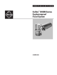
1
OPERATION/PROGRAMMING
ExSite™ Series
Explosionproof
Positioning System
C1300M-B (6/05)
Contents
Regulatory Notices . . . . . . . . . . . . . . . . . . . . . . . . . . . . . . . . . . . . . . . . . . . . . . . . . . . . . . . . . . . . . . . . . . . . . . . . . . . . . . . . . . . . . . . . . . 5
Welcome . . . . . . . . . . . . . . . . . . . . . . . . . . . . . . . . . . . . . . . . . . . . . . . . . . . . . . . . . . . . . . . . . . . . . . . . . . . . . . . . . . . . . . . . . . . . . . . . . .
Models . . . . . . . . . . . . . . . . . . . . . . . . . . . . . . . . . . . . . . . . . . . . . . . . . . . . . . . . . . . . . . . . . . . . . . . . . . . . . . . . . . . . . . . . . . .
Getting Started . . . . . . . . . . . . . . . . . . . . . . . . . . . . . . . . . . . . . . . . . . . . . . . . . . . . . . . . . . . . . . . . . . . . . . . . . . . . . . . . . . . . .
Set the Calibration Point. . . . . . . . . . . . . . . . . . . . . . . . . . . . . . . . . . . . . . . . . . . . . . . . . . . . . . . . . . . . . . . . . . . . . . . . . . . . . .
6
6
6
6
How to Operate Your System . . . . . . . . . . . . . . . . . . . . . . . . . . . . . . . . . . . . . . . . . . . . . . . . . . . . . . . . . . . . . . . . . . . . . . . . . . . . . . . . . .
Accessing Main Menu (Preset 95). . . . . . . . . . . . . . . . . . . . . . . . . . . . . . . . . . . . . . . . . . . . . . . . . . . . . . . . . . . . . . . . . . . . . . . . . . .
CM6700/CM6800 . . . . . . . . . . . . . . . . . . . . . . . . . . . . . . . . . . . . . . . . . . . . . . . . . . . . . . . . . . . . . . . . . . . . . . . . . . . . . . . . . . .
KBD200A/KBD300A (Direct Mode Only) . . . . . . . . . . . . . . . . . . . . . . . . . . . . . . . . . . . . . . . . . . . . . . . . . . . . . . . . . . . . . . . . .
CM9500. . . . . . . . . . . . . . . . . . . . . . . . . . . . . . . . . . . . . . . . . . . . . . . . . . . . . . . . . . . . . . . . . . . . . . . . . . . . . . . . . . . . . . . . . . .
CM9740/CM9760/CM9770/CM9780. . . . . . . . . . . . . . . . . . . . . . . . . . . . . . . . . . . . . . . . . . . . . . . . . . . . . . . . . . . . . . . . . . . .
KBD4000/KBD4002 (Genex multiplexer) . . . . . . . . . . . . . . . . . . . . . . . . . . . . . . . . . . . . . . . . . . . . . . . . . . . . . . . . . . . . . . . . .
MPT9500. . . . . . . . . . . . . . . . . . . . . . . . . . . . . . . . . . . . . . . . . . . . . . . . . . . . . . . . . . . . . . . . . . . . . . . . . . . . . . . . . . . . . . . . . .
PelcoNet . . . . . . . . . . . . . . . . . . . . . . . . . . . . . . . . . . . . . . . . . . . . . . . . . . . . . . . . . . . . . . . . . . . . . . . . . . . . . . . . . . . . . . . . . .
7
8
8
8
8
8
8
8
8
Quick Start Guide – System Setup . . . . . . . . . . . . . . . . . . . . . . . . . . . . . . . . . . . . . . . . . . . . . . . . . . . . . . . . . . . . . . . . . . . . . . . . . . . . . . 9
Language . . . . . . . . . . . . . . . . . . . . . . . . . . . . . . . . . . . . . . . . . . . . . . . . . . . . . . . . . . . . . . . . . . . . . . . . . . . . . . . . . . . . . . . . . . . . . . . . . 11
Unit Inversion . . . . . . . . . . . . . . . . . . . . . . . . . . . . . . . . . . . . . . . . . . . . . . . . . . . . . . . . . . . . . . . . . . . . . . . . . . . . . . . . . . . . . . . . . . . . . . 12
System Information . . . . . . . . . . . . . . . . . . . . . . . . . . . . . . . . . . . . . . . . . . . . . . . . . . . . . . . . . . . . . . . . . . . . . . . . . . . . . . . . . . . . . . . . . 13
Display Setup . . . . . . . . . . . . . . . . . . . . . . . . . . . . . . . . . . . . . . . . . . . . . . . . . . . . . . . . . . . . . . . . . . . . . . . . . . . . . . . . . . . . . . . . . . . . . . 14
Label Position. . . . . . . . . . . . . . . . . . . . . . . . . . . . . . . . . . . . . . . . . . . . . . . . . . . . . . . . . . . . . . . . . . . . . . . . . . . . . . . . . . . . . . . . . . 15
Unit Settings . . . . . . . . . . . . . . . . . . . . . . . . . . . . . . . . . . . . . . . . . . . . . . . . . . . . . . . . . . . . . . . . . . . . . . . . . . . . . . . . . . . . . . . . . . . . . .
Camera. . . . . . . . . . . . . . . . . . . . . . . . . . . . . . . . . . . . . . . . . . . . . . . . . . . . . . . . . . . . . . . . . . . . . . . . . . . . . . . . . . . . . . . . . . . . . . .
Type of Lighting. . . . . . . . . . . . . . . . . . . . . . . . . . . . . . . . . . . . . . . . . . . . . . . . . . . . . . . . . . . . . . . . . . . . . . . . . . . . . . . . . . . .
Auto Focus . . . . . . . . . . . . . . . . . . . . . . . . . . . . . . . . . . . . . . . . . . . . . . . . . . . . . . . . . . . . . . . . . . . . . . . . . . . . . . . . . . . . . . .
Zoom Limit . . . . . . . . . . . . . . . . . . . . . . . . . . . . . . . . . . . . . . . . . . . . . . . . . . . . . . . . . . . . . . . . . . . . . . . . . . . . . . . . . . . . . . .
Zoom Speed . . . . . . . . . . . . . . . . . . . . . . . . . . . . . . . . . . . . . . . . . . . . . . . . . . . . . . . . . . . . . . . . . . . . . . . . . . . . . . . . . . . . . .
Low Light Limit . . . . . . . . . . . . . . . . . . . . . . . . . . . . . . . . . . . . . . . . . . . . . . . . . . . . . . . . . . . . . . . . . . . . . . . . . . . . . . . . . . . .
IR Cut Filter (23X Day/Night Camera). . . . . . . . . . . . . . . . . . . . . . . . . . . . . . . . . . . . . . . . . . . . . . . . . . . . . . . . . . . . . . . . . . .
Advanced Camera Settings . . . . . . . . . . . . . . . . . . . . . . . . . . . . . . . . . . . . . . . . . . . . . . . . . . . . . . . . . . . . . . . . . . . . . . . . . . . . . . .
Shutter Speed . . . . . . . . . . . . . . . . . . . . . . . . . . . . . . . . . . . . . . . . . . . . . . . . . . . . . . . . . . . . . . . . . . . . . . . . . . . . . . . . . . . . .
AGC Limit . . . . . . . . . . . . . . . . . . . . . . . . . . . . . . . . . . . . . . . . . . . . . . . . . . . . . . . . . . . . . . . . . . . . . . . . . . . . . . . . . . . . . . . .
Auto Iris. . . . . . . . . . . . . . . . . . . . . . . . . . . . . . . . . . . . . . . . . . . . . . . . . . . . . . . . . . . . . . . . . . . . . . . . . . . . . . . . . . . . . . . . . .
Auto Sharpness. . . . . . . . . . . . . . . . . . . . . . . . . . . . . . . . . . . . . . . . . . . . . . . . . . . . . . . . . . . . . . . . . . . . . . . . . . . . . . . . . . . .
Auto White Balance . . . . . . . . . . . . . . . . . . . . . . . . . . . . . . . . . . . . . . . . . . . . . . . . . . . . . . . . . . . . . . . . . . . . . . . . . . . . . . . .
Backlight Compensation (BLC) . . . . . . . . . . . . . . . . . . . . . . . . . . . . . . . . . . . . . . . . . . . . . . . . . . . . . . . . . . . . . . . . . . . . . . . .
Video Level . . . . . . . . . . . . . . . . . . . . . . . . . . . . . . . . . . . . . . . . . . . . . . . . . . . . . . . . . . . . . . . . . . . . . . . . . . . . . . . . . . . . . . .
Wide Dynamic Range (23X Day/Night Camera). . . . . . . . . . . . . . . . . . . . . . . . . . . . . . . . . . . . . . . . . . . . . . . . . . . . . . . . . . .
Motion . . . . . . . . . . . . . . . . . . . . . . . . . . . . . . . . . . . . . . . . . . . . . . . . . . . . . . . . . . . . . . . . . . . . . . . . . . . . . . . . . . . . . . . . . . . . . . .
Proportional Pan . . . . . . . . . . . . . . . . . . . . . . . . . . . . . . . . . . . . . . . . . . . . . . . . . . . . . . . . . . . . . . . . . . . . . . . . . . . . . . . . . . .
Park Time. . . . . . . . . . . . . . . . . . . . . . . . . . . . . . . . . . . . . . . . . . . . . . . . . . . . . . . . . . . . . . . . . . . . . . . . . . . . . . . . . . . . . . . . .
Scan Speed . . . . . . . . . . . . . . . . . . . . . . . . . . . . . . . . . . . . . . . . . . . . . . . . . . . . . . . . . . . . . . . . . . . . . . . . . . . . . . . . . . . . . . .
preset freeze frame. . . . . . . . . . . . . . . . . . . . . . . . . . . . . . . . . . . . . . . . . . . . . . . . . . . . . . . . . . . . . . . . . . . . . . . . . . . . . . . . .
Limit Stops . . . . . . . . . . . . . . . . . . . . . . . . . . . . . . . . . . . . . . . . . . . . . . . . . . . . . . . . . . . . . . . . . . . . . . . . . . . . . . . . . . . . . . .
Azimuth Zero. . . . . . . . . . . . . . . . . . . . . . . . . . . . . . . . . . . . . . . . . . . . . . . . . . . . . . . . . . . . . . . . . . . . . . . . . . . . . . . . . . . . . .
Power Up . . . . . . . . . . . . . . . . . . . . . . . . . . . . . . . . . . . . . . . . . . . . . . . . . . . . . . . . . . . . . . . . . . . . . . . . . . . . . . . . . . . . . . . . . . . . .
Power Up Action . . . . . . . . . . . . . . . . . . . . . . . . . . . . . . . . . . . . . . . . . . . . . . . . . . . . . . . . . . . . . . . . . . . . . . . . . . . . . . . . . . .
Line Sync . . . . . . . . . . . . . . . . . . . . . . . . . . . . . . . . . . . . . . . . . . . . . . . . . . . . . . . . . . . . . . . . . . . . . . . . . . . . . . . . . . . . . . . . . . . . .
C1300M-B (6/05)
16
16
16
16
16
16
16
17
18
18
18
19
19
19
20
20
20
21
21
22
23
23
24
25
26
26
27
3
Presets . . . . . . . . . . . . . . . . . . . . . . . . . . . . . . . . . . . . . . . . . . . . . . . . . . . . . . . . . . . . . . . . . . . . . . . . . . . . . . . . . . . . . . . . . . . . . . .
Enable Motion Detection (23X Day/Night Camera) . . . . . . . . . . . . . . . . . . . . . . . . . . . . . . . . . . . . . . . . . . . . . . . . . . . . . . . .
Edit Detection Areas (23X Day/Night Camera) . . . . . . . . . . . . . . . . . . . . . . . . . . . . . . . . . . . . . . . . . . . . . . . . . . . . . . . . . . .
Activate AUX Command (23X Day/Night Camera). . . . . . . . . . . . . . . . . . . . . . . . . . . . . . . . . . . . . . . . . . . . . . . . . . . . . . . . .
AUX Time (23X Day/Night Camera) . . . . . . . . . . . . . . . . . . . . . . . . . . . . . . . . . . . . . . . . . . . . . . . . . . . . . . . . . . . . . . . . . . . .
Patterns . . . . . . . . . . . . . . . . . . . . . . . . . . . . . . . . . . . . . . . . . . . . . . . . . . . . . . . . . . . . . . . . . . . . . . . . . . . . . . . . . . . . . . . . . . . . . .
Zones . . . . . . . . . . . . . . . . . . . . . . . . . . . . . . . . . . . . . . . . . . . . . . . . . . . . . . . . . . . . . . . . . . . . . . . . . . . . . . . . . . . . . . . . . . . . . . . .
Window Blanking. . . . . . . . . . . . . . . . . . . . . . . . . . . . . . . . . . . . . . . . . . . . . . . . . . . . . . . . . . . . . . . . . . . . . . . . . . . . . . . . . . . . . . .
Reverse . . . . . . . . . . . . . . . . . . . . . . . . . . . . . . . . . . . . . . . . . . . . . . . . . . . . . . . . . . . . . . . . . . . . . . . . . . . . . . . . . . . . . . . . . .
Clear Window . . . . . . . . . . . . . . . . . . . . . . . . . . . . . . . . . . . . . . . . . . . . . . . . . . . . . . . . . . . . . . . . . . . . . . . . . . . . . . . . . . . . .
Blank All Above/Blank All Below . . . . . . . . . . . . . . . . . . . . . . . . . . . . . . . . . . . . . . . . . . . . . . . . . . . . . . . . . . . . . . . . . . . . . .
Alarms . . . . . . . . . . . . . . . . . . . . . . . . . . . . . . . . . . . . . . . . . . . . . . . . . . . . . . . . . . . . . . . . . . . . . . . . . . . . . . . . . . . . . . . . . . . . . . .
Wiper . . . . . . . . . . . . . . . . . . . . . . . . . . . . . . . . . . . . . . . . . . . . . . . . . . . . . . . . . . . . . . . . . . . . . . . . . . . . . . . . . . . . . . . . . . . . . . . .
Wiper Control . . . . . . . . . . . . . . . . . . . . . . . . . . . . . . . . . . . . . . . . . . . . . . . . . . . . . . . . . . . . . . . . . . . . . . . . . . . . . . . . . . . . .
Wiper Mode . . . . . . . . . . . . . . . . . . . . . . . . . . . . . . . . . . . . . . . . . . . . . . . . . . . . . . . . . . . . . . . . . . . . . . . . . . . . . . . . . . . . . .
Wiper Dwell . . . . . . . . . . . . . . . . . . . . . . . . . . . . . . . . . . . . . . . . . . . . . . . . . . . . . . . . . . . . . . . . . . . . . . . . . . . . . . . . . . . . . .
Wiper Time . . . . . . . . . . . . . . . . . . . . . . . . . . . . . . . . . . . . . . . . . . . . . . . . . . . . . . . . . . . . . . . . . . . . . . . . . . . . . . . . . . . . . . .
Set Washer Sequence . . . . . . . . . . . . . . . . . . . . . . . . . . . . . . . . . . . . . . . . . . . . . . . . . . . . . . . . . . . . . . . . . . . . . . . . . . . . . . . . . . .
AUX . . . . . . . . . . . . . . . . . . . . . . . . . . . . . . . . . . . . . . . . . . . . . . . . . . . . . . . . . . . . . . . . . . . . . . . . . . . . . . . . . . . . . . . . . . . . . . . . .
Clear. . . . . . . . . . . . . . . . . . . . . . . . . . . . . . . . . . . . . . . . . . . . . . . . . . . . . . . . . . . . . . . . . . . . . . . . . . . . . . . . . . . . . . . . . . . . . . . . .
Password . . . . . . . . . . . . . . . . . . . . . . . . . . . . . . . . . . . . . . . . . . . . . . . . . . . . . . . . . . . . . . . . . . . . . . . . . . . . . . . . . . . . . . . . . . . . .
28
29
29
30
30
31
32
33
34
34
34
35
38
38
38
38
38
39
40
41
42
Position Calibration . . . . . . . . . . . . . . . . . . . . . . . . . . . . . . . . . . . . . . . . . . . . . . . . . . . . . . . . . . . . . . . . . . . . . . . . . . . . . . . . . . . . . . . . . 43
Reset, Cycle Power, Reboot . . . . . . . . . . . . . . . . . . . . . . . . . . . . . . . . . . . . . . . . . . . . . . . . . . . . . . . . . . . . . . . . . . . . . . . . . . . . . . . . . . .
Reset Camera . . . . . . . . . . . . . . . . . . . . . . . . . . . . . . . . . . . . . . . . . . . . . . . . . . . . . . . . . . . . . . . . . . . . . . . . . . . . . . . . . . . . .
Cycle Camera Power. . . . . . . . . . . . . . . . . . . . . . . . . . . . . . . . . . . . . . . . . . . . . . . . . . . . . . . . . . . . . . . . . . . . . . . . . . . . . . . .
Reboot System . . . . . . . . . . . . . . . . . . . . . . . . . . . . . . . . . . . . . . . . . . . . . . . . . . . . . . . . . . . . . . . . . . . . . . . . . . . . . . . . . . . .
44
44
44
44
Software/Language File Upload . . . . . . . . . . . . . . . . . . . . . . . . . . . . . . . . . . . . . . . . . . . . . . . . . . . . . . . . . . . . . . . . . . . . . . . . . . . . . . . 45
Upload Icon . . . . . . . . . . . . . . . . . . . . . . . . . . . . . . . . . . . . . . . . . . . . . . . . . . . . . . . . . . . . . . . . . . . . . . . . . . . . . . . . . . . . . . . . . . . 45
Specifications . . . . . . . . . . . . . . . . . . . . . . . . . . . . . . . . . . . . . . . . . . . . . . . . . . . . . . . . . . . . . . . . . . . . . . . . . . . . . . . . . . . . . . . . . . . . . . 46
4
C1300M-B (6/05)
Regulatory Notices
This device complies with Part 15 of the FCC Rules. Operation is subject to the following two conditions: (1) this device may not cause
harmful interference, and (2) this device must accept any interference received, including interference that may cause undesired
operation.
RADIO AND TELEVISION INTERFERENCE
This equipment has been tested and found to comply with the limits of a Class B digital device, pursuant to Part 15 of the FCC Rules.
These limits are designed to provide reasonable protection against harmful interference in a residential installation. This equipment
generates, uses, and can radiate radio frequency energy and, if not installed and used in accordance with the instructions, may cause
harmful interference to radio communications. However there is no guarantee that the interference will not occur in a particular
installation. If this equipment does cause harmful interference to radio or television reception, which can be determined by turning
the equipment off and on, the user is encouraged to try to correct the interference by one or more of the following measures:
• Reorient or relocate the receiving antenna.
• Increase the separation between the equipment and the receiver.
• Connect the equipment into an outlet on a circuit different from that to which the receiver is connected.
• Consult the dealer or an experienced radio/TV technician for help.
You may also find helpful the following booklet, prepared by the FCC: “How to Identify and Resolve Radio-TV Interference Problems.”
This booklet is available from the U.S. Government Printing Office, Washington D.C. 20402.
Changes and Modifications not expressly approved by the manufacturer or registrant of this equipment can void your authority to
operate this equipment under Federal Communications CommissionÕs rules.
This Class B digital apparatus complies with Canadian ICES-003.
Cet appareil numérique de la classe B est conforme à la norme NMB-003 du Canada.
C1300M-B (6/05)
5
Welcome
Thank you for purchasing Pelco’s ExSite™ IPSXM Series explosionproof positioning system. Your new system features a high resolution,
camera/optics package with programmable software.
This manual is designed to be a reference tool for the operation and programming of your system. Inside you will find information about the
features and commands of your IPSXM system, as well as a detailed menu tree.
MODELS
IPSXM30C22-2
IPSXM30C22-2X
IPSXM31C22-2
IPSXM31C22-2X
IPSXM30CBW23-2
IPSXM30CBW23-2X
IPSXM31CBW23-2
IPSXM31CBW23-2X
IPSXM30C22-7
IPSXM30C22-7X
IPSXM31C22-7
IPSXM31C22-7X
IPSXM30CBW23-7
IPSXM30CBW23-7X
IPSXM31CBW23-7
IPSXM31CBW23-7X
Pan and tilt system with color camera, 60 Hz, 24 VAC
Pan and tilt system with color camera, 50 Hz, 24 VAC
Same as IPSXM30C22-2, except supplied with window wiper
Same as IPSXM30C22-2X, except supplied with window wiper
Pan and tilt system with day/night camera, 60 Hz, 24 VAC
Pan and tilt system with day/night camera, 50 Hz, 24 VAC
Same as IPSXM30CBW23-2, except supplied with window wiper
Same as IPSXM30CBW23-2X, except supplied with window wiper
Pan and tilt system with color camera, 60 Hz, 90-264 VAC
Pan and tilt system with color camera, 50 Hz, 90-264 VAC
Same as IPSXM30C22-7, except supplied with window wiper
Same as IPSXM30C22-7X, except supplied with window wiper
Pan and tilt system with day/night camera, 60 Hz, 90-264 VAC
Pan and tilt system with day/night camera, 50 Hz, 90-264 VAC
Same as IPSXM30CBW23-7, except supplied with window wiper
Same as IPSXM30CBW23-7X, except supplied with window wiper
GETTING STARTED
You will need to install your system before using this manual. Refer to the installation manuals for instructions. Once installed apply power
to the system. The system will begin a configuration sequence that starts with a limited back and forth pan motion (wiggling) for 2.5
minutes. The limited pan motion is a built-in safety feature to warn anyone at the installation site that the unit is on and to avoid contact
with the unit during start up. To stop the limited pan motion press Iris Close. The system will continue its configuration sequence. When the
system is done, the following information is displayed:
Pelco ExSite IPSXM
Version X.XX
D Address: 1
P Address: 2
Comm 2400, N, 8, 1
CONFIGURE DONE
This information will remain on the monitor until system operation begins. Refer to the following pages to learn how to operate and
program your IPSXM Series positioning system.
DANGER: Do not connect the power module to a supply circuit unless all ExSite system components (pan and tilt, camera
module and power module) are installed.
SET THE CALIBRATION POINT
Before programming presets, patterns, zones, labels, and window blanking, program and document the position calibration point (refer to
Position Calibration). The purpose of the calibration point is to restore all programmed settings quickly in the event the unit is replaced or
refurbished.
6
C1300M-B (6/05)
How to Operate Your System
Operation
How to Control
Pan and Tilt
Move joystick or press the direction keys left/right and up/down.
Zoom Far
To zoom far, do the following:
1. Press the Zoom Tele button or turn the joystick clockwise until zoom stops at the 32X zoom limit.
2. Release the button or joystick for one second.
3. To continue zooming (digitally), press the button or turn the joystick clockwise again until you have the picture you
want or reach the digital zoom* limit.
Zoom Wide
Press the Zoom Wide button or turn the joystick counterclockwise.
Scanning
Stop Scan
Random Scan
Frame Scan
Auto Scan
Preset 96
Preset 97
Preset 98
Preset 99
Presets
Refer to the documentation supplied with the control system.
Patterns**
Refer to the documentation supplied with the control system.
Zones
Refer to the Zones section and to the documentation supplied with the control system.
Alarms
Refer to the Alarms section.
*Digital zoom magnifies the image electronically and the picture may appear pixilated. The larger the digital zoom limit the greater the
reduction in resolution.
**The unit cannot do electronic zoom in a pattern. Optical zoom will operate in a pattern.
C1300M-B (6/05)
7
ACCESSING MAIN MENU (PRESET 95)
You can call up the main menu on your monitor by programming (setting or creating) preset 95 (preset 28 if in AD32-preset mode).
Programming preset 95 for Pelco’s controllers varies according to the type of controller you are using. Instructions for programming preset
95 are given below for various Pelco controllers.
CM6700/CM6800
1.
2.
3.
Enter the number of the IPSXM system and press the CAM key.
Enter 95 and hold the PRESET key for two seconds.
In the Edit Preset menu, arrow to SET and press the ACK key. The main menu appears.
KBD200A/KBD300A (DIRECT MODE ONLY)
1.
2.
Enter 95.
Hold the PRESET key (approximately five seconds) until the main menu appears on the screen.
CM9500
1.
2.
3.
4.
5.
Enter the number of the IPSXM system and press the CAM key. The Main menu appears.
Highlight SETUP in the Main menu and press the SELECT key.
Highlight CAM in the Setup menu and press the SELECT key.
Highlight PRESET in the Camera menu and press the SELECT key.
Enter 95 and press the F1 key. The main menu appears.
CM9740/CM9760/CM9770/CM9780
1.
2.
3.
4.
Press the ESCAPE key to open the Main menu. Select DEF. The Define Submenu appears.
Enter your four-digit PIN if this is your first time entering this mode.
Enter 95 and select PRST. The main menu appears on the monitor.
Select the Quit icon to return to the default menu.
KBD4000/KBD4002 (GENEX MULTIPLEXER)
1.
2.
3.
Press the SPOT MONITOR key.
Enter the number of the IPSXM system and press the CAM key.
Enter 95, then hold the PRESET key (approximately five seconds) until the main menu appears on the screen.
MPT9500
Standard Coaxitron Mode
1. Enter 95 and press the PRESET SET key.
2. Position the asterisk in the YES row and press the F1 key. The main menu appears.
Extended Coaxitron or RS-485 Mode
1. Enter 95 and press the PRESET SET key.
2. Press the F2 key. The main menu appears.
PelcoNet
1.
2.
8
Check the Set box.
Click the preset 95 button. The main menu appears.
C1300M-B (6/05)
Quick Start Guide – System Setup
PELCO EXSITE IPSXM
LANGUAGE
UNIT INVERSION
Access the main menu (preset 95). See the Accessing
Main Menu (Preset 95) section.
<SYSTEM INFORMATION>
<DISPLAY SETUP>
<UNIT SETTINGS>
<POSITION CALIBRATION>
Presets
Function
Flip command (disabled)
Wiper
Washer
IR filter IN (color)
IR filter OUT (black-white)
Manual limit stops
Scan limit stops
Select main programming menu
Stop a scan
Random scanning
Frame scanning
Start auto scanning
<ADVANCED SETTINGS>
BACK
EXIT
MOTION
PROPORTIONAL PAN
PARK TIME (MINUTES)
PARK ACTION
SCAN SPEED (DEG/S)
PRESET FREEZE FRAME
LIMIT STOPS
<SET MANUAL STOPS>
<CLEAR MANUAL STOPS>
<SET SCAN STOPS>
<CLEAR SCAN STOPS>
<SET AZIMUTH ZERO>
<CLEAR AZIMUTH ZERO>
BACK
EXIT
ADVANCED SETTINGS
SHUTTER SPEED
AGC LIMIT
AUTO IRIS
AUTO IRIS LEVEL
AUTO IRIS PEAK
AUTO SHARPNESS
SHARPNESS LEVEL
AUTO WHITE BALANCE
R GAIN
B GAIN
BACKLIGHT COMP
VIDEO LEVEL
WIDE DYNAMIC RANGE*
BACK
EXIT
Press Iris Open; the submenu/cursor moves to the right.
EXIT
ADDITIONAL
FREE MEMORY
LAST RESET
AZIMUTH ZERO OFFSET
MOTOR ACTIVE
CAMERA ACTIVE
FPGA VERSION
VIDEO LEVEL
CAMERA
<EAB>
<PMAB>
NOTE: For American Dynamics controllers with only 32 presets, switch SW3-1
on the dome drive to the ON position. When SW3-1 is ON, preset
99 becomes 32
92 becomes 25
98 becomes 31
91 becomes 24
97 becomes 30
90 becomes 23
96 becomes 29
89 becomes 22
95 becomes 28
88 becomes 21
93 becomes 26
If the limit stops are turned off, presets 23-26 can be used as regular presets.
CAMERA
TYPE OF LIGHTING
AUTO FOCUS
ZOOM LIMIT
ZOOM SPEED
LOW LIGHT LEVEL
IR CUT FILTER*
AUTO IR LEVEL*
Use the joystick to position the cursor beside
menu selection. If your controller does not have a
joystick, use the up or down key.
RESET CAMERA
CYCLE CAMERA POWER
REBOOT SYSTEM
The following presets are reserved for special functions.
Preset
33
86
87
88
89
90-91
92-93
95
96
97
98
99
Quick Programming Guide
POWER UP
POWER UP ACTION
BACK
EXIT
LANGUAGE 1
LANGUAGE 2
LANGUAGE 3
LANGUAGE 4
LANGUAGE 5
LANGUAGE 6
SYSTEM INFORMATION
UNIT MODEL
POWER MODULE MEMORY
SOFTWARE VERSION
BIOS VERSION
FONT VERSION
COMM
D ADDRESS
P ADDRESS
CM9500 MODE
32 PRESET MODE
PROTOCOL
DISPLAY SETUP
PRESET LABEL
ZONE LABEL
ZOOM
AZMUTH/ELEVATION
DIRECTION
ALARM MESSAGE
<LABEL POSITION>
RESTORE FACTORY DEFAULTS
BACK
EXIT
LABEL POSITION
[ZONE LABEL- - - - - - - -]
[PRESET LABEL- - - ---]
[ALARM 1- - - - - - -]
SAVE AND EXIT
CANCEL AND EXIT
HELP
XXX/-XXX
NE
XXX.XXX
UNIT SETTINGS
<CAMERA>
<MOTION>
<POWER UP>
<LINE SYNC>
<PRESETS>
<PATTERNS>
<ZONES>
<WINDOW BLANKING>
<ALARMS>
<WIPER>
<AUX>
<CLEAR>
<PASSWORD>
<ADDITIONAL>
Move the joystick up or down to view selections.
If your controller does not have a joystick, use the
up or down key.
POSITION CALIBRATION
PRESET NOT DEFINED
Press Iris Open to make selection.
<EDIT PRESET SCENE>
<CLEAR CALIBRATION PRESET>
<RECAL USING CAL PRESET>
Press Iris Close to cancel selection.
BACK
EXIT
REFERENCE INFORMATION
AZIMUTH
ELEVATION
ZOOM
BACK
EXIT
BACK
EXIT
BACK
EXIT
LYNE SYNC
LINE SYNC
LINE SYNC PHASE
PRESETS
PRESET NUMBER
PRESET NOT DEFINED
BACK
EXIT
PATTERNS
PATTERN NUMBER
<PROGRAM PATTERN>
<CLEAR PATTERN>
ZONES
ZONE NUMBER
ZONE NOT DEFINED
<EDIT ZONE LABEL>
<EDIT PRESET LABEL>
<EDIT PRESET SCENE>
<EDIT CAMERA SETTINGS>
<MOTION DETECTION>*
<CLEAR PRESETS>
<CLEAR CAMERA SETTINGS>
BACK
EXIT
MOTION DETECTION*
MOTION DETECTION ENABLED
<EDIT DETECTION AREA>
ACTIVATE AUX
AUX TIME
BACK
EXIT
BACK
EXIT
REFERENCE INFORMATION
PATTERN USAGE
REMAINING
WINDOW BLANKING
STYLE
BLANK ALL ABOVE
BLANK ALL BELOW
ALARMS
RESUME
SEQUENCE (SECS)
RESET DELAY (SECS)
WIPER**
WIPER CONTROL
WIPER MODE
WIPER DWELL (SECS)
WIPER TIME (MIN)
<ALARM SETTINGS>
<EDIT ZONE>
ZONE ENABLED
ZONE BLANKING
<SET WINDOWS>
AUX 2 MODE
DWELL TIME (SECS)
BACK
EXIT
CLEAR
CLEAR ALL ZONES
CLEAR ALL PRESETS
CLEAR ALL PATTERNS
CLEAR ALL WINDOW BLANKING
PASSWORD
ENABLE PASSWORD
<EDIT PASSWORD>
BACK
EXIT
RESTORE FACTORY DEFAULTS
<SET WASHER SEQUENCE>
BACK
EXIT
BACK
EXIT
AUX
AUX 1 MODE
DWELL TIME (SECS)
BACK
EXIT
BACK
EXIT
<CLEAR ZONE>
BACK
EXIT
SET WINDOWS
WINDOW NUMBER
<EDIT WINDOW LOCATION>
<EDIT WINDOW ZOOM>
ENABLE WINDOW
REVERSE
CLEAR WINDOW
BACK
EXIT
ALARM SETTINGS
ALARM NUMBER
ALARM PRIORITY
ALARM ACTION
ACTIVATE AUX
ALARM CONTACT
BACK
EXIT
SET WASHER SEQUENCE
PRESET NOT DEFINED
<EDIT PRESET LABEL>
<EDIT PRESET SCENE>
<EDIT CAMERA SETTINGS>
WASHER TIME (SECS)
WIPER DELAY (SECS)
AUTO RETURN
EDIT THE PASSWORD
----------------1234567890
OK
ABCDEFGHIJ
CANCEL
KLMNOPQRST
UZWXYZ.,-/
SPACE
abcdefghij
BACKSPACE
klmnopqrst
uvwxyz*;:
<CLEAR PRESET>
<CLEAR CAMERA SETTINGS>
BACK
EXIT
EDIT DETECTION AREA*
DETECTION AREA 1
LOCATION
SENSITIVITY
DETECTION AREA 2
LOCATION
SENSITIVITY
DETECTION AREA 3
LOCATION
SENSITIVITY
DETECTION AREA 4
LOCATION
SENSITIVITY
* Available only with the 23X day/night camera.
** Available only with wiper models.
C1300M-B (6/05)
BACK
EXIT
9
10
C1300M-B (6/05)
Language
PELCO EXSITE IPSXM
LANGUAGE
UNIT INVERSION
<SYSTEM INFORMATION>
<DISPLAY SETUP>
<UNIT SETTINGS>
<POSITION CALIBRATION>
RESET CAMERA
CYCLE CAMERA POWER
REBOOT SYSTEM
EXIT
ENGLISH
OFF
The language for the on-screen menus is selectable. Available languages include English, Spanish,
French, German, Italian, Portuguese, Polish, Russian, Turkish, and Czechoslovakian. The factory
default language is English.
To change the display language:
1.
Use the joystick to position the cursor beside LANGUAGE.
2.
Press Iris Open. The cursor moves to the right, beside the current, selected language.
3.
Move the joystick up or down to view selections. Press Iris Open to enter selection.
All on-screen menus are changed to the selected language.
Quick Programming Guide
(See Page 9)
C1300M-B (6/05)
11
Unit Inversion
PELCO EXSITE IPSXM
LANGUAGE
UNIT INVERSION
<SYSTEM INFORMATION>
<DISPLAY SETUP>
<UNIT SETTINGS>
<POSITION CALIBRATION>
ENGLISH
OFF
Unit inversion reconfigures the system so that it operates normally when it is installed in an inverted
postion. The following are the available settings for unit inversion.
OFF (default)
Use for normal installations (refer to Figure 1).
ON
Reconfigures the camera oriention and controller functions for inverted
operation when the unit is installed in an inverted position (refer to Figure 1).
RESET CAMERA
CYCLE CAMERA POWER
REBOOT SYSTEM
EXIT
STANDARD
INSTALLATION
INVERTED
INSTALLATION
Figure 1. Installation Methods
To reconfigure the unit for inverted operation and control:
1.
2.
3.
12
Use the joystick to position the cursor beside UNIT INVERSION.
Press Iris Open. The cursor moves to the right.
Move the joystick up or down to view selections. Press Iris Open to enter selection. The
system will start a configuration sequence. When configuration is completed, the camera will
be oriented in the correct position for the installation.
C1300M-B (6/05)
System Information
PELCO EXSITE IPSXM
LANGUAGE
UNIT INVERSION
ENGLISH
OFF
<SYSTEM INFORMATION>
<DISPLAY SETUP>
<UNIT SETTINGS>
<POSITION CALIBRATION>
The system Information screen displays ExSite model, software version, available memory, and
other diagnostic information.
System settings cannot be changed using this screen. This screen is for reference only.
Use the following steps to display the System Information screen:
1.
2.
RESET CAMERA
CYCLE CAMERA POWER
REBOOT SYSTEM
Use the joystick to position the cursor beside SYSTEM INFORMATION.
Press Iris Open. The SYSTEM INFORMATION window opens.
EXIT
SYSTEM INFORMATION
UNIT MODEL
POWER MODULE MEMORY
SOFTWARE VERSION
BIOS VERSION
FONT VERSION
1PSXM31CBW
AVAILABLE
0.90.9013
8.00.9000
1.00
COMM
D ADDRESS
P ADDRESS
CM9500 MODE
32 PRESETS
PROTOCOL
2400,N,8,1
1
2
OFF
OFF
D
<ADDITIONAL>
BACK
EXIT
ADDITIONAL
FREE MEMORY
LAST RESET
AZIMUTH ZERO OFFSET
MOTOR ACTIVE
CAMERA ACTIVE
FPGA VERSION
VIDEO LEVEL
CAMERA
<EAB>*
<PMAB>**
LANGUAGE 1
LANGUAGE 2
LANGUAGE 3
LANGUAGE 4
LANGUAGE 5
LANGUAGE 6
LANGUAGE 7
LANGUAGE 8
LANGUAGE 9
LANGUAGE 10
30464
3
0.00°
YES
YES
2
HIGH
XXXX-XXXX
ENGLISH 1.00
ESPANOL 1.00
ITALIANO 1.00
DEUTSCH 1.00
PORTUGUES 1.00
FRANCAIS 1.00
CESKY 1.00
POLSKI 1.00
RUSSIAN 1.00
TURKISH 1.00
BACK
EXIT
*EAB (Enclosure Accessory Board): The EAB information screen displays availability, version, and
part number of the enclosure accessory board
**PMAB (Power Module Accessory Board): The PMAB information screen displays availability,
version, and part number of the power module accessory board.
Quick Programming Guide
(See Page 9)
C1300M-B (6/05)
13
Display Setup
PELCO EXSITE IPSXM
LANGUAGE
UNIT INVERSION
ENGLISH
OFF
<SYSTEM INFORMATION>
<DISPLAY SETUP>
<UNIT SETTINGS>
<POSITION CALIBRATION>
RESET CAMERA
CYCLE CAMERA POWER
REBOOT SYSTEM
Display setup allows you to program how labels are displayed on the monitor. The following labels
are available:
PRESET LABEL
Identifies preset.
ZONE LABEL
Identifies zone.
ZOOM
Identifies the amount of magnification.
AZIMUTH*/
ELEVATION**
Amount of pan from 0° and the amount of tilt from 0° horizontal.
DIRECTION
Displays compass direction.
ALARM MESSAGE
Displays activated alarm.
EXIT
DISPLAY SETUP
PRESET LABEL
ZONE LABEL
ZOOM
AZIMUTH/ELEVATION
DIRECTION
ALARM MESSAGE
<LABEL POSITIONS>
RESTORE FACTORY DEFAULTS
BACK
EXIT
2 (SECS)
2 (SECS)
2 (SECS)
2 (SECS)
OFF
2 (SECS)
A preset label is displayed when a preset is called. A zone label is displayed when the system
moves into a zone. The zoom ratio label is displayed when zoom is activated. Azimuth/elevation and
direction labels are displayed when pan/tilt is activated. An alarm message appears on the monitor
when an alarm occurs.
The following settings are available for each label:
OFF
Label is not displayed when activated.
CONSTANT
The label is continually displayed when activated.
2 SECONDS
The label is displayed for 2 seconds after activation.
5 SECONDS
The label is displayed for 5 seconds after activation.
10 SECONDS
The label is displayed for 10 seconds after activation.
*Azimuth is the pan angle from 0 to 359 degrees.
**Elevation is the tilt position from +90 (horizon) to -90 degrees.
14
C1300M-B (6/05)
LABEL POSITIONS
PELCO EXSITE IPSXM
LANGUAGE
UNIT INVERSION
ENGLISH
OFF
Labels can be placed anywhere on the monitor. This feature allows you to customize the appearance
of your monitor screen.
The following labels are not set at fixed positions:
<SYSTEM INFORMATION>
<DISPLAY SETUP>
<UNIT SETTINGS>
<POSITION CALIBRATION>
Preset Label
Zone Label
Alarm 1
Azimuth*/Elevation**: XXX°/-XX°
Zoom Ratio: XXX.XX
Direction: Compass direction is shown.
RESET CAMERA
CYCLE CAMERA POWER
REBOOT SYSTEM
EXIT
To set a label position:
DISPLAY SETUP
PRESET LABEL
ZONE LABEL
ZOOM
AZIMUTH/ELEVATION
DIRECTION
ALARM MESSAGE
<LABEL POSITIONS>
RESTORE FACTORY DEFAULTS
2 (SECS)
2 (SECS)
2 (SECS)
2 (SECS)
OFF
2 (SECS)
1.
2.
3.
4.
5.
6.
Use the joystick to position the cursor beside a label.
Press Iris Open.
Use the joystick to move the label up, down, left, and/or right.
Press Iris Open.
Repeat steps 1 through 4 to position other labels.
Position the cursor next to Save and Exit. Press Iris Open to save settings and exit menu.
BACK
EXIT
[ZONE LABEL ------------]
[PRESET LABEL ------------]
[ALARM 1 ------------]
SAVE AND EXIT
CANCEL AND EXIT
HELP
XXX°/-XX°
XXX.XX
*Azimuth is the pan angle from 0 to 359 degrees.
**Elevation is the tilt position from +90 (horizon) to -90 degrees.
Quick Programming Guide
(See Page 9)
C1300M-B (6/05)
15
Unit Settings
CAMERA
TYPE OF LIGHTING
PELCO EXSITE IPSXM
LANGUAGE
UNIT INVERSION
ENGLISH
OFF
<SYSTEM INFORMATION>
<DISPLAY SETUP>
<UNIT SETTINGS>
<POSITION CALIBRATION>
Pelco has calibrated settings that optimize the white balance, and the picture, for indoor and
outdoor lighting conditions. There are two settings:
OUTDOOR (default)
INDOOR
RESET CAMERA
CYCLE CAMERA POWER
REBOOT SYSTEM
AUTO FOCUS
EXIT
Auto focus allows the lens to remain in focus during zoom-in, zoom-out, and motion functions.
There are two auto focus settings:
UNIT SETTINGS
<CAMERA>
<MOTION>
<POWER UP>
<LINE SYNC>
<PRESETS>
<PATTERNS>
<ZONES>
<WINDOW BLANKING>
<ALARMS>
<WIPER>
<AUX>
<CLEAR>
<PASSWORD>
ON (default)
If auto focus mode is set to ON, the camera will focus
automatically when using pan, tilt, and zoom functions.
Off
Focus is operated manually. To focus, press the Focus Far or Focus
Near button on the controller.
ZOOM LIMIT
Zoom limit allows the user to define a limitation on the amount of telephoto zoom. The following are
the zoom limit settings for the ExSite Series systems:
BACK
EXIT
23X Day/Night Camera
Camera zooms optically to 23X and then zooms electronically. 32X,
92X,184X, or 230X. Default setting is 184X.
22X Color Camera
Camera zooms optically to 22X and then zooms electronically. 22X,
32X, 88X, 176X, 220X, or 264X. The default setting is 176X.
CAMERA
TYPE OF LIGHTING
AUTO FOCUS
ZOOM LIMIT
ZOOM SPEED
LOW LIGHT LIMIT
IR CUT FILTER*
AUTO IR LEVEL*
OUTDOOR
ON
X184
MEDIUM
2
AUTO
DUSK
<ADVANCED SETTINGS>
BACK
EXIT
* Available only with the 23X day/night camera.
ZOOM SPEED
Zoom speed allows the user to define how fast the dome will go from full wide zoom to the 23X
optical zoom. The default setting is MEDIUM.
Available settings for zoom speed include the following:
22X COLOR
2.4 seconds
3.9 seconds
6.3 seconds
HIGH
MEDIUM (default)
LOW
23X DAY/NIGHT
2.9 seconds
4.2 seconds
5.8 seconds
NOTE: When using the HIGH setting, the image may be out of focus until zooming stops.
LOW LIGHT LIMIT
Low light limit is the maximum duration, in fractions of a second, that the electronic shutter will
remain open in low light conditions. The default setting is 2.
Settings include the following:
2 = 1/2 second
4 = 1/4 second
16
8 = 1/8 second
15 = 1/15 second
30 = 1/30 second
60 = 1/60 second
C1300M-B (6/05)
IR CUT FILTER (23X DAY/NIGHT CAMERA)
PELCO EXSITE IPSXM
LANGUAGE
UNIT INVERSION
ENGLISH
OFF
<SYSTEM INFORMATION>
<DISPLAY SETUP>
<UNIT SETTINGS>
<POSITION CALIBRATION>
ExSite IPSXM has two modes of operation: color and black-white. You can increase sensitivity in
low light conditions by switching to black-white mode (removing the IR cut filter). Color mode is
preferred in normal lighting conditions.
The following are the settings for the IR cut filter:
RESET CAMERA
CYCLE CAMERA POWER
REBOOT SYSTEM
OFF
Manual operation is controlled by preset 88 (filter IN) and 89 (filter OUT).
EXIT
AUTO (default)
Automatic operation is controlled by the Auto IR Level setting.
Auto IR Level
UNIT SETTINGS
The auto IR level is the light level at which the infrared filter switches IN or OUT.
<CAMERA>
<MOTION>
<POWER UP>
<LINE SYNC>
<PRESETS>
<PATTERNS>
<ZONES>
<WINDOW BLANKING>
<ALARMS>
<WIPER>
<AUX>
<CLEAR>
<PASSWORD>
Following are the available settings for the Auto IR Level:
approximately 6 lux (black - white)
approximately 13 lux (color)
DARK
approximately 0.1 lux (black - white)
approximately 2 lux (color)
NOTES:
BACK
EXIT
CAMERA
TYPE OF LIGHTING
AUTO FOCUS
ZOOM LIMIT
ZOOM SPEED
LOW LIGHT LIMIT
IR CUT FILTER*
AUTO IR LEVEL*
DUSK (default)
•
If backlight compensation is ON and the IR cut filter switches OUT in normal lighting
conditions, adjust the Auto IR Level to a darker setting. Refer to the Backlight Compensation
section.
•
Low light does not mean no light. Some type of illumination is required (street light, IR light,
etc.). The camera is not sensitive to IR light when the IR cut filter is IN.
OUTDOOR
ON
X184
MEDIUM
2
AUTO
DUSK
<ADVANCED SETTINGS>
BACK
EXIT
* Available only with the 23X day/night camera.
Quick Programming Guide
(See Page 9)
C1300M-B (6/05)
17
ADVANCED CAMERA SETTINGS
SHUTTER SPEED
PELCO EXSITE IPSXM
LANGUAGE
UNIT INVERSION
ENGLISH
OFF
<SYSTEM INFORMATION>
<DISPLAY SETUP>
<UNIT SETTINGS>
<POSITION CALIBRATION>
RESET CAMERA
CYCLE CAMERA POWER
REBOOT SYSTEM
Shutter speed is the duration of the electronic shutter. Program shutter speed to operate
automatically (Auto) or manually (Numeric Value).
AUTO (default)
The electronic shutter speed is set automatically by the amount of light
sensed by the camera.
NUMERIC VALUE
The system has several numerical shutter speed settings. The higher the
number, the faster the electronic shutter.
EXIT
The slowest shutter speed setting is 2 = 1/2 second
The fastest setting is 30,000 = 1/30,000 second
Increasing the shutter speed lowers the light sensitivity and reduces the
streaking of fast moving objects.
UNIT SETTINGS
<CAMERA>
<MOTION>
<POWER UP>
<LINE SYNC>
<PRESETS>
<PATTERNS>
<ZONES>
<WINDOW BLANKING>
<ALARMS>
<WIPER>
<AUX>
<CLEAR>
<PASSWORD>
Set the shutter speed to 100 if you are using an NTSC camera in a 50 Hz environment. This will
eliminate any flicker that may occur in the picture.
AGC LIMIT
AGC Limit allows users to adjust how the system balances AGC (automatic gain control) and
electronic shutter in low light conditions. As scene lighting decreases, the system will automatically
adjust, adding a mixture of AGC and slow shutter according to the AGC LIMIT setting. AGC LIMIT
can be set between 0 and 40, with 40 applying maximum AGC before slow shutter. In contrast,
setting AGC LIMIT to 0 will force the system software to apply maximum slow shutter (as defined by
the LOW LIGHT LIMIT setting) before any AGC is applied. The default setting of 28 sets the AGC and
slow shutter balance to favor AGC, yielding more real-time low light images.
BACK
EXIT
CAMERA
TYPE OF LIGHTING
AUTO FOCUS
ZOOM LIMIT
ZOOM SPEED
LOW LIGHT LIMIT
IR CUT FILTER*
AUTO IR LEVEL*
OUTDOOR
ON
X184
MEDIUM
2
AUTO
DUSK
The maximum slow shutter that the system will achieve is 1/2 second shutter (refer to the Low Light
Limit section).
<ADVANCED SETTINGS>
BACK
EXIT
ADVANCED SETTINGS
SHUTTER SPEED
AGC LIMIT
AUTO IRIS
AUTO IRIS LEVEL
AUTO IRIS PEAK
AUTO
28
AUTO
91
16
AUTO SHARPNESS
SHARPNESS LEVEL
ON
26
AUTO WHITE BALANCE
R GAIN
B GAIN
ON
146
294
BACKLIGHT COMP
VIDEO LEVEL
WIDE DYNAMIC RANGE*
OFF
HIGH
OFF
BACK
EXIT
* Available only with the 23X day/night camera.
18
C1300M-B (6/05)
AUTO IRIS
PELCO EXSITE IPSXM
LANGUAGE
UNIT INVERSION
ENGLISH
OFF
<SYSTEM INFORMATION>
<DISPLAY SETUP>
<UNIT SETTINGS>
<POSITION CALIBRATION>
Auto iris is the lens function that automatically opens and closes the iris in response to changing
light conditions.
Program the auto iris to operate automatically or at a user-defined level.
RESET CAMERA
CYCLE CAMERA POWER
REBOOT SYSTEM
OFF
Auto iris is disabled, and control is always manual.
AUTO (default)
The iris is adjusted automatically to produce a constant video output as determined by the Auto Iris Level setting.
EXIT
If auto iris is in the auto mode, it will remain that way until the iris is manually opened or closed.
The system will return to auto mode when it is panned or tilted more than 15 degrees.
UNIT SETTINGS
<CAMERA>
<MOTION>
<POWER UP>
<LINE SYNC>
<PRESETS>
<PATTERNS>
<ZONES>
<WINDOW BLANKING>
<ALARMS>
<WIPER>
<AUX>
<CLEAR>
<PASSWORD>
Auto Iris Level
Auto iris level is the numeric value the auto iris uses to maintain the brightness level of the camera.
Increase the value to brighten the scene. Decrease the level to darken the scene. This setting can be
adjusted if the video level in the auto iris mode is too bright or too dark.
If backlight compensation is ON, decrease the Auto Iris Level setting.
Auto Iris Peak
Increasing the peak value will cause the auto iris circuit to react more to highlights or “peaks” in the
picture. Decreasing this value will cause it to use the average video level to adjust the iris.
BACK
EXIT
AUTO SHARPNESS
CAMERA
TYPE OF LIGHTING
AUTO FOCUS
ZOOM LIMIT
ZOOM SPEED
LOW LIGHT LIMIT
IR CUT FILTER*
AUTO IR LEVEL*
OUTDOOR
ON
X184
MEDIUM
2
AUTO
DUSK
<ADVANCED SETTINGS>
BACK
EXIT
Auto sharpness enhances picture detail by increasing the aperture gain of the camera and
sharpening the edges in the picture.
There are two settings:
ON (default)
The camera automatically maintains a normal sharpness mode.
OFF
The sharpness of the picture is set manually by programming the sharpness
level. Sharpness level settings range from 0-63.
AUTO WHITE BALANCE
ADVANCED SETTINGS
SHUTTER SPEED
AGC LIMIT
AUTO IRIS
AUTO IRIS LEVEL
AUTO IRIS PEAK
AUTO
28
This feature automatically processes the viewed image to retain color balance over a color
temperature range. The default setting for auto white balance is ON.
AUTO
91
16
R GAIN
Adjusts the picture output in the red range. As you change the value, you will
see the color change on your monitor.
AUTO SHARPNESS
SHARPNESS LEVEL
ON
26
B GAIN
AUTO WHITE BALANCE
R GAIN
B GAIN
ON
146
294
Adjusts the picture output in the blue range. As you change the value, you will
see the color change on your monitor.
BACKLIGHT COMP
VIDEO LEVEL
WIDE DYNAMIC RANGE*
OFF
HIGH
OFF
BACK
EXIT
* Available only with the 23X day/night camera.
Quick Programming Guide
(See Page 9)
C1300M-B (6/05)
19
BACKLIGHT COMPENSATION (BLC)
PELCO EXSITE IPSXM
LANGUAGE
UNIT INVERSION
ENGLISH
OFF
<SYSTEM INFORMATION>
<DISPLAY SETUP>
<UNIT SETTINGS>
<POSITION CALIBRATION>
If a bright backlight is present, the subjects in the picture may appear dark or as a silhouette.
Backlight compensation enhances objects in the center of the picture. The system uses the center of
the picture to adjust the iris. If there is a bright light source outside of this area, it will wash out to
white. The camera will adjust the iris so that the object in the sensitive area is properly exposed.
There are two backlight compensation settings:
RESET CAMERA
CYCLE CAMERA POWER
REBOOT SYSTEM
ON
Backlight compensation is activated.
OFF (default)
Backlight compensation is not activated.
EXIT
If backlight compensation is ON, decrease the Auto Iris setting and adjust the Auto IR Level to a
darker setting. Refer to the Auto Iris and Auto IR Level sections.
UNIT SETTINGS
<CAMERA>
<MOTION>
<POWER UP>
<LINE SYNC>
<PRESETS>
<PATTERNS>
<ZONES>
<WINDOW BLANKING>
<ALARMS>
<WIPER>
<AUX>
<CLEAR>
<PASSWORD>
VIDEO LEVEL
Set the video output to one of the following:
NORMAL
1.0 volt peak-to-peak
HIGH (default setting) 1.2 volt peak-to-peak to compensate for losses in video cable.
BACK
EXIT
WIDE DYNAMIC RANGE (23X DAY/NIGHT CAMERA)
CAMERA
TYPE OF LIGHTING
AUTO FOCUS
ZOOM LIMIT
ZOOM SPEED
LOW LIGHT LIMIT
IR CUT FILTER*
AUTO IR LEVEL*
OUTDOOR
ON
X184
MEDIUM
2
AUTO
DUSK
The wide dynamic range (WDR) setting balances the brightest and darkest sections of a scene to
produce a picture that is better balanced in lighting and provides more detail. The range from the
darkest to the brightest sections of the scene is 80X more when WDR is ON than when OFF.
Available settings are OFF and ON. The default setting is OFF. When wide dynamic range is set to
ON the frame rate is reduced from the standard 30 frames per second to 15 frames per second.
<ADVANCED SETTINGS>
BACK
EXIT
ADVANCED SETTINGS
SHUTTER SPEED
AGC LIMIT
AUTO IRIS
AUTO IRIS LEVEL
AUTO IRIS PEAK
AUTO
28
AUTO
91
16
AUTO SHARPNESS
SHARPNESS LEVEL
ON
26
AUTO WHITE BALANCE
R GAIN
B GAIN
ON
146
294
BACKLIGHT COMP
VIDEO LEVEL
WIDE DYNAMIC RANGE*
Wide Dynamic Range ON
Wide Dynamic Range OFF
OFF
HIGH
OFF
BACK
EXIT
* Available only with the 23X day/night camera.
20
C1300M-B (6/05)
MOTION
PROPORTIONAL PAN
PELCO EXSITE IPSXM
LANGUAGE
UNIT INVERSION
ENGLISH
OFF
<SYSTEM INFORMATION>
<DISPLAY SETUP>
<UNIT SETTINGS>
<POSITION CALIBRATION>
Proportional pan automatically reduces or increases the pan and tilt speeds in proportion to the
amount of zoom. At telephoto zoom settings, the pan and tilt speeds will be slower for a given
amount of joystick deflection than at wide zoom settings. This keeps the image from moving too fast
on the monitor when there is a large amount of zoom.
There are two proportional pan modes:
RESET CAMERA
CYCLE CAMERA POWER
REBOOT SYSTEM
ON (default)
Enables the proportional pan mode.
OFF
Disables proportional pan mode. The pan speed will not depend on the
amount of zoom.
EXIT
UNIT SETTINGS
<CAMERA>
<MOTION>
<POWER UP>
<LINE SYNC>
<PRESETS>
<PATTERNS>
<ZONES>
<WINDOW BLANKING>
<ALARMS>
<WIPER>
<AUX>
<CLEAR>
<PASSWORD>
BACK
EXIT
MOTION
PROPORTIONAL PAN
PARK TIME (MINUTES)
PARK ACTION
SCAN SPEED (DEG/S)
PRESET FREEZE FRAME
LIMIT STOPS
<SET MANUAL STOPS>
<CLEAR MANUAL STOPS>
<SET SCAN STOPS>
<CLEAR SCAN STOPS>
ON
0
NONE
25
AUTO
ON
<SET AZIMUTH ZERO>
<CLEAR AZIMUTH ZERO>
BACK
EXIT
REFERENCE INFORMATION
MANUAL LIMITS SET
SCAN LIMITS SET
NO
NO
Quick Programming Guide
(See Page 9)
C1300M-B (6/05)
21
PARK TIME
PELCO EXSITE IPSXM
LANGUAGE
UNIT INVERSION
ENGLISH
OFF
<SYSTEM INFORMATION>
<DISPLAY SETUP>
<UNIT SETTINGS>
<POSITION CALIBRATION>
This feature allows the system to begin a specified operation (scan, preset, or pattern) after a
programmed time of inactivity.
Park time can be programmed from 1 minute to 720 minutes (12 hours), or set to zero, which
disables this feature. The default setting is zero.
RESET CAMERA
CYCLE CAMERA POWER
REBOOT SYSTEM
Park Action
EXIT
This feature will define the activity when the system parks. The following settings are available:
UNIT SETTINGS
<CAMERA>
<MOTION>
<POWER UP>
<LINE SYNC>
<PRESETS>
<PATTERNS>
<ZONES>
<WINDOW BLANKING>
<ALARMS>
<WIPER>
<AUX>
<CLEAR>
<PASSWORD>
BACK
EXIT
NONE (default)
No action.
AUTO SCAN
The system starts auto scan operation.
RANDOM SCAN
The system starts random scan operation.
FRAME SCAN
The system starts frame scan operation.
PRESET 1
The system goes to preset 1.
PRESET 8
The system goes to preset 8.
PATTERN 1
The system runs pattern 1.
PATTERN 2
The system runs pattern 2.
PATTERN 3
The system runs pattern 3.
PATTERN 4
The system runs pattern 4.
MOTION
PROPORTIONAL PAN
PARK TIME (MINUTES)
PARK ACTION
SCAN SPEED (DEG/S)
PRESET FREEZE FRAME
LIMIT STOPS
<SET MANUAL STOPS>
<CLEAR MANUAL STOPS>
<SET SCAN STOPS>
<CLEAR SCAN STOPS>
ON
0
NONE
25
AUTO
ON
<SET AZIMUTH ZERO>
<CLEAR AZIMUTH ZERO>
BACK
EXIT
REFERENCE INFORMATION
MANUAL LIMITS SET
SCAN LIMITS SET
22
NO
NO
C1300M-B (6/05)
SCAN SPEED
PELCO EXSITE IPSXM
LANGUAGE
UNIT INVERSION
ENGLISH
OFF
<SYSTEM INFORMATION>
<DISPLAY SETUP>
<UNIT SETTINGS>
<POSITION CALIBRATION>
Scan speed is the degrees per second that the system will pan when in scan mode. Scan speed is
adjustable from 1 to 40 degrees per second through the programming menu. The default setting is
25 degrees per second.
PRESET FREEZE FRAME
RESET CAMERA
CYCLE CAMERA POWER
REBOOT SYSTEM
This feature freezes the scene on the monitor when going to a preset. This allows for smooth
transition from one preset scene to another. Preset freeze frame also reduces bandwidth when used
with digital network systems such as PelcoNet™ and guarantees that blanked areas will not be
revealed when going to a preset.
EXIT
There are three preset freeze frame settings:
UNIT SETTINGS
<CAMERA>
<MOTION>
<POWER UP>
<LINE SYNC>
<PRESETS>
<PATTERNS>
<ZONES>
<WINDOW BLANKING>
<ALARMS>
<WIPER>
<AUX>
<CLEAR>
<PASSWORD>
ON
The image on the screen freezes when a preset is called. When the system
reaches the preset, the image is unfrozen and the preset scene is displayed.
OFF
The image is never frozen.
AUTO (default)
Freeze frame is turned on automatically if window blanking is ON. If window
blanking is OFF, freeze frame is off.
BACK
EXIT
MOTION
PROPORTIONAL PAN
PARK TIME (MINUTES)
PARK ACTION
SCAN SPEED (DEG/S)
PRESET FREEZE FRAME
LIMIT STOPS
<SET MANUAL STOPS>
<CLEAR MANUAL STOPS>
<SET SCAN STOPS>
<CLEAR SCAN STOPS>
ON
0
NONE
25
AUTO
ON
<SET AZIMUTH ZERO>
<CLEAR AZIMUTH ZERO>
BACK
EXIT
REFERENCE INFORMATION
MANUAL LIMITS SET
SCAN LIMITS SET
NO
NO
Quick Programming Guide
(See Page 9)
C1300M-B (6/05)
23
LIMIT STOPS
PELCO EXSITE IPSXM
LANGUAGE
UNIT INVERSION
ENGLISH
OFF
<SYSTEM INFORMATION>
<DISPLAY SETUP>
<UNIT SETTINGS>
<POSITION CALIBRATION>
Limit stops are programmable stops that limit the pan range of the unit. There must be two limits, a
left and a right, to define an area.
There are two types of limit stops:
RESET CAMERA
CYCLE CAMERA POWER
REBOOT SYSTEM
MANUAL
A manual (joystick) pan operation stops when a limit stop is reached.
SCAN
The system reverses direction during random, frame, or auto scanning when a
limit stop is reached.
EXIT
To set manual or scan stops:
1.
2.
3.
UNIT SETTINGS
<CAMERA>
<MOTION>
<POWER UP>
<LINE SYNC>
<PRESETS>
<PATTERNS>
<ZONES>
<WINDOW BLANKING>
<ALARMS>
<WIPER>
<AUX>
<CLEAR>
<PASSWORD>
Use the joystick to position the cursor beside SET MANUAL STOPS or SET SCAN STOPS.
Press Iris Open.
Follow the directions displayed on the monitor.
NOTE: In order for the manual or scan stops to work, the LIMIT STOPS setting must be ON.
To clear manual or scan stops:
1.
2.
3.
Use the joystick to position the cursor beside CLEAR MANUAL STOPS or CLEAR SCAN STOPS.
Press Iris Open.
Follow the directions displayed on the monitor.
BACK
EXIT
MOTION
PROPORTIONAL PAN
PARK TIME (MINUTES)
PARK ACTION
SCAN SPEED (DEG/S)
PRESET FREEZE FRAME
LIMIT STOPS
<SET MANUAL STOPS>
<CLEAR MANUAL STOPS>
<SET SCAN STOPS>
<CLEAR SCAN STOPS>
ON
0
NONE
25
AUTO
ON
<SET AZIMUTH ZERO>
<CLEAR AZIMUTH ZERO>
BACK
EXIT
REFERENCE INFORMATION
MANUAL LIMITS SET
SCAN LIMITS SET
24
NO
NO
C1300M-B (6/05)
AZIMUTH ZERO
PELCO EXSITE IPSXM
LANGUAGE
UNIT INVERSION
ENGLISH
OFF
<SYSTEM INFORMATION>
<DISPLAY SETUP>
<UNIT SETTINGS>
<POSITION CALIBRATION>
Azimuth is the pan angle from 0 to 359 degrees. Azimuth zero is the pan position you specify to be
the 0-degree point. Azimuth zero is normally set to magnetic north. Once set, azimuth and compass
readings are based on the set Azimuth Zero point.
To program azimuth zero:
RESET CAMERA
CYCLE CAMERA POWER
REBOOT SYSTEM
1.
2.
3.
EXIT
Use the joystick to position the cursor beside SET AZIMUTH ZERO.
Press Iris Open.
Follow the directions displayed on the monitor.
To clear azimuth zero:
1.
2.
3.
UNIT SETTINGS
<CAMERA>
<MOTION>
<POWER UP>
<LINE SYNC>
<PRESETS>
<PATTERNS>
<ZONES>
<WINDOW BLANKING>
<ALARMS>
<WIPER>
<AUX>
<CLEAR>
<PASSWORD>
Use the joystick to position the cursor beside CLEAR AZIMUTH ZERO.
Press Iris Open.
Follow the directions displayed on the monitor.
BACK
EXIT
MOTION
PROPORTIONAL PAN
PARK TIME (MINUTES)
PARK ACTION
SCAN SPEED (DEG/S)
PRESET FREEZE FRAME
LIMIT STOPS
<SET MANUAL STOPS>
<CLEAR MANUAL STOPS>
<SET SCAN STOPS>
<CLEAR SCAN STOPS>
ON
0
NONE
25
AUTO
ON
<SET AZIMUTH ZERO>
<CLEAR AZIMUTH ZERO>
BACK
EXIT
REFERENCE INFORMATION
MANUAL LIMITS SET
SCAN LIMITS SET
NO
NO
Quick Programming Guide
(See Page 9)
C1300M-B (6/05)
25
POWER UP
POWER UP ACTION
PELCO EXSITE IPSXM
LANGUAGE
UNIT INVERSION
ENGLISH
OFF
<SYSTEM INFORMATION>
<DISPLAY SETUP>
<UNIT SETTINGS>
<POSITION CALIBRATION>
This setting defines a specific activity (scan, preset, pattern) to be performed in the event the power
to the system is cycled.
The following settings are available:
RESET CAMERA
CYCLE CAMERA POWER
REBOOT SYSTEM
EXIT
UNIT SETTINGS
<CAMERA>
<MOTION>
<POWER UP>
<LINE SYNC>
<PRESETS>
<PATTERNS>
<ZONES>
<WINDOW BLANKING>
<ALARMS>
<WIPER>
<AUX>
<CLEAR>
<PASSWORD>
BACK
EXIT
NONE
No action.
AUTO (DEFAULT)
The system resumes its prior activity or direction before the power outage.
AUTO SCAN
The system starts auto scan operation.
RANDOM SCAN
The system starts random scan operation.
FRAME SCAN
The system frame scan operation.
PRESET 1
The system to preset 1.
PRESET 8
The system to preset 8.
PATTERN 1
The system pattern 1.
PATTERN 2
The system pattern 2.
PATTERN 3
The system pattern 3.
PATTERN 4
The system pattern 4.
POWER UP
POWER UP ACTION
AUTO
BACK
EXIT
26
C1300M-B (6/05)
LINE SYNC
PELCO EXSITE IPSXM
LANGUAGE
UNIT INVERSION
ENGLISH
OFF
<SYSTEM INFORMATION>
<DISPLAY SETUP>
<UNIT SETTINGS>
<POSITION CALIBRATION>
Line sync refers to a programmable function that allows you to synchronize all cameras within a
matrix system.
NOTE: ExSite IPSXM automatically senses V-Sync input. No line sync setup is required for Pelco
control systems that provide a V-Sync signal.
For matrix systems that do not output V-Sync, there are two settings for line synchronization:
RESET CAMERA
CYCLE CAMERA POWER
REBOOT SYSTEM
EXIT
ON (default)
Adjusts the phase of the line sync to synchronize input power. LINE SYNC
PHASE settings range from 0-359 degrees.
OFF
The system synchronizes to an internal clock.
UNIT SETTINGS
<CAMERA>
<MOTION>
<POWER UP>
<LINE SYNC>
<PRESETS>
<PATTERNS>
<ZONES>
<WINDOW BLANKING>
<ALARMS>
<WIPER>
<AUX>
<CLEAR>
<PASSWORD>
BACK
EXIT
LINE SYNC
LINE SYNC
LINE SYNC PHASE
ON
0
BACK
EXIT
Quick Programming Guide
(See Page 9)
C1300M-B (6/05)
27
PRESETS
PELCO EXSITE IPSXM
LANGUAGE
UNIT INVERSION
ENGLISH
OFF
<SYSTEM INFORMATION>
<DISPLAY SETUP>
<UNIT SETTINGS>
<POSITION CALIBRATION>
The ExSite IPSXM system has 80 programmable preset positions. Each preset can be programmed to
use pan, tilt, all programmable camera settings, and motion detection.
The presets are numbered 1-32 and 35-82. Presets 33 and 34 are fixed commands that cannot be
programmed. Preset 33 is disabled in the ExSite IPSXM. Preset 34 is the “pan zero” command,
which will direct the unit to the factory-determined zero reference point.
Use the following steps to program a preset.
RESET CAMERA
CYCLE CAMERA POWER
REBOOT SYSTEM
1.
Select the preset number:
a. Use the joystick to position the cursor beside PRESET NUMBER. Press Iris Open. The
cursor moves to the right.
b. Move the joystick up or down to view selections. Press Iris Open to enter selection.
2.
Edit the preset label:
a. Use the joystick to position the cursor beside EDIT PRESET LABEL.
b. Press Iris Open. The following appears on the monitor:
EXIT
UNIT SETTINGS
<CAMERA>
<MOTION>
<POWER UP>
<LINE SYNC>
<PRESETS>
<PATTERNS>
<ZONES>
<WINDOW BLANKING>
<ALARMS>
<WIPER>
<AUX>
<CLEAR>
<PASSWORD>
LABEL FOR PRESET
PRESET NUMBER -----1234567890
OK
ABCDEFGHIJ
CANCEL
KLMNOPQRST
UVWXYZ.,-/
SPACE
abcdefghij
BACKSPACE
klmnopqrst
uvwxyz*;:
BACK
EXIT
c.
d.
PRESETS
PRESET NUMBER
***PRESET NOT DEFINED***
1
3.
Edit the preset scene:
a. Use the joystick to position the cursor beside EDIT PRESET SCENE.
b. Press Iris Open.
c. Follow the directions displayed on the monitor.
4.
Edit preset camera settings:
a. Use the joystick to position the cursor beside EDIT CAMERA SETTINGS.
b. Press Iris Open. The EDIT CAMERA SETTINGS window appears on the monitor. Refer to
the Camera and Advanced Camera Settings sections of this manual to change preset
camera settings.
<EDIT PRESET LABEL>
<EDIT PRESET SCENE>
<EDIT CAMERA SETTINGS>
<MOTION DETECTION>*
<CLEAR PRESET>
<CLEAR CAMERA SETTINGS>
BACK
EXIT
REFERENCE INFORMATION
AZIMUTH
ELEVATION
ZOOM
CUSTOM CAMERA SETTINGS
-----
NOTES:
•
There are two additional options available for the IR Cut Filter that are only available when
programming a preset. The additional settings are YES and NO. If the IR Cut Filter is set to
YES, the preset scene will be in color. If the IR Cut Filter is set to NO, the preset scene will be
in black and white.
•
You can copy camera settings from one preset to another preset. To copy camera settings do
the following:
* Available only with the 23X day/night camera.
1)
2)
3)
28
Use the joystick to position the cursor beside a character. Press Iris Open to enter the
selection. To clear a character, position the cursor beside BACKSPACE, and then press
Iris Open.
When the label is completed, move the cursor to OK. Press Iris Open to return to the
Preset menu.
Use the joystick to position the cursor beside COPY CAMERA SETTINGS.
Press Iris Open. The cursor moves to the right.
Move the joystick up or down to view selections. Press Iris Open to enter selection.
C1300M-B (6/05)
ENABLE MOTION DETECTION (23X DAY/NIGHT CAMERA)
PELCO EXSITE IPSXM
LANGUAGE
UNIT INVERSION
ENGLISH
OFF
<SYSTEM INFORMATION>
<DISPLAY SETUP>
<UNIT SETTINGS>
<POSITION CALIBRATION>
RESET CAMERA
CYCLE CAMERA POWER
REBOOT SYSTEM
The following are the settings for MOTION DETECTION ENABLED:
OFF (default)
Motion detection is turned off (disabled).
ON
Motion detection is turned on (enabled).
NOTE: Motion detection does not work if the shutter speed is set at less than 1/60 of a second.
EXIT
EDIT DETECTION AREAS (23X DAY/NIGHT CAMERA)
Four motion detection areas can be defined for a preset. Use the following steps to edit motion
detection areas.
UNIT SETTINGS
<CAMERA>
<MOTION>
<POWER UP>
<LINE SYNC>
<PRESETS>
<PATTERNS>
<ZONES>
<WINDOW BLANKING>
<ALARMS>
<WIPER>
<AUX>
<CLEAR>
<PASSWORD>
1.
BACK
EXIT
Edit detection areas 1, 2, 3, or 4:
a. Use the joystick to position the cursor beside EDIT DETECTION AREAS.
b. Press Iris Open. The EDIT DETECTION AREAS programming window appears on the monitor.
c. Use the joystick to position the cursor beside LOCATION for DETECTION AREA 1, 2, 3, or 4.
d. Press Iris Open. The cursor moves to the right next to the number 0.
e. Move the joystick up. A blue rectangle appears in the upper left-hand corner of the screen.
f.
Use the joystick to place the blue rectangle over the desired detection area.
g. Press Iris Open to make a selection.
NOTE: Motion detection is not guaranteed to catch 100% of activity.
MOTION DETECTION AREAS
PRESETS
PRESET NUMBER
***PRESET NOT DEFINED***
1
<EDIT PRESET LABEL>
<EDIT PRESET SCENE>
<EDIT CAMERA SETTINGS>
<MOTION DETECTION>*
<CLEAR PRESET>
<CLEAR CAMERA SETTINGS>
BACK
EXIT
REFERENCE INFORMATION
AZIMUTH
ELEVATION
ZOOM
CUSTOM CAMERA SETTINGS
-----
2.
MOTION DETECTION*
MOTION DETECTION ENABLED
<EDIT DETECTION AREAS>
OFF
ACTIVATE AUX
AUX TIME (SECS)
OFF
0
Set the sensitivity of the motion detection area:
a. Position the cursor next to SENSITIVITY for DETECTION
AREA 1, 2, 3, or 4.
b. Press Iris Open, the cursor moves to the right.
c. Use the joystick to select one of the following sensitivity
levels:
HIGH
BACK
EXIT
* Available only with the 23X day/night camera.
d.
The sensitivity level is high. Slight
changes in light level and contrast
are detectable.
MEDIUM (default)
Average sensitivity.
LOW
The sensitivity level is low.
EDIT DETECTION AREAS*
DETECTION AREA 1
LOCATION
SENSITIVITY
DETECTION AREA 2
LOCATION
SENSITIVITY
DETECTION AREA 3
LOCATION
SENSITIVITY
DETECTION AREA 4
LOCATION
SENSITIVITY
BACK
EXIT
0
MEDIUM
0
MEDIUM
0
MEDIUM
0
MEDIUM
Press Iris Open to make selection.
Quick Programming Guide
(See Page 9)
C1300M-B (6/05)
29
ACTIVATE AUX COMMAND (23X DAY/NIGHT CAMERA)
PELCO EXSITE IPSXM
LANGUAGE
UNIT INVERSION
ENGLISH
OFF
<SYSTEM INFORMATION>
<DISPLAY SETUP>
<UNIT SETTINGS>
<POSITION CALIBRATION>
RESET CAMERA
CYCLE CAMERA POWER
REBOOT SYSTEM
Motion detection can be programmed to trigger an auxiliary command when motion is detected. The
following are the settings for ACTIVATE AUX:
OFF (default)
Motion detection will not trigger an AUX command.
1
Triggers a command to AUX 1.
2
Triggers a command to AUX 2.
EXIT
AUX TIME (23X DAY/NIGHT CAMERA)
Aux time is the length of time the auxiliary will remain on after motion is detected. Available
settings for AUX TIME are 1 through 60 seconds.
UNIT SETTINGS
<CAMERA>
<MOTION>
<POWER UP>
<LINE SYNC>
<PRESETS>
<PATTERNS>
<ZONES>
<WINDOW BLANKING>
<ALARMS>
<WIPER>
<AUX>
<CLEAR>
<PASSWORD>
BACK
EXIT
PRESETS
PRESET NUMBER
***PRESET NOT DEFINED***
1
<EDIT PRESET LABEL>
<EDIT PRESET SCENE>
<EDIT CAMERA SETTINGS>
<MOTION DETECTION>*
<CLEAR PRESET>
<CLEAR CAMERA SETTINGS>
BACK
EXIT
REFERENCE INFORMATION
AZIMUTH
ELEVATION
ZOOM
CUSTOM CAMERA SETTINGS
-----
MOTION DETECTION*
MOTION DETECTION ENABLED
<EDIT DETECTION AREAS>
OFF
ACTIVATE AUX
AUX TIME (SECS)
OFF
0
BACK
EXIT
* Available only with the 23X day/night camera.
30
C1300M-B (6/05)
PATTERNS
PELCO EXSITE IPSXM
LANGUAGE
UNIT INVERSION
ENGLISH
OFF
A pattern is a memorized, repeating, series of pan, tilt, zoom and preset functions that can be
recalled with a command from a controller or automatically by a programmed function (alarm, park
or power-up).
The ExSite IPSXM can handle up to four user-defined patterns. Pattern length is based upon memory
usage rather than a fixed amount of time. The complexity of a pattern will determine the amount of
storage available to program other patterns.
<SYSTEM INFORMATION>
<DISPLAY SETUP>
<UNIT SETTINGS>
<POSITION CALIBRATION>
To program a pattern:
RESET CAMERA
CYCLE CAMERA POWER
REBOOT SYSTEM
1.
EXIT
2.
3.
4.
5.
UNIT SETTINGS
<CAMERA>
<MOTION>
<POWER UP>
<LINE SYNC>
<PRESETS>
<PATTERNS>
<ZONES>
<WINDOW BLANKING>
<ALARMS>
<WIPER>
<AUX>
<CLEAR>
<PASSWORD>
Use the joystick to position the cursor beside PATTERN NUMBER. Press Iris Open. The cursor
moves to the right.
Move the joystick up or down to view selections. Press Iris Open to enter selection.
Use the joystick to position the cursor beside PROGRAM PATTERN.
Press Iris Open. The Patterns programming window appears on the monitor.
Follow the directions displayed on the monitor.
After a pattern is programmed, the remaining storage percentage is displayed on the screen. This is
the amount of memory available to program the remaining patterns.
To clear a pattern:
1.
2.
3.
Use the joystick to position the cursor beside CLEAR PATTERN.
Press Iris Open.
Follow the directions displayed on the monitor.
NOTES:
BACK
EXIT
PATTERNS
PATTERN NUMBER
<PROGRAM PATTERN>
<CLEAR PATTERN>
1
•
When programming one or more presets within a pattern use the normal controller commands
to Call a Preset.
•
Not all controllers can start all four patterns. However, any of the four patterns can be
automatically started with park, power-up, and alarm functions.
BACK
EXIT
REFERENCE INFORMATION
PATTERN USAGE
REMAINING
0%
100%
Quick Programming Guide
(See Page 9)
C1300M-B (6/05)
31
ZONES
A zone is a pan area, defined by a left and right limit, on the 360-degree pan plane. The IPSXM
positioning system is capable of eight zones, each with a 20-character label.
PELCO EXSITE IPSXM
LANGUAGE
UNIT INVERSION
ENGLISH
OFF
<SYSTEM INFORMATION>
<DISPLAY SETUP>
<UNIT SETTINGS>
<POSITION CALIBRATION>
RESET CAMERA
CYCLE CAMERA POWER
REBOOT SYSTEM
EXIT
To program a zone:
1.
Use the joystick to position the cursor beside ZONE NUMBER. Press Iris Open the cursor moves
to the right.
2.
Move the joystick up or down to view selections. Press Iris Open to enter selection.
3.
Use the joystick to position the cursor beside EDIT ZONE.
4.
Press Iris Open. The Zone programming window appears on the monitor.
5.
Follow the directions displayed on the monitor. After the left and right limit stops are set, the
Zones menu reappears with the ZONE ENABLED option set to YES.
To edit a zone label:
UNIT SETTINGS
<CAMERA>
<MOTION>
<POWER UP>
<LINE SYNC>
<PRESETS>
<PATTERNS>
<ZONES>
<WINDOW BLANKING>
<ALARMS>
<WIPER>
<AUX>
<CLEAR>
<PASSWORD>
1.
Use the joystick to position the cursor beside EDIT ZONE LABEL.
2.
Press Iris Open. The following appears on the monitor:
LABEL FOR PRESET
PRESET NUMBER -----1234567890
OK
ABCDEFGHIJ
CANCEL
KLMNOPQRST
UVWXYZ.,-/
SPACE
abcdefghij
BACKSPACE
klmnopqrst
uvwxyz*;:
BACK
EXIT
3.
Use the joystick to position the cursor beside a character. Press Iris Open to enter selection.
To clear a character, position the cursor beside BACKSPACE, and then press Iris Open.
4.
When the label is completed, move the cursor to OK. Press Iris Open to return to the Zones
menu.
ZONES
ZONE NUMBER
***ZONE NOT DEFINED***
1
<EDIT ZONE LABEL>
<EDIT ZONE>
ZONE ENABLED
ZONE BLANKING
<CLEAR ZONE>
BACK
EXIT
To disable a zone (a zone is enabled automatically when it is programmed) or to blank a zone:
NO
OFF
1.
2.
3.
To clear a zone:
1.
2.
32
Move the cursor beside ZONE ENABLED or ZONE BLANKING.
Press Iris Open. The cursor moves to the right.
Move the joystick up or down to view selections. Press Iris Open to enter selection.
Use the joystick to position the cursor beside CLEAR ZONE.
Press Iris Open. Follow the instructions on the screen.
C1300M-B (6/05)
WINDOW BLANKING
PELCO EXSITE IPSXM
LANGUAGE
UNIT INVERSION
ENGLISH
OFF
Window blanking allows a user to program up to eight, four-sided, user-defined areas that cannot be
viewed by the operator of the system. A blanked area will move with pan and tilt functions and
automatically adjust in size as the lens zooms telephoto and wide.
ExSite IPSXM has two style modes for window blanking, GRAY and SMEAR. If style is set to gray,
the blanked area is covered with a solid gray window. If smear is selected images behind the
window will be noticeable but not distinguishable.
<SYSTEM INFORMATION>
<DISPLAY SETUP>
<UNIT SETTINGS>
<POSITION CALIBRATION>
To set a window blanking area:
RESET CAMERA
CYCLE CAMERA POWER
REBOOT SYSTEM
1.
Use the joystick to position the cursor beside WINDOW BLANKING. Press Iris Open. The
WINDOW BLANKING menu appears on the screen.
2.
Move the joystick to position the cursor beside SET WINDOWS. Press Iris Open to enter.
3.
Position the cursor beside WINDOW NUMBER. Press Iris Open. The cursor moves to the right.
4.
Move the joystick up or down to view selections. Press Iris Open to enter selection.
5.
Use the joystick to position the cursor beside EDIT WINDOW LOCATION. Press Iris Open, and
then follow the instructions that appear on the screen.
EXIT
UNIT SETTINGS
<CAMERA>
<MOTION>
<POWER UP>
<LINE SYNC>
<PRESETS>
<PATTERNS>
<ZONES>
<WINDOW BLANKING>
<ALARMS>
<WIPER>
<AUX>
<CLEAR>
<PASSWORD>
NOTE: Use the inside corner of the window selection tool as a
guide when selecting the upper left, upper right, bottom right,
and bottom left corners of the window.
Set windows are not visible when editing a new window
location.
INSIDE CORNER
When all four corners are set, the SET WINDOWS menu reappears, the blanked area is displayed,
and the ENABLE WINDOW option is set to YES.
BACK
EXIT
6.
WINDOW BLANKING
STYLE
GRAY
BLANK ALL ABOVE
BLANK ALL BELOW
OFF
OFF
<SET WINDOWS>
The blanked area can be programmed to turn on or off at a specified zoom point. To set the
zoom point:
a. Use the joystick to position the cursor beside EDIT WINDOW ZOOM, and then press
Iris Open.
b. Zoom in to the point where you want window blanking to turn on. Press Iris Open to set
the zoom point.
NOTES:
BACK
EXIT
•
Since the area is already blanked out, it may be difficult to determine when you want window
blanking to turn on. Reverse the window before setting the zoom point. When finished reverse
the window again to blank out the area.
•
Increase the size of the window if any part of the blanked area is revealed during pan, tilt, and
zoom operations.
SET WINDOWS
WINDOW NUMBER
1
<EDIT WINDOW LOCATION>
<EDIT WINDOW ZOOM>
ENABLE WINDOW
REVERSE
CLEAR WINDOW
NO
BACK
EXIT
Window Blanking Disabled
Window Blanking Enabled
Quick Programming Guide
(See Page 9)
C1300M-B (6/05)
33
REVERSE
PELCO EXSITE IPSXM
LANGUAGE
UNIT INVERSION
ENGLISH
OFF
<SYSTEM INFORMATION>
<DISPLAY SETUP>
<UNIT SETTINGS>
<POSITION CALIBRATION>
A blanked out area can be reversed to make it visible and the areas on both sides of it not visible.
The areas above and below the blanking area remain visible. Reversing the window a second time
will return it to its original condition.
CLEAR WINDOW
RESET CAMERA
CYCLE CAMERA POWER
REBOOT SYSTEM
All areas that have been set for window blanking are cleared.
EXIT
BLANK ALL ABOVE/BLANK ALL BELOW
BACK
EXIT
WINDOW BLANKING
GRAY
BACK
EXIT
SET WINDOWS
WINDOW NUMBER
1
<EDIT WINDOW LOCATION>
<EDIT WINDOW ZOOM>
ENABLE WINDOW
REVERSE
CLEAR WINDOW
BACK
EXIT
34
NO
50
60
70
10
CAMERA
HORIZON
10
20
30
40
60
<SET WINDOWS>
20
80
OFF
OFF
30
70
BLANK ALL ABOVE
BLANK ALL BELOW
40
50
STYLE
Blank All Above
Blanks everything above a user-defined tilt angle. A blanked band
will appear at the top of the screen. The following settings are
available:
OFF (default) No blanking
10 Blanks area from 10° above horizon to 90° above horizon
20 Blanks area from 20° above horizon to 90° above horizon
30 Blanks area from 30° above horizon to 90° above horizon
40 Blanks area from 40° above horizon to 90° above horizon
50 Blanks area from 50° above horizon to 90° above horizon
60 Blanks area from 60° above horizon to 90° above horizon
70 Blanks area from 70° above horizon to 90° above horizon
80 Blanks area from 80° above horizon to 90° above horizon
0 Blanks area from -2° below horizon to 90° above horizon
-10 Blanks area from -10° below horizon to 90° above horizon
-20 Blanks area from -20° below horizon to 90° above horizon
-30 Blanks area from -30° below horizon to 90° above horizon
-40 Blanks area from -40° below horizon to 90° above horizon
-50 Blanks area from -50° below horizon to 90° above horizon
-60 Blanks area from -60° below horizon to 90° above horizon
-70 Blanks area from -70° below horizon to 90° above horizon
-80 Blanks area from -80° below horizon to 90° above horizon
80
Blank All Above and Blank All Below add additional flexibility to setting up privacy areas. These
settings are ideal for applications where a complete pan location needs to be blanked.
UNIT SETTINGS
<CAMERA>
<MOTION>
<POWER UP>
<LINE SYNC>
<PRESETS>
<PATTERNS>
<ZONES>
<WINDOW BLANKING>
<ALARMS>
<WIPER>
<AUX>
<CLEAR>
<PASSWORD>
Blank All Below
Blanks everything below a user-defined tilt angle. A blanked circle
will appear below the specified angle. The following settings are
available:
OFF (default) No blanking
10 Blanks area from 10° above horizon to 92° below horizon
20 Blanks area from 20° above horizon to 92° below horizon
30 Blanks area from 30° above horizon to 92° below horizon
40 Blanks area from 40° above horizon to 92° below horizon
50 Blanks area from 50° above horizon to 92° below horizon
60 Blanks area from 60° above horizon to 92° below horizon
70 Blanks area from 70° above horizon to 92° below horizon
80 Blanks area from 80° above horizon to 92° below horizon
0 Blanks area from 2° below horizon 92° below horizon
-10 Blanks area from 10° below horizon to 92° below horizon
-20 Blanks area from 20° below horizon to 92° below horizon
-30 Blanks area from 30° below horizon to 92° below horizon
-40 Blanks area from 40° below horizon to 92° below horizon
-50 Blanks area from 50° below horizon to 92° below horizon
-60 Blanks area from 60° below horizon to 92° below horizon
-70 Blanks area from 70° below horizon to 92° below horizon
-80 Blanks area from 80° below horizon to 92° below horizon
C1300M-B (6/05)
ALARMS
PELCO EXSITE IPSXM
LANGUAGE
UNIT INVERSION
ENGLISH
OFF
The ExSite IPSXM system has seven alarm inputs, which can be programmed as high, medium or
low priority. When an alarm is received, an input signal to the unit triggers the user-defined action
(go to preset, run pattern, etc.) programmed for the alarm.
There are three global alarm settings:
<SYSTEM INFORMATION>
<DISPLAY SETUP>
<UNIT SETTINGS>
<POSITION CALIBRATION>
RESET CAMERA
CYCLE CAMERA POWER
REBOOT SYSTEM
RESUME
This mode lets the system resume its previous activity (scan, pattern, or
previous position) after all alarms are cleared.
SEQUENCE
This is the time the system will perform an alarm activity when more than one
alarm of the same priority occurs at the same time.
RESET DELAY
This is the amount of time the system considers the alarm to be active after it
has physically cleared.
EXIT
UNIT SETTINGS
Use the following steps to program alarm settings.
<CAMERA>
<MOTION>
<POWER UP>
<LINE SYNC>
<PRESETS>
<PATTERNS>
<ZONES>
<WINDOW BLANKING>
<ALARMS>
<WIPER>
<AUX>
<CLEAR>
<PASSWORD>
1.
2.
Use the joystick to position the cursor beside ALARM SETTINGS. Press Iris Open.
Select the alarm number:
a. Use the joystick to position the cursor beside ALARM NUMBER.
b. Press Iris Open. The cursor moves to the right.
c. Move the joystick up or down to view selections. Press Iris Open to enter selection.
BACK
EXIT
ALARMS
RESUME
SEQUENCE (SECS)
RESET DELAY (SECS)
OFF
5
<ALARM SETTINGS>
BACK
EXIT
Quick Programming Guide
(See Page 9)
C1300M-B (6/05)
35
3.
PELCO EXSITE IPSXM
LANGUAGE
UNIT INVERSION
ENGLISH
OFF
<SYSTEM INFORMATION>
<DISPLAY SETUP>
<UNIT SETTINGS>
<POSITION CALIBRATION>
Select the alarm priority:
a. Use the joystick to position the cursor beside ALARM PRIORITY.
b. Press Iris Open. The cursor moves to the right.
c. Move the joystick up or down to view the available selections. Available settings include
HIGH, MEDIUM, and LOW (default). If multiple alarms with different priorities are active
at the same time, the dome will only go to the alarms with the highest priority.
d. Press Iris Open to enter selection.
RESET CAMERA
CYCLE CAMERA POWER
REBOOT SYSTEM
HIGH
Alarm action takes highest priority and will override manual pan,
tilt, and zoom control.
MEDIUM/LOW
Alarm action will not occur if an alarm occurs during manual pan,
tilt, and zoom control.
EXIT
UNIT SETTINGS
4.
<CAMERA>
<MOTION>
<POWER UP>
<LINE SYNC>
<PRESETS>
<PATTERNS>
<ZONES>
<WINDOW BLANKING>
<ALARMS>
<WIPER>
<AUX>
<CLEAR>
<PASSWORD>
Set the alarm action:
a. Use the joystick to position the cursor beside ALARM ACTION.
b. Press Iris Open. The cursor moves to the right.
c. Move the joystick up or down to view the available selections. The following are the
settings for alarm action:
NONE
No action when alarm is triggered.
PRESET
The system goes to the preset that is the same as the alarm
number. Preset 1 will go to Alarm 1.
PATTERN 1
The system runs pattern 1 when alarm is triggered.
PATTERN 2
The system runs pattern 2 when alarm is triggered.
PATTERN 3
The system runs pattern 3 when alarm is triggered.
PATTERN 4
The system runs pattern 4 when alarm is triggered.
AUTO SCAN
The system starts auto scan operation when alarm is triggered.
RANDOM SCAN
The system starts random scan operation when alarm is triggered.
FRAME SCAN
The system starts frame scan operation when alarm is triggered.
BACK
EXIT
ALARMS
RESUME
SEQUENCE (SECS)
RESET DELAY (SECS)
OFF
5
<ALARM SETTINGS>
BACK
EXIT
d.
Press Iris Open to enter selection.
ALARM SETTINGS
ALARM NUMBER
1
ALARM PRIORITY
ALARM ACTION
ACTIVATE AUX
ALARM CONTACT
LOW
NONE
NO
OFF
BACK
EXIT
36
C1300M-B (6/05)
5.
PELCO EXSITE IPSXM
LANGUAGE
UNIT INVERSION
ENGLISH
OFF
<SYSTEM INFORMATION>
<DISPLAY SETUP>
<UNIT SETTINGS>
<POSITION CALIBRATION>
Set the auxiliary to activate:
a. Use the joystick to position the cursor beside ACTIVATE AUX.
b. Press Iris Open. The cursor moves to the right.
c. Move the joystick up or down to view the following available selections.
RESET CAMERA
CYCLE CAMERA POWER
REBOOT SYSTEM
NO (default)
Not activated.
1
An alarm action will activate AUX 1.
2
An alarm action will activate AUX 2.
EXIT
d.
Press Iris Open to enter selection.
NOTE: The AUX 1/AUX2 will stop when all the alarms assigned to it have cleared. If the AUX1/AUX
is set up as momentary, then it will be activated each time a new alarm is activated.
UNIT SETTINGS
<CAMERA>
<MOTION>
<POWER UP>
<LINE SYNC>
<PRESETS>
<PATTERNS>
<ZONES>
<WINDOW BLANKING>
<ALARMS>
<WIPER>
<AUX>
<CLEAR>
<PASSWORD>
6.
Set the alarm contact:
a. Use the joystick to position the cursor beside ALARM CONTACT.
b. Press Iris Open. The cursor moves to the right.
c. Move the joystick up or down to view the following available selections.
BACK
EXIT
d.
OFF (default)
Disabled
N/O
Normally open
N/C
Normally closed
Press Iris Open to enter selection.
ALARMS
RESUME
SEQUENCE (SECS)
RESET DELAY (SECS)
OFF
5
<ALARM SETTINGS>
BACK
EXIT
ALARM SETTINGS
ALARM NUMBER
1
ALARM PRIORITY
ALARM ACTION
ACTIVATE AUX
ALARM CONTACT
LOW
NONE
NO
OFF
BACK
EXIT
Quick Programming Guide
(See Page 9)
C1300M-B (6/05)
37
WIPER
The following IPSXM unit models feature a window wiper to clear moisture from the window of the
enclosure:
PELCO EXSITE IPSXM
LANGUAGE
UNIT INVERSION
ENGLISH
OFF
<SYSTEM INFORMATION>
<DISPLAY SETUP>
<UNIT SETTINGS>
<POSITION CALIBRATION>
IPSXM31C22-2
IPSXM31C22-2X
IPSXM31CBW23-2
IPSXM31CBW23-7
IPSXM31C22-7
IPSXM31C22-7X
IPSXM31CBW23-2X
IPSXM31CBW23-7X
NOTE: The Wiper menu is available only on the above models. To check the unit model, refer to the
System Information section of this manual.
RESET CAMERA
CYCLE CAMERA POWER
REBOOT SYSTEM
EXIT
WIPER CONTROL
This feature programs the on/off control for the wiper. There are two available settings for wiper
control, AUX 1 and Preset 86. If the wiper control is programmed for AUX 1, the wiper will operate
when AUX 1 is accessed. If the wiper control is set to Preset 86, selecting preset 86 on your
controller will turn the wiper on/off.
UNIT SETTINGS
<CAMERA>
<MOTION>
<POWER UP>
<LINE SYNC>
<PRESETS>
<PATTERNS>
<ZONES>
<WINDOW BLANKING>
<ALARMS>
<WIPER>
<AUX>
<CLEAR>
<PASSWORD>
WIPER MODE
Wiper mode determines how the wiper will act after the wiper control is turned on/off. There are
two modes of operation for wiper mode, momentary and continuous.
BACK
EXIT
MOMENTARY
(default)
Programs the wiper to move across the enclosure window once and then back
to its starting position.
CONTINUOUS
Programs the wiper to operate continually after the wiper is turned on. The
wiper will continue to operate until the wiper control (AUX 1 or preset 86) is
pressed again or until the programmed wiper time is completed.
WIPER*
WIPER CONTROL
WIPER MODE
WIPER DWELL (SECS)
WIPER TIME (MINS)
AUX 1
CONTINUOUS
2
60
<SET WASHER SEQUENCE>
BACK
EXIT
WIPER DWELL
The wiper can be programmed to wipe the enclosure window every 1 to 30 seconds. This setting
only works when the wiper is programmed for continuous mode. The dwell time can be programmed
from 1 to 30 seconds.
WIPER TIME
* Available only with the wiper models.
Wiper time programs how long the wiper will be on before it automatically shuts off. This setting
only works when the wiper is programmed for continuous mode. Wiper time can be programmed
from 1 to 1,440 minutes (1 minute to 24 hours).
NOTE: CM9700 Matrix Systems Only – For the wiper to operate in continuous mode, the camera’s
AUX 1 relay function must be set to latching in the CM9700-MGR. If the AUX 1 camera file is not
latching, the wiper will operate only in momentary mode, even if the system wiper is programmed
for continuous operation. Refer to the CM9700-MGR Software Guide for instructions.
38
C1300M-B (6/05)
SET WASHER SEQUENCE
An external washer (not supplied by Pelco) can be used to wash the window of the enclosure.
Accessing AUX 3 or selecting Preset 87 will start the washer sequence.
PELCO EXSITE IPSXM
LANGUAGE
UNIT INVERSION
ENGLISH
OFF
Use the following steps to program the washer sequence.
<SYSTEM INFORMATION>
<DISPLAY SETUP>
<UNIT SETTINGS>
<POSITION CALIBRATION>
1.
Use the joystick to position the cursor beside WIPER and then press Iris Open. The wiper menu
appears on the monitor.
RESET CAMERA
CYCLE CAMERA POWER
REBOOT SYSTEM
2.
Position the cursor beside SET WASHER SEQUENCE and then press Iris Open.
3.
Edit the preset label:
a. Use the joystick to position the cursor beside EDIT PRESET LABEL.
b. Press Iris Open. The following appears on the monitor:
EXIT
LABEL FOR PRESET WASH
UNIT SETTINGS
WASH - - - - - - - - - - - -
<CAMERA>
<MOTION>
<POWER UP>
<LINE SYNC>
<PRESETS>
<PATTERNS>
<ZONES>
<WINDOW BLANKING>
<ALARMS>
<WIPER>
<AUX>
<CLEAR>
<PASSWORD>
1234567890
ABCDEFGHIJ
KLMNOPQRST
UVWXYZ.,-/
abcdefghij
klmnopqrst
uvwxyz#&:”
c.
BACK
EXIT
d.
WIPER*
WIPER CONTROL
WIPER MODE
WIPER DWELL (SECS)
WIPER TIME (MINS)
OK
CANCEL
SPACE
BACKSPACE
Use the joystick to position the cursor beside a character. Press Iris Open to enter
selection. To clear a character, position the cursor beside BACKSPACE, and then press
Iris Open.
When the label is completed, move the cursor to OK. Press Iris Open to return to the Set
Washer Sequence menu.
4.
Edit the preset scene:
a. Use the joystick to position the cursor beside EDIT PRESET SCENE.
b. Press Iris Open.
c. Follow the directions displayed on the monitor.
5.
Edit preset camera settings:
a. Use the joystick to position the cursor beside EDIT CAMERA SETTINGS.
b. Press Iris Open. The EDIT CAMERA SETTINGS window appears on the monitor. Refer to
the Camera and Advanced Camera Settings sections of this manual to change camera
settings
6.
Set the washer time. The washer time programs how long the wiper will be on before it
automatically shuts off. Washer time can be programmed from 4 to 60 seconds.
7.
Program the wiper delay. Wiper delay programs when the wiper will start after the washer
sequence has started. Wiper delay can be programmed from 1 to 30 seconds.
8.
Program the Auto Return to ON or OFF. If the auto return is set to ON the unit will return to the
last operation before the system started the washer sequence. If it is set to OFF, the system
will remain at the preset scene for the washer sequence.
AUX 1
CONTINUOUS
2
60
<SET WASHER SEQUENCE>
BACK
EXIT
SET WASHER SEQUENCE*
* * * PRESET NOT DEFINED * * *
<EDIT PRESET LABEL>
<EDIT PRESET SCENE>
<EDIT CAMERA SETTINGS>
WASHER TIME (SECS)
WIPER DELAY (SECS)
AUTO RETURN
4
1
ON
<CLEAR PRESET>
<CLEAR CAMERA SETTINGS>
BACK
EXIT
REFERENCE INFORMATION
AZIMUTH
ELEVATION
ZOOM
CUSTOM CAMERA SETTINGS
-----
Quick Programming Guide
* Available only with the wiper models.
(See Page 9)
C1300M-B (6/05)
39
AUX
An auxiliary output is a programmable signal from the system that can trigger another device to
operate. An auxiliary output is programmable to trigger from an alarm or from a controller.
PELCO EXSITE IPSXM
LANGUAGE
UNIT INVERSION
ENGLISH
OFF
<SYSTEM INFORMATION>
<DISPLAY SETUP>
<UNIT SETTINGS>
<POSITION CALIBRATION>
An AUX 1 command from the controller will activate the relay in the system and operate the device
that is connected to the relay. The output of AUX 1 can be connected to the alarm input of a system
switch to activate automatic monitor switching and recording.
An AUX 2 command from the controller will place a ground at the output of AUX 2 to operate the
device that is connected to it.
RESET CAMERA
CYCLE CAMERA POWER
REBOOT SYSTEM
The following are the available AUX MODE settings:
EXIT
UNIT SETTINGS
<CAMERA>
<MOTION>
<POWER UP>
<LINE SYNC>
<PRESETS>
<PATTERNS>
<ZONES>
<WINDOW BLANKING>
<ALARMS>
<WIPER>
<AUX>
<CLEAR>
<PASSWORD>
TOGGLE (default)
Changes the state of the auxiliary output every time an AUX command is
received from the controller.
LATCHING
Must receive an AUX ON/AUX OFF command from the controller to turn the
auxiliary output on/off.
MOMENTARY
An AUX ON command from the controller turns the auxiliary output on for the
programmed DWELL TIME. The auxiliary output will automatically turn off
when the dwell time is finished.
BACK
EXIT
AUX
AUX 1 MODE
DWELL TIME (SECS)
TOGGLE
1
AUX 2 MODE
DWELL TIME (SECS)
TOGGLE
1
BACK
EXIT
40
C1300M-B (6/05)
CLEAR
Use this setting to clear user-defined settings or return the system to factory default settings.
PELCO EXSITE IPSXM
LANGUAGE
UNIT INVERSION
ENGLISH
OFF
<SYSTEM INFORMATION>
<DISPLAY SETUP>
<UNIT SETTINGS>
<POSITION CALIBRATION>
RESET CAMERA
CYCLE CAMERA POWER
REBOOT SYSTEM
EXIT
The following are the available CLEAR settings:
ALL ZONES
Clears all zones. To clear a single zone, refer to the Zones section.
ALL PRESETS
Clears all presets. To clear a single preset, refer to the Presets section.
ALL PATTERNS
Clears all patterns. To clear a single patterns, refer to the Patterns section.
ALL WINDOW
BLANKING
Clears all blanked windows. To clear a single blanked window, refer to the
Window Blanking section.
RESTORE FACTORY Restores all camera settings to factory default settings.
DEFAULTS
UNIT SETTINGS
<CAMERA>
<MOTION>
<POWER UP>
<LINE SYNC>
<PRESETS>
<PATTERNS>
<ZONES>
<WINDOW BLANKING>
<ALARMS>
<WIPER>
<AUX>
<CLEAR>
<PASSWORD>
BACK
EXIT
CLEAR
CLEAR ALL ZONES
CLEAR ALL PRESETS
CLEAR ALL PATTERNS
CLEAR ALL WINDOW BLANKING
RESTORE FACTORY DEFAULTS
BACK
EXIT
Quick Programming Guide
(See Page 9)
C1300M-B (6/05)
41
PASSWORD
PELCO EXSITE IPSXM
LANGUAGE
UNIT INVERSION
ENGLISH
OFF
ExSite IPSXM features password protection to prevent unauthorized changes to the system settings.
An operator can open the System Information and Display Setup Screens, but cannot access any of
the Unit Settings menus.
Controller/keyboard commands cannot override password-protected settings. If a keyboard is used
to set a preset, pattern, or zone, the Enter Password screen appears on the monitor. The password
must be entered before programming can continue.
<SYSTEM INFORMATION>
<DISPLAY SETUP>
<UNIT SETTINGS>
<POSITION CALIBRATION>
At least one character must be entered to create a valid password.
RESET CAMERA
CYCLE CAMERA POWER
REBOOT SYSTEM
EXIT
UNIT SETTINGS
<CAMERA>
<MOTION>
<POWER UP>
<LINE SYNC>
<PRESETS>
<PATTERNS>
<ZONES>
<WINDOW BLANKING>
<ALARMS>
<WIPER>
<AUX>
<CLEAR>
<PASSWORD>
BACK
EXIT
PASSWORD
ENABLE PASSWORD
<EDIT PASSWORD>
OFF
BACK
EDIT THE PASSWORD
-----------1234567890
ABCDEFGHIJ
KLMNOPQRST
UVWXYZ.,-/
abcdefghij
klmnopqrst
uvwxyz#&:”
42
OK
CANCEL
SPACE
BACKSPACE
C1300M-B (6/05)
Position Calibration
PELCO EXSITE IPSXM
LANGUAGE
UNIT INVERSION
ENGLISH
OFF
<SYSTEM INFORMATION>
<DISPLAY SETUP>
<UNIT SETTINGS>
<POSITION CALIBRATION>
RESET CAMERA
CYCLE CAMERA POWER
REBOOT SYSTEM
EXIT
POSITION CALIBRATION
*** PRESET NOT DEFINED ***
<EDIT PRESET SCENE>
<CLEAR CALIBRATION PRESET>
<RECAL USING CAL PRESET>
BACK
EXIT
REFERENCE INFORMATION
AZIMUTH
ELEVATION
ZOOM
Position calibration sets the preset reference point for all automatic positioning system movements.
Before programming presets, patterns, zones, labels, and window blanking, program and document
the position calibration point. The purpose of the calibration point is to restore all programmed
settings quickly in the event the unit is replaced or refurbished.
The position calibration point should be an easily identifiable point of reference. Best practice
suggests it be associated with a prominent landmark in the most common preset position.
To program the calibration preset:
1.
2.
3.
4.
5.
Use the joystick to position the cursor beside POSITION CALIBRATION.
Press Iris Open. The Position Calibration menu appears on the monitor.
Use the joystick to position the cursor beside EDIT PRESET SCENE.
Press Iris Open.
Follow the directions displayed on the monitor.
Once the calibration preset is programmed, the system should not have to be recalibrated unless the
unit is serviced or moved.
To recalculate the calibration preset:
1.
2.
3.
4.
5.
Use the joystick to position the cursor beside POSITION CALIBRATION.
Press Iris Open. The Position Calibration menu appears on the monitor.
Use the joystick to position the cursor beside RECAL USING CAL PRESET.
Press Iris Open.
Follow the directions displayed on the monitor.
To clear the calibration preset:
1.
2.
3.
4.
5.
C1300M-B (6/05)
Use the joystick to position the cursor beside POSITION CALIBRATION.
Press Iris Open. The Position Calibration menu appears on the monitor.
Use the joystick to position the cursor beside CLEAR CALIBRATION PRESET.
Press Iris Open.
Follow the directions displayed on the monitor.
43
Reset, Cycle Power, Reboot
RESET CAMERA
PELCO EXSITE IPSXM
LANGUAGE
UNIT INVERSION
<SYSTEM INFORMATION>
<DISPLAY SETUP>
<UNIT SETTINGS>
<POSITION CALIBRATION>
RESET CAMERA
CYCLE CAMERA POWER
REBOOT SYSTEM
ENGLISH
OFF
Use this function to reset all camera settings to factory default parameters.
NOTE: Reset camera restores all camera settings, except those associated with presets.
CYCLE CAMERA POWER
If the camera is not operating or if you lose camera control, cycle camera power. Cycling camera
power resets the camera but does not change any saved camera settings.
EXIT
REBOOT SYSTEM
Reboot the system if it is not operating if there is no control, or if the position of the unit has been
compromised. Rebooting the system will cycle pan and tilt and camera power without changing
programmed settings.
44
C1300M-B (6/05)
Software/Language File Upload
The ExSite IPSXM system allows access for on-site setup, testing, and uploading of revised operating software and language files. A Pelco
field service tool is required to perform these operations. Field service tools include Pelco’s remote monitor kit (IPS-RMK), remote data port
box (IPS-RDPE-2), and remote monitor cable (IPS-CABLE).
For instructions on how to upload revised operating software and language files refer to the installation/operation manual supplied with
the field service tool.
Perform software uploads only when necessary. Software uploads do not need to be performed if the system is operating properly.
UPLOAD ICON
During a software/language file upload, an icon will appear on the monitor to indicate data is being transferred to the system (refer to the
figure below). The default setting for data transmission is 115.2 KB per second. Noisy and long-run connections will slow the transmission
rate.
Upload Icon
C1300M-B (6/05)
45
Specifications
Day/Night (23X) Color
NTSC, PAL
2:1 interlace
1/4-inch CCD
LowLight™ (22X) Color
NTSC, PAL
2:1 Interlace
1/4-inch EXview HAD™ CCD
NTSC
724 (H) x 494 (V)
768 (H) x 494 (V)
PAL
724 (H) x 582 (V)
752 (H) x 582 (V)
NTSC
>470 TV lines
>470 TV lines
PAL
>470 TV lines
>460 TV lines
F1.6 (F = 3.6~82.8 mm optical)
23X optical, 10X digital
2.9/4.2/5.8 seconds
54˚ at 3.6 mm wide zoom
2.5˚ at 82.8 mm telephoto zoom
Automatic with manual override
F1.6 (F = 4~88 mm optical)
22X optical, 12X digital
2.4/3.9/6.3 seconds
47˚ at 4.0 mm wide zoom
2.2˚ at 88 mm telephoto zoom
Automatic with manual override
NTSC
0.08 lux at 1/2 sec shutter (color)
0.3 lux at 1/60 sec shutter (B-W)
0.02 lux at 1/2 sec shutter
PAL
0.013 lux at 1/2 sec shutter (B-W)
0.08 lux at 1/1.5 sec shutter (color)
0.3 lux at 1/50 sec shutter (B-W)
0.013 lux at 1/1.5 sec shutter (B-W)
0.02 lux at 1/1.5 sec shutter
Internal/AC line lock, phase adjustable via
remote control, V-Sync*
Automatic with manual override*
Automatic (electronic iris)/Manual
Internal/AC line lock, phase adjustable via remote
control, V-Sync*
Automatic with manual override*
Automatic (electronic iris)/Manual
NTSC
1/2~1/30,000*
1/2~1/30,000*
PAL
1/1.5~1/30,000*
1/1.5~1/30,000*
Automatic Iris Control with manual override*
Automatic/OFF*
1 Vp-p, 75 ohms
>50 dB
80X
Automatic Iris Control with manual override*
Automatic/OFF*
1 Vp-p, 75 ohms
>50 dB
N/A
Camera
Signal Format
Scanning System
Image Sensor
Effective pixels
Horizontal Resolution
Lens
Zoom
Zoom Speed
Horizontal Angle of View
Focus
Maximum Sensitivity at
35 IRE
Sync System
White Balance
Shutter Speed
Iris Control
Gain Control
Video Output
Video Signal to Noise
Wide Dynamic Range
*Manual control of camera setup functions can be done with CM6700, CM6800, CM8500, CM9500, CM9740, CM9760, CM9770,
CM9780, KBD200A, KBD300A, and MPT9500 controllers, but not with CM7500, MPT9000 or KBD9000 controllers.
46
C1300M-B (6/05)
PRODUCT WARRANTY AND RETURN INFORMATION
WARRANTY
Pelco will repair or replace, without charge, any merchandise proved defective in material or
workmanship for a period of one year after the date of shipment.
Exceptions to this warranty are as noted below:
• Five years on FT/FR8000 Series fiber optic products.
• Three years on Genex ® Series products (multiplexers, server, and keyboard).
• Three years on Camclosure ® and fixed camera models, except the CC3701H-2,
CC3701H-2X, CC3751H-2, CC3651H-2X, MC3651H-2, and CC3651H-2X camera models,
which have a five-year warranty.
• Two years on standard motorized or fixed focal length lenses.
• Two years on Legacy ®, CM6700/CM6800/CM9700 Series matrix, and DF5/DF8 Series
fixed dome products.
• Two years on Spectra ®, Esprit®, ExSite™, and PS20 Scanners, including when used in
continuous motion applications.
• Two years on Esprit ® and WW5700 Series window wiper (excluding wiper blades).
• Eighteen months on DX Series digital video recorders, NVR300 Series network video
recorders, and Endura ™ Series distributed network-based video products.
• One year (except video heads) on video cassette recorders (VCRs). Video heads will be
covered for a period of six months.
• Six months on all pan and tilts, scanners or preset lenses used in continuous motion
applications (that is, preset scan, tour and auto scan modes).
Pelco will warrant all replacement parts and repairs for 90 days from the date of Pelco
shipment. All goods requiring warranty repair shall be sent freight prepaid to Pelco, Clovis,
California. Repairs made necessary by reason of misuse, alteration, normal wear, or accident
are not covered under this warranty.
Pelco assumes no risk and shall be subject to no liability for damages or loss resulting from
the specific use or application made of the Products. Pelco’s liability for any claim, whether
based on breach of contract, negligence, infringement of any rights of any party or product
liability, relating to the Products shall not exceed the price paid by the Dealer to Pelco for
such Products. In no event will Pelco be liable for any special, incidental or consequential
damages (including loss of use, loss of profit and claims of third parties) however caused,
whether by the negligence of Pelco or otherwise.
The above warranty provides the Dealer with specific legal rights. The Dealer may also have
additional rights, which are subject to variation from state to state.
If a warranty repair is required, the Dealer must contact Pelco at (800) 289-9100 or
(559) 292-1981 to obtain a Repair Authorization number (RA), and provide the following
information:
1. Model and serial number
2. Date of shipment, P.O. number, Sales Order number, or Pelco invoice number
3. Details of the defect or problem
If there is a dispute regarding the warranty of a product which does not fall under the
warranty conditions stated above, please include a written explanation with the product
when returned.
Method of return shipment shall be the same or equal to the method by which the item was
received by Pelco.
RETURNS
In order to expedite parts returned to the factory for repair or credit, please call the factory at
(800) 289-9100 or (559) 292-1981 to obtain an authorization number (CA number if returned
for credit, and RA number if returned for repair).
All merchandise returned for credit may be subject to a 20% restocking and refurbishing
charge.
Goods returned for repair or credit should be clearly identified with the assigned CA or RA
number and freight should be prepaid. Ship to the appropriate address below.
If you are located within the continental U.S., Alaska, Hawaii or Puerto Rico, send goods to:
Service Department
Pelco
3500 Pelco Way
Clovis, CA 93612-5699
If you are located outside the continental U.S., Alaska, Hawaii or Puerto Rico and are
instructed to return goods to the USA, you may do one of the following:
If the goods are to be sent by a COURIER SERVICE, send the goods to:
Pelco
3500 Pelco Way
Clovis, CA 93612-5699 USA
If the goods are to be sent by a FREIGHT FORWARDER, send the goods to:
Pelco c/o Expeditors
473 Eccles Avenue
South San Francisco, CA 94080 USA
Phone: 650-737-1700
Fax: 650-737-0933
REVISION HISTORY
Manual #
C1300M
C1300M-A
C1300M-B
Date
11/04
4/05
6/05
Comments
Original version.
Removed references to -4 models.
Added 22X color camera.
Pelco, the Pelco logo, Spectra, Genex, Esprit, Camclosure, and Legacy are registered trademarks of Pelco.
LowLight, Endura, and ExSite are trademarks of Pelco.
EXviewHAD is a trademark of the Sony Corporation.
©Copyright 2005, Pelco. All rights reserved.
Worldwide Headquarters
3500 Pelco Way
Clovis, California 93612 USA
USA & Canada
Tel: 800/289-9100
Fax: 800/289-9150
International
Tel: 1-559/292-1981
Fax: 1-559/348-1120
www.pelco.com
ISO9001
United States
|
Canada
|
United Kingdom
|
The Netherlands
| Singapore | Spain | Scandinavia | France | Middle East