1
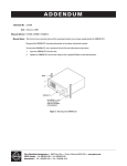
ADDENDUM
Addendum No.:
Date:
Manuals Affected:
Manual Update:
C1577M-A
August 4, 2004
CM9760 Series Manuals – C538M-A, C539M-A, C540M-B, C541M-C, C542M-B,
C543M-A, C544M, C549M-A, C572M, C573M-D, C578M, C579M, C1501M, C1503M,
C1510M-QS, C1510M-A, C1520M-B, C1528M-D, C1940M, C1941M, C1942M, and
C1943M
The CM9760-CC1 has been replaced with the CM9700-CC1 and the CM9760-MGR management software has been replaced with the CM9700-MGR management software.
Keep the following in mind when referring to the instructions contained in these manuals:
•
The CM9700-CC1 contains the latest CC1 software (version 9.01 or higher), and is
programmed with the new CM9700-MGR management software.
•
Despite the difference in model numbers, the CM9700-CC1 functions the same as the
CM9760-CC1 and most of the information in these manuals applies to version 9.01 (or
higher) CPU.
•
You can add the CM9700-CC1 to an existing CM9760 system if you upgrade the existing
CM9760-CC1 units with the current software (version level 9.01 or higher).
Software version 9.01 requires a minimum of 16 MB of RAM in the CPU. If required, you
can upgrade the RAM in older CM9760-CC1 units using the software upgrade kit
appropriate for your CPU.
•
®
Do not use the CM9760-MGR instructions contained in these manuals. Refer to the
CM9700-MGR Getting Started Software Guide, on-screen help, or Online Help for
instructions.
Pelco World Headquarters • 3500 Pelco Way, Clovis, California 93612-5699 USA • www.pelco.com
USA & Canada: Tel: 800/289-9100 • Fax: 800/289-9150
International: Tel: 1-559/292-1981 • Fax: 1-559/348-1120
®
CM9760-REL
System 9760®
Relay Interface Unit
Installation/
Operation Manual
C538M-A (3/04)
Pelco World Headquarters • 3500 Pelco Way, Clovis, CA 93612-5699 USA • www.pelco.com
USA & Canada: Tel: 800/289-9100 • Fax: 800/289-9150
International: Tel: 1-559/292-1981 • Fax: 1-559/348-1120
CONTENTS
Section
Page
1.0 GENERAL ................................................................................................... 3
1.1 IMPORTANT SAFEGUARDS AND WARNINGS ................................ 3
2.0 DESCRIPTION ........................................................................................... 4
2.1 MODELS ............................................................................................ 4
3.0 PRE-INSTALLATION INFORMATION ......................................................... 5
3.1 FRONT VIEW AND DIP SWITCH ACCESS ....................................... 5
3.1.1 DIP Switches .......................................................................... 5
3.1.2 LEDs ....................................................................................... 5
3.2 REAR VIEW ........................................................................................ 6
3.2.1 REL Contact Pair Connections ............................................... 7
3.2.2 External Relay Wiring Considerations .................................... 8
3.2.3 Communication Connectors ................................................... 8
3.2.3.1
DB-9 Connector ..................................................... 8
3.2.3.2
RJ-45 Data Cables ................................................. 9
3.2.4 Power Connections ............................................................... 10
3.3 SETUP ............................................................................................... 11
3.3.1 Preliminary Discussion .......................................................... 11
3.3.2 DIP Switch Settings ............................................................... 13
3.3.3 Software Considerations ....................................................... 16
4.0 INSTALLATION .......................................................................................... 17
4.1 DIRECT RACK-MOUNT HOOK-UP .................................................. 17
4.2 REMOTE OPERATION ...................................................................... 17
4.3 DAISY-CHAINING .............................................................................. 18
5.0 OPERATION .............................................................................................. 19
5.1 OPERATIONAL OVERVIEW ............................................................. 19
5.2 OPERATING THE CM9760-REL FROM THE CM9760-KBD ............ 19
5.2.1 Information Retrieval ............................................................. 19
5.2.2 Keyboard Operation .............................................................. 21
6.0 SPECIFICATIONS ..................................................................................... 23
7.0 WARRANTY AND RETURN INFORMATION ............................................ 24
LIST OF ILLUSTRATIONS
Figure
1
2
3
4
5
6
7
8
9
10
11
12
13
14
15
16
Page
Front View with Panel Removal ............................................................ 5
Rear View of the CM9760-REL ............................................................ 6
Relay Interface Contact Configuration .................................................. 7
External Relay Wiring ........................................................................... 8
RJ-45 Pin-outs ...................................................................................... 9
RJ-45 Cable Types ............................................................................... 9
Power Input Fuse Replacement .......................................................... 10
Relationship of Frame Address Space and the Relay Interface Unit ... 11
Relationship of Frame Address Space with Respect to Starting
Address and the Relay Interface Units ................................................ 12
DIP Switch Functions .......................................................................... 13
Configuring the GPI Define File for REL Operation ............................. 16
Configuring the COMMS File for REL Operation ................................ 16
Unit Dimensions and Rack-Mount Installation ..................................... 17
Relay Unit Daisy-Chain Configuration ................................................. 18
Physical Representation of Figure 16 ............................................... 20
Controlling REL Output Contacts From the CM9760-KBD ............... 22
LIST OF TABLES
Table
A
2
Page
Frame Address, GPI Range Association .......................................... 14
Pelco Manual C538M-A (3/04)
1.0 GENERAL
1.1 IMPORTANT SAFEGUARDS AND WARNINGS
Prior to installation and use of this product, the following WARNINGS should be
observed.
1.
Installation and servicing should only be done by qualified service personnel
and conform to all local codes.
2.
Unless the unit is specifically marked as a NEMA Type 3, 3R, 3S, 4, 4X ,6 or
6P enclosure, it is designed for indoor use only and it must not be installed
where exposed to rain and moisture.
3.
Only use replacement parts recommended by Pelco.
4.
After replacement/repair of this unit’s electrical components, conduct a resistance measurement between line and exposed parts to verify the exposed
parts have not been connected to line circuitry.
The product and/or manual may bear the following marks:
This symbol indicates that dangerous voltage constituting a
risk of electric shock is present within this unit.
This symbol indicates that there are important operating and
maintenance instructions in the literature accompanying this
unit.
CAUTION:
RISK OF
ELECTRIC SHOCK.
DO NOT OPEN.
CAUTION:
TO REDUCE THE RISK OF ELECTRICAL SHOCK,
DO NOT REMOVE COVER. NO USERSERVICEABLE PARTS INSIDE. REFER SERVICING
TO QUALIFIED SERVICE PERSONNEL.
Please thoroughly familiarize yourself with the information
in this manual prior to installation and operation.
Pelco Manual C538M-A (3/04)
3
2.0 DESCRIPTION
The CM9760-REL Relay Interface Unit is an optional accessory of the System 9760®.
The relay interface unit provides dry contact switching for direct or automatic control of peripheral equipment. The unit connects to any RS-422 COMM port on the
rear of the CM9760-CC1.
Some of the more important features of the CM9760-REL are as follows:
•
Each unit provides up to 64 single-pole, single-throw (SPST) contact outputs
for operating different peripheral equipment.
•
Relay output contacts may be configured for N/O (factory default) or N/C operation.
•
With a handy “memory” feature, relay groups can retain or hold their pre-power
loss contact position in the event of a power failure or front panel reset.
•
Multiple units may be cascaded to extend the number of relay contact outputs
controlled from a single port on the CC1 (over 5,000 relay outputs can be
configured).
•
The relay unit may be remotely placed up to 4,000 feet (1,219.2 meters) from
the controller (RS-422 operation).
•
The unit is powered by an auto-ranging power supply.
•
The unit is a unique, one rack unit chassis (1.75 inches or 4.45 cm) accommodating multiple types of mounting.
2.1 MODELS
CM9760-REL
4
Single relay unit capable of controlling up to 64 relay contact
outputs per unit. (CE)
Pelco Manual C538M-A (3/04)
3.0 PRE-INSTALLATION INFORMATION
3.1 FRONT VIEW AND DIP SWITCH ACCESS
Figure 1 illustrates a front view of the unit with its front panel removed. Power (green)
and Data (red) LEDs occupy opposite ends of the unit’s front panel. As illustrated,
the removal of the five flat-head Phillips screws that hold the front panel in place
allow access to the units three DIP switches and the reset switch. All other switches
and connectors are on the rear of the unit.
3.1.1 DIP Switches
The relay interface unit has three 10-position DIP switches that configure the communication parameters for the unit as well setting the parameters for relay contact
output operation. DIP switch functions are discussed in Section 3.3.2, DIP Switch
Settings.
3.1.2 LEDs
The green POWER LED located on the left side of the front panel of the unit comes
ON at power up.
The red DATA LED located on the right side of the front panel continually flashes on
and off at a regular rate (about 1/2 second intervals) until the first valid command is
received. The LED will not flash again until another valid command is received. In
cascaded configurations, each relay unit only indicates receiving data when the
data has the corresponding address of the unit. In other words, LED activity is
address specific.
In addition, if power is cycled, if a DIP switch slide switch position is moved, or if a
front panel reset occurs, the LED will again flash intermittently until the first valid
command is received.
Figure 1. Front View with Panel Removal
Pelco Manual C538M-A (3/04)
5
3.2 REAR VIEW
The rear of the unit is illustrated in Figure 2. From left to right are the following:
1.
Four blocks consisting of 16 contact pairs, each with mating plugs for the attachment of peripheral equipment. (Only the block for the first 16 contact pairs
is shown with mating plugs.)
2.
RS-422 input/output communication connectors (RJ-45 type).
3.
One DB-9 connector (factory use only).
4.
The grouped input power functions, consisting of input power terminals, a fuse
and an ON/OFF switch.
Figure 2. Rear View of the CM9760-REL
6
Pelco Manual C538M-A (3/04)
3.2.1 REL Contact Pair Connections
NOTE: The numbers that appear
on the mating plugs in Figure 3 are
placed there for explanatory purposes only. The terminal positions
on the actual physical plugs are not
numbered.
Physically, each relay block consists of 16 relay contacts and two mating plugs.
Since a relay contact requires two terminal positions, each plug provides 8 contacts
via 16 screw terminals.
To determine the screw terminal pin numbers for a particular contact, refer to
Figure 3.
Figure 3. Relay Interface Contact Configuration
Pelco Manual C538M-A (3/04)
7
3.2.2 External Relay Wiring Considerations
Components of external relay wiring are illustrated in Figure 4.
3.2.3 Communication Connectors
Communication to and from the unit is provided through two RJ-45 ports on the
rear of the CM9760-REL. The ports are physically referenced as IN and OUT ports.
The RJ-45 IN connector allows the REL unit to be connected to an appropriate
Sercom port on the rear of a CM9760-CC1 controller. This port is factory set for
RS-422 communications.
The RJ-45 OUT female connector on the rear of the unit is always configured for
RS-422 and is used for cascading subsequent REL units.
The RJ-45 connector pin-outs are illustrated in Figure 5.
3.2.3.1 DB-9 Connector
The rear panel DB-9 connector (factory use only).
32°-122°F (0°-50°C)
+
–
Figure 4. External Relay Wiring
8
Pelco Manual C538M-A (3/04)
3.2.3.2 RJ-45 Data Cables
NOTE: Use the supplied “flipped”
or reverse cable for all data connections to the relay unit whenever
possible.
Because both RJ-45 connectors have the same wiring pin-outs, they require the
same “flipped” cable. In other words, the IN connector requires a “flipped” cable for
connecting the first unit to the CC1, and the OUT connector requires a “flipped”
cable for cascading other units. A “flipped” cable is as follows: Pin 1 of the cable at
one end becomes pin 8 at the other end. Refer to Figure 6.
Note that the active pin-outs are associated with the outer four pins; namely, 1, 2, 7,
and 8. All accessories on the System 9760 require that the “flipped” cable be used
to attach peripheral equipment. This includes the REL unit.
NOTE REVERSE OR “FLIPPED” CABLE
Figure 5. RJ-45 Pin-outs
Figure 6. RJ-45 Cable Types
Pelco Manual C538M-A (3/04)
9
3.2.4 Power Connections
The CM9760-REL utilizes an auto-ranging internal transformer circuit that allows
input power to range from 100-240 VAC, 50/60Hz. Associated with the input power
is the power ON/OFF switch and the input power fuse. The fuse is easily changed
as illustrated in Figure 7.
Figure 7. Power Input Fuse Replacement
10
Pelco Manual C538M-A (3/04)
3.3 SETUP
3.3.1 Preliminary Discussion
NOTE: At present, 700 GPIs are
available per system node. This
limit must be kept in mind when
configuring cascaded systems.
Some devices utilize more GPIs
and therefore more Frame Address
Space than other devices.
NOTE: Only one device type at a
time can utilize the same frame
start address.
FRAME ADDRESSES
The IRC, VCRC, and the CM9760-REL Relay Interface Unit, all use software GPIs
to activate control of external devices.
The number of GPIs required by each hardware device varies. The number of GPIs
(General Purpose Interfaces) required by the REL is eight.
The address setting entered into the DIP switches, however, is based on what is
called a frame address.
There is a direct numerical relationship between GPIs and frame addressing, which
is as follows:
THE USE OF 32 GPIs SPANS ONE FRAME ADDRESS, REGARDLESS OF DEVICE TYPE USED (device types other than REL units also utilize GPI control).
Therefore a single REL, which uses eight GPIs, occupies only 1/4 of a frame address (refer to Figure 8).
This means that four relay units fit into one frame address space. To uniquely identify and address REL units within this frame address space, two additional address
bits (sub-frame bits) are used (refer to Figure 10).
The frame address entered in the DIP switch for the REL (or any other device)
serves as a STARTING point for the frame address space it needs. Once a starting
frame address is entered, the REL can be thought of as allocating for itself the next
eight GPIs or the equivalent 1/4 frame address space it needs to operate. The REL,
of course, is unique in that when you have any grouping of REL units totaling four or
less, they will all more than likely share the SAME FRAME ADDRESS, and differ
only in their SUB-FRAME address bit settings.
ADDITIONAL REMARKS REGARDING FRAME ADDRESSES AND GPIs
Figure 8. Relationship of Frame
Address Space and
the Relay Interface
Unit
One frame address is equivalent to the use of 32 GPIs. With a total of only 700 GPIs
available, only 700/32 or 21.8 (rounded up to 22) frame addresses are needed.
Frame addressing starts at “0”, so frame addressing runs from 0 to 21, or 22 total.
The layout of all 22 frame addresses and corresponding GPI ranges can be found
in Table A.
THE RELAY INTERFACE MEMORY FUNCTION
SW3 DIP switch settings (SW3-3 through SW3-6) control what can be thought of
as the contact “memory” function for the REL unit.
One would normally expect that when power is cycled (via a power failure or front
panel reset) that the relay contacts would return to their default settings, which for
the REL, would be determined by the normally open, normally closed (N/O, N/C)
settings entered into DIP switch 2 (SW2-7 through SW2-10).
The additional DIP switch settings for the memory function allow you to override the
default setting in the event power is cycled. With a switch setting of “1” (memory
enabled), the contacts (in groups of 16) will retain the contact setting they had at
the time power was cycled. For groups not enabled, the contacts will defer to their
default values (per DIP switch 2 settings) if power is cycled (refer to Figure 10).
Pelco Manual C538M-A (3/04)
11
NOTE: Figure 9 does not necessarily represent the order in which
REL units are physically connected together (for that, refer to
Figure 14).
Figure 9 does illustrate that frame
address settings:
(1) Must be unique for each unit.
(2) Must follow the working rules
listed.
When setting frame addresses on the front panel switches for a group of daisychained REL units, keep in mind a few working rules:
WORKING RULES
1.
Start with frame address 0, which is associated with physical GPI 1, and work
sequentially forward until all relay interface units are accounted for. Insure that
frame address space is contiguous (see EXAMPLE ONE and TWO of Figure 9).
2.
The physical order in which relay units are connected is irrelevant. In a cascaded situation, however, leftover REL combinations using less than one frame
address space should be placed at the tail-end of allocated frame address
space.
3.
Do not overlap frame address spaces (see EXAMPLE FOUR in Figure 9).
4.
Do not leave any open frame address spaces in the layout (see EXAMPLE
THREE in Figure 9).
For explanatory purposes, the setup in Figure 9 is used again in other parts of
the manual to illustrate various aspects of REL configuration and setup.
EACH BOX REPRESENTS THE
FRAME ADDRESS SPACE
(EIGHT GPIs) USED BY ONE
REL UNIT.
SUBFRAME
FRAME
ADDRESS ADDRESS
3
2
1
0
3
2
1
0
3
2
1
0
3
2
1
0
3
2
1
0
3
2
1
0
OK
UNIT REFERENCE:
ONE FRAME ADDRESS
SPACE SPANS 32 GPIs
ADDRESS SPACING
GAPS NOT ALLOWED
FRAME ADDRESS
OVERLAP NOT
ALLOWED
Figure 9. Relationship of Frame Address Space with Respect to
Starting Address and the Relay Interface Units
12
Pelco Manual C538M-A (3/04)
3.3.2 DIP Switch Settings
DIP switch settings are illustrated and discussed in Figure 10.
Figure 10. DIP Switch Functions
Pelco Manual C538M-A (3/04)
13
Table A. Frame Address, GPI Range Association
Daisy-Chained
Relay Units
Running Total
Frame
Addresses
SW2
1 2 3 4 5
Sub-Frame
Addresses
SW3
1
2
Combined
Frame/Sub-Frame
Addresses
FA/SFA
6
1
0 0 0
0
0
0
0
2
0 0 0
0
0
0
3
0 0 0
0
0
0
4
0 0 0
0
0
5
1 0 0
0
6
1 0 0
0
7
1 0 0
8
Associated GPI Range
Eight Required GPI #’s Associated
with a Frame/Sub-Frame Address
2
3
4
5
6
7
8
1
0
00
1
1
0
01
9
10
11
12
13
14
15
16
0
1
02
17
18
19
20
21
22
23
24
0
1
1
03
25
26
27
28
29
30
31
32
0
0
0
0
10
33
34
35
36
37
38
39
40
0
0
1
0
11
41
42
43
44
45
46
47
48
0
0
0
0
1
12
49
50
51
52
53
54
55
56
1 0 0
0
0
0
1
1
13
57
58
59
60
61
62
63
64
2
3
4
5
6
7
8
9
0 1 0
0
0
0
0
0
20
65
66
67
68
69
70
71
72
10
0 1 0
0
0
0
1
0
21
73
74
75
76
77
78
79
80
11
0 1 0
0
0
0
0
1
22
81
82
83
84
85
86
87
88
12
0 1 0
0
0
0
1
1
23
89
90
91
92
93
94
95
96
13
1 1 0
0
0
0
0
0
30
97
98
99
100
101
102
103 104
14
1 1 0
0
0
0
1
0
31
105
106
107
108
109
110
111 112
15
1 1 0
0
0
0
0
1
32
113
114
115
116
117
118
119 120
16
1 1 0
0
0
0
1
1
33
121
122
123
124
125
126
127 128
17
0 0 1
0
0
0
0
0
40
129
130
131
132
133
134
135 136
18
0 0 1
0
0
0
1
0
41
137
138
139
140
141
142
143 144
19
0 0 1
0
0
0
0
1
42
145
146
147
148
149
150
151 152
20
0 0 1
0
0
0
1
1
43
153
154
155
156
157
158
159 160
21
1 0 1
0
0
0
0
0
50
161
162
163
164
165
166
167 168
22
1 0 1
0
0
0
1
0
51
169
170
171
172
173
174
175 176
23
1 0 1
0
0
0
0
1
52
177
178
179
180
181
182
183 184
24
1 0 1
0
0
0
1
1
53
185
186
187
188
189
190
191 192
25
0 1 1
0
0
0
0
0
60
193
194
195
196
197
198
199 200
26
0 1 1
0
0
0
1
0
61
201
202
203
204
205
206
207 208
27
0 1 1
0
0
0
0
1
62
209
210
211
212
213
214
215 216
28
0 1 1
0
0
0
1
1
63
217
218
219
220
221
222
223 224
29
1 1 1
0
0
0
0
0
70
225
226
227
228
229
230
231 232
30
1 1 1
0
0
0
1
0
71
233
234
235
236
237
238
239 240
31
1 1 1
0
0
0
0
1
72
241
242
243
244
245
246
247 248
32
1 1 1
0
0
0
1
1
73
249
250
251
252
253
254
255 256
33
0 0 0
1
0
0
0
0
80
257
258
259
260
261
262
263 264
34
0 0 0
1
0
0
1
0
81
265
266
267
268
269
270
271 272
35
0 0 0
1
0
0
0
1
82
273
274
275
276
277
278
279 280
36
0 0 0
1
0
0
1
1
83
281
282
283
284
285
286
287 288
37
1 0 0
1
0
0
0
0
90
289
290
291
292
293
294
295 296
38
1 0 0
1
0
0
1
0
91
297
298
299
300
301
302
303 304
39
1 0 0
1
0
0
0
1
92
305
306
307
308
309
310
311 312
40
1 0 0
1
0
0
1
1
93
313
314
315
316
317
318
319 320
41
0 1 0
1
0
0
0
0
100
321
322
323
324
325
326
327 328
42
0 1 0
1
0
0
1
0
101
329
330
331
332
333
334
335 336
43
0 1 0
1
0
0
0
1
102
337
338
339
340
341
342
343 344
44
0 1 0
1
0
0
1
1
103
345
346
347
348
349
350
351 352
(Continued on next page)
14
Pelco Manual C538M-A (3/04)
Table A. Frame Address, GPI Range Association (Continued)
Daisy-Chained
Relay Units
Running Total
Frame
Addresses
SW2
1 2 3 4 5
Combined
Frame/Sub-Frame
Addresses
FA/SFA
6
45
1 1 0
1
0
0
0
1
0
110
353
46
1 1 0
1
0
0
354
355
356
357
358
359 360
1
0
111
361
362
363
364
365
366
47
1 1 0
1
0
367 368
0
0
1
112
369
370
371
372
373
374
375 376
48
1 1 0
1
49
0 0 1
1
0
0
1
1
113
377
378
379
380
381
382
383 384
0
0
0
0
120
385
386
387
388
389
390
50
0 0 1
391 392
1
0
0
1
0
121
393
394
395
396
397
398
399 400
51
52
0 0 1
1
0
0
0
1
122
401
402
403
404
405
406
407 408
0 0 1
1
0
0
1
1
123
409
410
411
412
413
414
415 416
53
1 0 1
1
0
0
0
0
130
417
418
419
420
421
422
423 424
54
1 0 1
1
0
0
1
0
131
425
426
427
428
429
430
431 432
55
1 0 1
1
0
0
0
1
132
433
434
435
436
437
438
439 440
56
1 0 1
1
0
0
1
1
133
441
442
443
444
445
446
447 448
57
0 1 1
1
0
0
0
0
140
449
450
451
452
453
454
455 456
58
0 1 1
1
0
0
1
0
141
457
458
459
460
461
462
463 464
59
0 1 1
1
0
0
0
1
142
465
466
467
468
469
470
471 472
60
0 1 1
1
0
0
1
1
143
473
474
475
476
477
478
479 480
61
1 1 1
1
0
0
0
0
150
481
482
483
484
485
486
487 488
62
1 1 1
1
0
0
1
0
151
489
490
491
492
493
494
495 496
63
1 1 1
1
0
0
0
1
152
497
498
499
500
501
502
503 504
64
1 1 1
1
0
0
1
1
153
505
506
507
508
509
510
511 512
65
0 0 0
0
1
0
0
0
160
513
514
515
516
517
518
519 520
66
0 0 0
0
1
0
1
0
161
521
522
523
524
525
526
527 528
67
0 0 0
0
1
0
0
1
162
529
530
531
532
533
534
535 536
68
0 0 0
0
1
0
1
1
163
537
538
539
540
541
542
543 544
69
1 0 0
0
1
0
0
0
170
545
546
547
548
549
550
551 552
70
1 0 0
0
1
0
1
0
171
553
554
555
556
557
558
559 560
71
1 0 0
0
1
0
0
1
172
561
562
563
564
565
566
567 568
72
1 0 0
0
1
0
1
1
173
569
570
571
572
573
574
575 576
73
0 1 0
0
1
0
0
0
180
577
578
579
580
581
582
583 584
74
0 1 0
0
1
0
1
0
181
585
586
587
588
589
590
591 592
75
0 1 0
0
1
0
0
1
182
593
594
595
596
597
598
599 600
76
0 1 0
0
1
0
1
1
183
601
602
603
604
605
606
607 608
77
1 1 0
0
1
0
0
0
190
609
610
611
612
613
614
615 616
78
1 1 0
0
1
0
1
0
191
617
618
619
620
621
622
623 624
79
1 1 0
0
1
0
0
1
192
625
626
627
628
629
630
631 632
80
1 1 0
0
1
0
1
1
193
633
634
635
636
637
638
639 640
81
0 0 1
0
1
0
0
0
200
641
642
643
644
645
646
647 648
82
0 0 1
0
1
0
1
0
201
649
650
651
652
653
654
655 656
83
0 0 1
0
1
0
0
1
202
657
658
659
660
661
662
663 664
84
0 0 1
0
1
0
1
1
203
665
666
667
668
669
670
671 672
85
1 0 1
0
1
0
0
0
210
673
674
675
676
677
678
679 680
86
1 0 1
0
1
0
1
0
211
681
682
683
684
685
686
687 688
87
1 0 1
0
1
0
0
1
212
689
690
691
692
693
694
695 696
88
1 0 1
0
1
0
1
1
213
697
698
699
700
701
702
703 704
Pelco Manual C538M-A (3/04)
Sub-Frame
Addresses
SW3
1
2
Associated GPI Range
Eight Required GPI #’s Associated
with a Frame/Sub-Frame Address
2
3
4
5
6
7
8
15
3.3.3 Software Considerations
NOTE: When writing macros to
control REL operation, keep in
mind the following:
The macro must reflect your actual
equipment configuration; if you
change the configuration, you must
adjust the macro accordingly. For
example, if a macro were written
to control three RELs in a daisychain configuration and one of the
RELs was subsequently removed,
then any previously written macro
that included these three RELs
would have to be rewritten to reflect that change. Similarly, changing the frame address setting of
any of the RELs is essentially the
same as physically removing it
from the configuration.
Access to the operation of specific devices connected to REL units using keyboards
commands or macro operations depends on the GPI and the specific GPI ranges
each REL unit is assigned. For this to be possible, the software GPI Define File
must be configured using the MGR program. What follows is a brief introduction to
the configuration of the GPI and COMM setup files that need to be programmed for
successful REL operation. This introduction may not address other items that might
be needed for your particular system operation. Consult your MGR manual and
associated software for other specific or detailed information.
On a PC and monitor containing the 9760 MGR setup program, start the program
and access the GPI File (GPI file). Refer to Figure 11.
Each GPI can control up to eight relays; we therefore need to configure eight GPIs
to control the 64 relays on one REL unit.
1.
Program the logical GPI numbers for all the physical GPI numbers that will be
used. In most cases it is advisable to program the logical number to be equal
to the existing physical GPI number.
2.
For each associated GPI defined, configure individual relays as momentary or
latching, depending on the application.
R1 R2 R3
Latching ✓
R8
✓ ...✓
If the box is checked, it is latching; otherwise it is mometary (refer to Figure 11).
3.
Define operator access, save the GPI file, return to the MGR main menu screen
and press the tab to bring up the COMMS file (.SCP file). Refer to Figure 12.
4.
In the COMMs file, assign an equipment number (PIN) of 17 to the port on the
CC1 that will be used for communicating with the REL. Set the communication
settings for 9600 baud and even parity. Save the COMMs file, back out of the
MGR program and transfer all appropriate configuration files to disk and load
these files onto the CC1 to which your REL configuration is attached. You
should now be ready to operate your REL via direct control from the CM9760KBD. For manual or automatic control of REL functions under macro control,
consult the appropriate sections of the MGR manual.
R1, R2...R8 CONFIGURED AS
MOMENTARY OR LATCHING
(DEPENDING ON APPLICATION)
Figure 11. Configuring the GPI Define File for
REL Operation
16
Figure 12. Configuring the COMMS File for
REL Operation
Pelco Manual C538M-A (3/04)
4.0 INSTALLATION
Physical installation of the REL unit is relatively simple, although various configurations are possible.
4.1 DIRECT RACK-MOUNT HOOK-UP
The REL unit mounts in a standard 19-inch rack and occupies only one RU (1.75"
or 4.45 cm) of rack space (refer to Figure 13).
4.2 REMOTE OPERATION
The relay unit may be mounted to something other than a standard 19-inch rack by
relocating the rack ears to another position. If it is desired to place the REL unit
some distance from the controller (CM9760-CC1), the RS-422 communications
from the relay unit to the controller should not exceed 4,000 feet (1,219 m).
Figure 13. Unit Dimensions and Rack-Mount Installation
Pelco Manual C538M-A (3/04)
17
4.3 DAISY-CHAINING
Daisy-chaining occurs when more than 64 relays are required.
More importantly, each unit must be configured to have a unique address, referred
to as a Frame Address. Frame addressing with respect to REL units was discussed
in Section 3.3.1. What follows is a discussion about the physical hook-up of multiple
REL units. System software supports up to 700 GPIs or 5,600 relays. Whether
daisy-chaining two or multiple REL units, the first unit is connected from its “IN”
connector to the CC1 and connected to the second unit through its “OUT” connector. Subsequent units are chained together in the same way.
NOTE: Since VCRC units also utilize GPI addressing, they can be
bussed together with REL units.
Figure 14 illustrates the physical hook-up of two cascaded configurations, each
containing nine REL units having the frame addresses illustrated in Figure 9.
Note that the physical order that any unit has in the configuration is independent of
its frame/sub-frame address.
Also note that the remarks made in the previous section regarding RS-422 wiring
run distances applies here when considering cables distance runs between daisychained units.
THE DIAGRAM BELOW DEPICTS VALID PHYSICAL HOOKUP VARIATIONS
OF THE SETUP DISCUSSED IN FIGURE 9 (MANY OTHERS ARE POSSIBLE).
SINCE EACH UNIT HAS A UNIQUE ADDRESS, IT MAKES NO DIFFERENCE
WHERE, IN THE CASCADED CHAIN, A PARTICULAR UNIT IS LOCATED.
HOOK-UP (1) AND (2) BELOW DIFFER PHYSICALLY, BUT ARE OPERATIONALLY
THE SAME (SEE NOTE).
SWAPPED OR REVERSE CABLES
(REFER TO SECTION ON COMMUNICATION CONNECTORS)
(1)
(2)
NOTE: PHYSICAL LOCATION OF REL 9 IN (2) IS DIFFERENT THAN REL 9 IN (1),
BUT OPERATIONALLY THE SAME BECAUSE THE FRAME ADDRESS HAS
NOT CHANGED.
Figure 14. Relay Unit Daisy-Chain Configuration
18
Pelco Manual C538M-A (3/04)
5.0 OPERATION
5.1 OPERATIONAL OVERVIEW
The basic function of the REL unit is to allow the user/operator to control various
peripheral equipment via relay contacts. Each REL unit processes and executes
only commands with addresses that match that of the RELs (frame address). When
an REL receives a command with an inappropriate address, it passes it on to the
next unit (if applicable) via its OUT port.
When power is first applied to the unit, RAM is cleared and initialization routines
are called. The power LED is lit, operational chips are configured, interrupt priorities are set and the Data LED starts flashing on and off at about 1/2 second
intervals (refer to Section 3.1.2, LEDs). The unit is waiting for its first valid command.
5.2 OPERATING THE CM9760-REL FROM THE CM9760-KBD
Direct control operation of peripherals attached to RELs from a CM9760-KBD is
relatively straightforward once you have determined which GPI to call and AUX to
activate. In the next section, we discuss two methods for obtaining this information.
Method 1 uses Figure 16 and Table A; Method II uses the CM9760-REL GPI/AUX
CALCULATOR only (ignore VCRC references on the backside of the calculator).
5.2.1 Information Retrieval
OUR EXAMPLE: Assume you have five cascaded REL units and you wish to activate the peripheral device attached to relay 39 on REL unit 5.
What information do you need to know?
Where can you find the information?
First, you need to determine two things:
1.
Which GPI to call of the 704 available.
2.
Which AUX, associated with the GPI, to press.
Method I – Table A and Figure 15
Figure 15 is a physical representation of OUR EXAMPLE. We will also use it to
recap the information needed to perform the steps illustrated in Figure 16.
First, the GPI range. Every REL unit is associated with a range of eight GPIs. In our
sequential run of cascaded units, REL 5 has a GPI range of 33-40. (Had we instead
been interested in REL unit 1, then the GPI range we would want would be 1-8).
The GPI range can be determined in a number of ways: (1) you may already have a
list or (2), you can match the frame/sub-frame address on the physical REL unit
with those listed in Table A and thus find the GPI range and (3), if you already know
the frame/sub-frame address, you can use Table A alone.
Starting on the left in Figure 15, you can follow the line to the right of GPI 37 over to
where it intersects with the AUX associated with relay grouping 33-40. GPI 37,
therefore, is the specific GPI we need to accomplish our task. Of eight AUX associated with GPI 37, we can see that AUX 7 is the one we need. Follow the vertical line
from AUX 7 up to where it intersects the associated relay numbers and you will find
number 39.
Pelco Manual C538M-A (3/04)
19
Figure 15. Physical Representation of Figure 16
20
Pelco Manual C538M-A (3/04)
GPI
RANGE
FOR
REL UNIT 5
ASSOCIATED
AUX
ASSOCIATED AUX
REL UNIT 1
ASSOCIATED AUX
PERIPHERAL
DEVICES
REL UNIT 3
ASSOCIATED AUX
PERIPHERAL
DEVICES
ASSOCIATED AUX
REL UNIT 2
ASSOCIATED AUX
PERIPHERAL
DEVICES
REL UNIT 5
ASSOCIATED AUX
PERIPHERAL
DEVICES
ASSOCIATED AUX
REL UNIT 4
PERIPHERAL
EQUIPMENT
Method II – The CM9760-GPI/AUX Calculator
If we revisit the EXAMPLE just discussed and illustrated in Figures 15, we can
immediately find the information needed by direct read-off from the information
boxes on the front of the calculator.
Move the calculator wheel until the number “five” appears in the Relay Unit # box.
Go to the table to the right of that and locate relay 39 in the yellow highlighted box;
travel to the left along that row and read off GPI 37 on the GPI Range slot. Next,
read off the AUX needed by looking at the Associated Aux row and locate the Aux #
directly above 39. You now have the information needed (call GPI 37, press AUX 7)
to operate the desired relay from the 9760-KBD. Once the GPI and AUX information
is at hand, control from the keyboard is easy. (Refer to Section 5.2.2, KEYBOARD
OPERATION.)
Other Operations Using the Calculator
The CM9760-GPI/AUX Calculator comes in handy for operations other than obtaining the information needed for direct keyboard control operations.
Other uses might include the following:
1.
As a reference for setting frame/sub-frame address switches when installing a
group of cascaded REL units in a system installation. Just display each Relay
Unit # in the order it is installed (1-5, say) and at each setting of the wheel,
read off the frame/sub-frame Dip Switch readings and set the corresponding
switches on the REL unit itself.
2.
If you need to know the GPI range of a particular unit, move the wheel until the
unit’s DIP switch settings match those that appear in the calculator’s frame/
sub-frame address boxes. Directly read off the GPI range for the given REL
unit.
3.
Check on the validity of a GPI call.
4.
Use the wheel while programming GPI and other related files to double-check
the relationship of the GPIs being defined with respect to the relay actually
being set up for use on which unit.
5. As an information source in troubleshooting situations.
5.2.2 Keyboard Operation
Using the specific GPI/AUX information obtained via Method I or Method II, it is
possible to control the desired peripheral device from the CM9760-KBD.
Below are listed the steps needed to utilize this information for direct control operation from the 9760 keyboard.
Pelco Manual C538M-A (3/04)
21
Once the system is running and a keyboard is on-line, direct control of an REL is as
follows (refer to Figure 16):
NOTE: Figure 16 uses the setup
configuration of Figure 9 to illustrate
the steps involved to activate relay
39 output on REL unit 5.
1.
From the Default menu, use the keyboard keypad to enter the GPI number
that contains the relay output you wish to activate (data obtained via Method I
or Method II).
2.
After entering the desired number, press the GPI button to bring up the GPI
sub-menu.
3.
The GPI sub-menu shows the first six of eight auxiliary function icons, corresponding to six relays associated with the selected GPI. Press the MORE
button to see the remaining two.
4.
Press the appropriate AUX function button directly below the desired Aux icon
to activate the relay and associated peripheral device.
5.
Repeat steps 1 through 4 to control additional devices.
Figure 16. Controlling REL Output Contacts From the CM9760-KBD
22
Pelco Manual C538M-A (3/04)
6.0 SPECIFICATIONS
ELECTRICAL
REL UNIT RELAY CONTACTS**
Parameters:
Maximum Switching Capacity
Maximum Operating Voltage
Maximum Current
Contact Resistance
Rated Load
Parameters:
.5A @ 125 VAC
2A @ 30 VDC
60 Watts
125V AC/DC
2 Amps
75 m ohms
REL UNIT
Input Voltage:
Auto-ranging 100-240 VAC 50/60 Hz
Power:
Consumption: 30 vA, 5 watts
Data Ports
Input:
Output:
RS-422, RJ-45 connector
DIP switch selectable baud-rate.
RS-422, RJ-45 connector.
DIP switch selectable baud rate
Output:
RS-232, DB-9 connector
Indicators:
2 power LEDs, green
1 data LED, red
Fusing:
500 mA, 250V
GENERAL
Dimensions:
17.4" W x 1.73" H x 8.54" D (44.2 cm x 4.39 cm x 21.69 cm)
Operating
Temperature:
32°F to 122°F (0°C to 50°C)
Weight:
8 lb (3.63 kg)
MECHANICAL
Connectors
REL Input:
Power:
RS422:
RS-232:
Relay out:
Four dual-header, 32 input connectors with mating plugs
3-wire, #18 AWG
Two RJ-45 connectors
One DB-9 connector (factory use only)
One 3-pin header with mating plug
** For information regarding additional specified, known parameters, refer to specification sheets for relay type G6SK-2F-H from OMRON, if necessary.
(Design and product specifications subject to change without notice.)
Pelco Manual C538M-A (3/04)
23
7.0 WARRANTY AND RETURN INFORMATION
WARRANTY
Pelco will repair or replace, without charge, any merchandise proved defective in material or workmanship for a period of one year after the date
of shipment. Exceptions to this warranty are as noted below:
If a warranty repair is required, the Dealer must contact Pelco at
(800) 289-9100 or (559) 292-1981 to obtain a Repair Authorization number (RA), and provide the following information:
• Five years on Pelco manufactured cameras (CC3500/CC3600/CC3700
and MC3500/MC3600/MC3700 Series); two years on all other cameras.
1. Model and serial number
2. Date of shipment, P.O. number, Sales Order number, or Pelco invoice
number
3. Details of the defect or problem
• Three years on Genex® Series (multiplexers, server, and keyboard)
and 090 Series Camclosure® Camera System.
• Two years on 100/150, 200 and 300 Series Camclosure® Camera Systems.
• Two years on cameras and all standard motorized or fixed focal length
lenses.
If there is a dispute regarding the warranty of a product which does not fall
under the warranty conditions stated above, please include a written explanation with the product when returned.
Method of return shipment shall be the same or equal to the method by
which the item was received by Pelco.
®
• Two years on Legacy , CM6700/CM6800/CM6800E/CM8500/CM9500/
CM9740/CM9760 Matrix, DF5 and DF8 Series Fixed Dome products.
• Two years on Spectra®, Esprit®, and PS20 Scanners, including when
used in continuous motion applications.
• Two years on Esprit® and WW5700 series window wiper (excluding
wiper blades).
• Eighteen months on DX Series digital video recorders.
• One year (except video heads) on video cassette recorders (VCRs).
Video heads will be covered for a period of six months.
• Six months on all pan and tilts, scanners or preset lenses used in continuous motion applications (that is, preset scan, tour and auto scan
modes).
Pelco will warrant all replacement parts and repairs for 90 days from the
date of Pelco shipment. All goods requiring warranty repair shall be sent
freight prepaid to Pelco, Clovis, California. Repairs made necessary by
reason of misuse, alteration, normal wear, or accident are not covered
under this warranty.
Pelco assumes no risk and shall be subject to no liability for damages or
loss resulting from the specific use or application made of the Products.
Pelco’s liability for any claim, whether based on breach of contract, negligence, infringement of any rights of any party or product liability, relating
to the Products shall not exceed the price paid by the Dealer to Pelco for
such Products. In no event will Pelco be liable for any special, incidental
or consequential damages (including loss of use, loss of profit and claims
of third parties) however caused, whether by the negligence of Pelco or
otherwise.
The above warranty provides the Dealer with specific legal rights. The
Dealer may also have additional rights, which are subject to variation from
state to state.
RETURNS
In order to expedite parts returned to the factory for repair or credit, please
call the factory at (800) 289-9100 or (559) 292-1981 to obtain an authorization number (CA number if returned for credit, and RA number if returned for repair).
All merchandise returned for credit may be subject to a 20% restocking
and refurbishing charge.
Goods returned for repair or credit should be clearly identified with the
assigned CA or RA number and freight should be prepaid. Ship to the
appropriate address below.
If you are located within the continental U.S., Alaska, Hawaii or Puerto
Rico send the goods to:
Service Department
Pelco
3500 Pelco Way
Clovis, CA 93612-5699
If you are located outside the continental U.S., Alaska, Hawaii or Puerto
Rico and are instructed to return goods to the USA, you may do one of the
folllowing:
If the goods are to be sent by a COURIER SERVICE, send the goods to:
Pelco
3500 Pelco Way
Clovis, CA 93612-5699 USA
If the goods are to be sent by a FREIGHT FORWARDER, send the goods to:
Pelco c/o Expeditors
473 Eccles Avenue
South San Francisco, CA 94080 USA
Phone: 650-737-1700
Fax: 650-737-0933
REVISION HISTORY
Manual #
C538M
C538M-A
Date
12/98
3/04
Comments
Original version.
Revised Figures 2 and 10 to include RS-232 information. Revised Specifications. Updated Warranty and Return Information.
® Pelco, the Pelco logo, Spectra, Genex, Legacy, Esprit, Camclosure, and System 9760 are registered trademarks of Pelco.
24
© Copyright 2004, Pelco. All rights reserved.
Pelco Manual C538M-A (3/04)