1
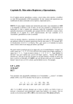
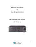
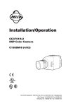
®
BB5A/BB5T Series
Back Box
Installation/
Operation Manual
C1488M-B (2/99)
Pelco • 3500 Pelco Way, Clovis • CA 93612-5699 USA • www.pelco.com
In North America and Canada: Tel (800) 289-9100 or FAX (800) 289-9150
International Customers: Tel (1-559) 292-1981 or FAX (1-559) 348-1120
CONTENTS
Section
Page
1.0 GENERAL .................................................................................................. 3
1.1 IMPORTANT SAFEGUARDS AND WARNINGS ............................... 3
1.2 REGULATORY NOTICES .................................................................. 4
1.3 UNPACKING INSTRUCTIONS .......................................................... 5
1.4 RECOMMENDED TOOLS ................................................................. 5
2.0 DESCRIPTION .......................................................................................... 6
2.1 MODELS ............................................................................................ 6
2.2 CERTIFICATIONS ............................................................................. 6
3.0 INSTALLATION FOR IN-CEILING MODELS ............................................. 7
3.1 CEILING AND BACK BOX PREPARATION ....................................... 7
3.1.1 Hard Ceiling ........................................................................... 7
3.1.2 Suspended Ceiling ................................................................. 8
3.2 WIRING ............................................................................................. 8
3.3 BACK BOX INSTALLATION .............................................................. 12
3.4 BACK BOX CONNECTIONS ............................................................ 13
4.0 INSTALLATION FOR PENDANT MODELS .............................................. 15
4.1 PENDANT-MOUNT INSTALLATION ................................................. 15
4.2 SURFACE-MOUNT INSTALLATION ................................................. 15
5.0 TROUBLESHOOTING .............................................................................. 16
5.1 SERVICE MANUAL .......................................................................... 16
6.0 SPECIFICATIONS .................................................................................... 17
7.0 WARRANTY AND RETURN INFORMATION ........................................... 20
LIST OF ILLUSTRATIONS
Figure
1
2
3
4
5
6
7
8
9
10
11
12
Page
Back Box Parts .................................................................................. 5
Compass Tool .................................................................................... 7
Conduit Fitting Installation ................................................................. 7
Installing Back Box ............................................................................. 9
Fastening Back Box ........................................................................... 9
Wiring Diagram for Spectra™ (Ver. 3.0) and Spectra II™ ................. 10
Wiring Diagram for Spectra™ Lite .................................................... 10
Interconnect Door ............................................................................. 12
Transformer Wiring ............................................................................ 13
Interconnect Circuit Board Electrical Connections for Spectra™
(Ver. 3.0) and Spectra II™ ................................................................. 13
Interconnect Circuit Board for Spectra™ Lite ................................... 14
SD5 Series Dimension Drawing ........................................................ 18
LIST OF TABLES
Table
A
B
Page
Video Coaxial Cable Wiring Distances .............................................. 8
24 VAC Wiring Distances .................................................................. 11
REVISION HISTORY
2
Manual #
C1488M
C1488M-A
Date
6/98
9/98
C1448M-B
2/99
Comments
Original version.
Rev A. Revised the manual to incorporate Spectra™
Lite material.
Rev B. Revised the input power ratings, certifications,
and operating temperatures. Revised model numbers for
Spectra Lite™.
Pelco Manual C1488M-B (2/99)
1.0 GENERAL
1.1 IMPORTANT SAFEGUARDS AND WARNINGS
Prior to installation and use of this product, the following WARNINGS should be
observed.
1.
Installation and servicing should only be done by qualified service personnel
and conform to all local codes.
2.
Unless the unit is specifically marked as a NEMA Type 3, 3R, 3S, 4, 4X, 6, or
6P enclosure, it is designed for indoor use only and it must not be installed
where exposed to rain and moisture.
3.
Only use replacement parts recommended by Pelco.
4.
After replacement/repair of this unit’s electrical components, conduct a resistance measurement between line and exposed parts to verify the exposed
parts have not been connected to line circuitry.
5.
The installation method and materials should be capable of supporting four
times the weight of the enclosure, pan/tilt, camera and lens combination.
The product and/or manual may bear the following marks:
This symbol indicates that dangerous voltage constituting a
risk of electric shock is present within this unit.
This symbol indicates that there are important operating and
maintenance instructions in the literature accompanying this
unit.
CAUTION:
RISK OF
ELECTRIC SHOCK.
DO NOT OPEN.
CAUTION:
TO REDUCE THE RISK OF ELECTRICAL SHOCK,
DO NOT REMOVE COVER. NO USERSERVICEABLE PARTS INSIDE. REFER SERVICING
TO QUALIFIED SERVICE PERSONNEL.
Please thoroughly familiarize yourself with the information
in this manual prior to installation and operation.
Pelco Manual C1488M-B (2/99)
3
1.2 REGULATORY NOTICES
NOTE: This equipment has been tested and found to comply with the limits of a
Class B digital device, pursuant to part 15 of the FCC rules. These limits are designed to provide reasonable protection against harmful interference in a residential installation. This equipment generates, uses, and can radiate radio frequency
energy and, if not installed and used in accordance with the instructions, may cause
harmful interference to radio communications. However there is no guarantee that
the interference will not occur in a particular installation. If this equipment does
cause harmful interference to radio or television reception, which can be determined by turning the equipment off and on, the user is encouraged to try and correct the interference by one or more of the following measures:
4
•
Reorient or relocate the receiving antenna.
•
Increase the separation between the equipment and the receiver.
•
Connect the equipment into an outlet on a circuit different from that to which
the receiver is connected.
•
Consult the dealer or an experienced radio/TV technician for help.
Pelco Manual C1488M-B (2/99)
1.3 UNPACKING INSTRUCTIONS
Unpack and inspect all parts carefully.
Be sure to save the shipping box and any inserts. They are the safest material in
which to make future shipments.
If an item appears to have been damaged in shipment, replace it properly in its box
and contact the factory at 1-800-289-9100 or 1-559-292-1981 for a replacement.
(International customers fax 1-559-348-1120 for authorization and instructions.)
If an item needs to be returned to the factory for repair, consult the WARRANTY
AND RETURN section of this manual for instructions.
The following items are supplied:
IN-CEILING MODELS
1
1
1
Back box
Installation/Operation Manual (C1488M)
Parts bag (refer to Figure 1)
1
Conduit fitting
1
Safety chain bracket
1
Lock nut
1
Compass tool
4
T-rail clip (clip, L-bracket, screw, lock washer, nut)
PENDANT MODELS
1
1
1
Back box
Tube of pipe sealant
Installation/Operation Manual (C1488M)
1.4 RECOMMENDED TOOLS
Pelco does not supply basic tools needed for the installation process. The following
tools are recommended:
Small flat screwdriver
Coaxial cable stripper
BNC crimp tool
Wire stripper
Wire cutter
Pen or pencil (in-ceiling models only)
Drill with 3/32-inch drill bit (in-ceiling models only)
Saw to cut hole in ceiling (in-ceiling models only)
Medium Phillips screwdriver (in-ceiling models and pendant surface-mount only)
Drill with hole saw (pendant surface-mount only)
COMPASS TOOL
SAFETY
BRACKET
CONDUIT FITTING
& LOCK NUT
T-RAIL CLIP
Figure 1. Back Box Parts
Pelco Manual C1488M-B (2/99)
5
2.0 DESCRIPTION
The BB5A Series back boxes are used with the SD5 Series of Spectra™ (Software
Version 3.0) domes and SD5A Series of Spectra II™ domes. The BB5T Series
back boxes are used with the SD5T Series of Spectra™ Lite domes.
The BB5A-F and BB5T-F are for indoor installation in hard ceilings or standard 2-foot
x 2-foot (61 x 61 cm) suspended ceilings.
The BB5A-PB (black), BB5A-PG (light gray), and BB5T-PG (light gray) pendant
back boxes are for indoor installation. For outdoor use, the BB5A-PG-E and BB5TPG-E include a heater and sun shield. The heater allows operation in temperatures
down to -60°F (-51°C).
2.1 MODELS
BB5A-F
Indoor back box for flush mounting in a ceiling
BB5A-PB
Black pendant-mount back box
BB5A-PG
Light gray pendant-mount back box
BB5A-PG-E
Same as BB5A-PG except includes heater and sun shield
BB5T-F
Indoor back box for flush mounting in a ceiling
BB5T-PG
Light gray pendant-mount back box
BB5T-PG-E
Same as BB5T-PG except includes heater and shield
2.2 CERTIFICATIONS
The products identified below have been tested and certified for agency compliance as noted.
Model
BB5A-F
BB5A-PB
BB5A-PG
BB5A-PG-E
BB5T-F
BB5T-PG
BB5T-PG-E
Agency Compliance Certification
CE
FCC
UL
CSA/cUL
X
X
X
X
X
X
X
X
X
X
X
X
X
X
Applicable CE, FCC, UL, and CSA/cUL directives/standards:
•
•
•
•
93/68/EEC–CE Mark Directive
89/336/EEC, 92/31/EEC–Electromagnetic Compatibility (EMC) Directives
EN 55022: 1984 Class A–Radio-frequency emissions limits
EN 50082-2: 1992–Immunity standard
IEC 801-2: 1984–ESD immunity
IEC 801-3: 1984–Radiated field immunity
IEC 801-4: 1988–Electrical Transients
FCC–47 CFR, Part 15, Subpart B, Class B
UL Listed (DRQH) E119552
cUL Listed (DRQH7)
Additional applicable standards:
•
•
6
NEMA Type 4 (except -F flush mount models; NEMA Type 1)
IP 66 (except -F flush mount models; NEMA Type 10)
Pelco Manual C1488M-B (2/99)
3.0 INSTALLATION FOR IN-CEILING MODELS
This manual covers the installation of the BB5A-F, BB5A-PB, BB5A-PG, BB5A-PG-E,
BB5T-F, BB5T-PG, and BB5T-PG-E back boxes only. For complete installation and
operating instructions for the SD5 Series of Spectra™ (Software Version 3.0) domes,
refer to manual C1456M-D; for the SD5A Series of Spectra II™ domes and SD5T
Series of Spectra™ Lite domes, refer to manual C1487M-B.
3.1 CEILING AND BACK BOX PREPARATION
3.1.1 Hard Ceiling
CAUTION: Be careful
not to cut outside of the
line. If you do, you may not
be able to install the back
box. Also, the trim ring
may not cover the hole.
1.
Locate the center point where you want to drill a hole in the ceiling.
2.
Drill a hole in the ceiling using a 3/32-inch drill bit.
3.
Remove the compass tool from the parts bag (refer to Figure 2). Press the
stud of the compass tool into the hole in the ceiling. Insert a pencil in the hole
in the other end of the compass and mark a circle on the ceiling.
4.
Carefully cut the circle out of the ceiling.
5.
Remove the conduit fitting, lock nut, and safety chain bracket from the parts
bag and attach them to the top or side of the back box as shown in Figure 3
(side installation shown).
Proceed to Section 3.2, WIRING.
ATTACH SAFETY CHAIN HERE
Figure 2. Compass Tool
Pelco Manual C1488M-B (2/99)
Figure 3. Conduit Fitting Installation
7
3.1.2 Suspended Ceiling
CAUTION: The ceiling
tile must be capable of
supporting 16 pounds
(7.3 kg) of weight. If the
ceiling tile will not support
this weight, use the optional SD5-P metal panel.
CAUTION: Be careful
not to cut outside of the
line. If you do, you may not
be able to install the back
box. Also, the trim ring
may not cover the hole.
1.
Remove the ceiling tile from the ceiling.
2.
Locate the center point to drill a hole in the tile.
3.
Drill a hole in the ceiling tile using a 3/32-inch drill bit.
4.
Remove the compass tool from the parts bag (refer to Figure 2). Press the
stud of the compass tool into the hole in the ceiling. Insert a pencil in the hole
in the other end of the compass and mark a circle on the ceiling.
5.
Carefully cut the circle out of the ceiling tile.
6.
Remove the conduit fitting, lock nut, and safety chain bracket from the parts
bag and attach them to the top or side of the back box as shown in Figure 3
(side installation shown).
7.
Refer to Figure 4. Compress the spring clips on the back box with your hands
and push the back box through the hole in the ceiling tile. The spring clips will
spring out when they clear the ceiling tile.
8.
Refer to Figure 5. Tighten the screws until the spring clips hold the back box
firmly to the ceiling tile. You will hear a clicking noise when the screws are tight.
Do not install the ceiling tile in the ceiling yet.
Proceed to Section 3.2, WIRING.
3.2 WIRING
Bring wiring to the back box opening in the ceiling. Do not attach the wiring to the
back box. You will do that later.
Refer to Figure 6 for the wiring diagram for Spectra™ (Version 3.0) and Spectra II™,
and to Figure 7 for the Spectra™ Lite.
Wiring is required for power, earth ground, and video.
Refer to Table A for the type of video coaxial cable to use.
NOTE: The dome will stop oper-
ating if the voltage at the dome
drops below 18 VAC. It will turn
back on when the voltage exceeds
18 VAC.
Table A. Video Coaxial Cable
Wiring Distances
Cable Type* Maximum Distance
RG59/U
RG6/U
RG11/U
Input power is 24 VAC only. Power consumption is 30 vA per dome for indoor models
and 75 vA for outdoor models. Refer to Table B to determine the size of wire to use.
Use a 24 VAC transformer with the following minimum vA:
40 vA per dome
For indoor models (without heater)
100 vA per dome
For outdoor models (with heater)
Refer to Figure 9 for wiring multiple domes from the same transformer.
If you will use a Coaxitron® controller, the control signals to operate the dome drive
will be transmitted over the video coax. The RS-422 control lines are not used.
750 ft (229 m)
1,000 ft (305 m)
1,500 ft (457 m)
If you will not use a Coaxitron® controller, use the RS-422 control lines. Use 22gauge wire. The distance will be the same as the video coax.
* Minimum cable requirements:
75 ohms impedance
All-copper center conductor
All-copper braided shield with
95% braid coverage
Optional wiring may be provided for alarm inputs (maximum of seven), relay output,
and auxiliary output.
8
Proceed to Section 3.3, BACK BOX INSTALLATION.
Pelco Manual C1488M-B (2/99)
HARD CEILING
OR
CEILING TILE
Figure 4. Installing Back Box
HARD CEILING
OR
CEILING TILE
T-RAIL CLIP
FOR
CEILING TILE
T-RAIL CLIP
FOR
CEILING TILE
Figure 5. Fastening Back Box
Pelco Manual C1488M-B (2/99)
9
CONTROL
(RS-422)
7
+5 to +24 VDC
EXTERNAL RELAY
(WIRING EXAMPLE)
Figure 6. Wiring Diagram for Spectra™ (Ver. 3.0) and Spectra II™
THUMBSCREW
Figure 7. Wiring Diagram for Spectra™ Lite
10
Pelco Manual C1488M-B (2/99)
Table B. 24 VAC Wiring Distances
The following are the recommended maximum distances for 24 VAC with a 10percent voltage drop. (Ten percent is generally the maximum allowable voltage drop
for AC-powered devices.)
Wire Gauge
Pelco Manual C1488M-B (2/99)
20
18
16
14
12
10
30 vA
94 ft
(28 m)
150 ft
(45 m)
238 ft
(72 m)
380 ft
(115 m)
603 ft
(183 m)
960 ft
(292 m)
75 vA
37 ft
(11 m)
60 ft
(18 m)
95 ft
(29 m)
152 ft
(46 m)
241 ft
(73 m)
384 ft
(117 m)
11
3.3 BACK BOX INSTALLATION
OPTIONAL PROCEDURE: If
you prefer, you may make the wiring connections inside the back box
before installing the back box in the
ceiling.
To do this, loosen the thumbscrew
inside the back box and open the
hinged door (refer to Figure 8).
Bring the wiring into the back box
through the conduit fitting. Follow
the steps in Section 3.4, “Back Box
Connections,” and then return to
this section.
CAUTION: The ceiling
must be capable of supporting 16 pounds (7.3
kg) of weight. If the ceiling will not support this
weight, provide additional
reinforcement. Also, a
suitable safety chain must
be attached to the back
box to support up to 16
pounds (7.3 kg) in the
event of a ceiling failure.
1.
Suspended Ceiling Only (for hard ceiling, go to step 2) – Install the ceiling
tile with the back box. Attach a T-rail clip on each side of the ceiling tile as
shown in Figure 5.
2.
Install a safety chain or cable (not supplied) that will support up to 16 pounds
(7.3 kg). Fasten one end to a support structure in the ceiling. Fasten the other
end to the safety chain bracket (refer to Figure 3) to prevent the back box from
falling.
3.
Refer to Figure 8. Loosen the thumbscrew inside the back box and open the
hinged door.
4.
Bring the wiring into the back box through the conduit fitting. If the wiring is
inside flexible conduit, connect the conduit to the fitting on the back box.
5.
Hard Ceiling Only - Refer to Figure 4. Compress the spring clips on the back
box with your hands and push the back box through the hole in the ceiling. The
spring clips will spring out when they clear the ceiling. Refer to Figure 5. Tighten
the screws until the spring clips hold the back box firmly to the ceiling. You will
hear a clicking noise when the screws are tight.
Proceed to Section 3.4, BACK BOX CONNECTIONS.
THUMBSCREW
Figure 8. Interconnect Door
12
Pelco Manual C1488M-B (2/99)
3.4 BACK BOX CONNECTIONS
Depending on the type of dome, refer to either Figure 10 or 11 to attach the wiring to the
interconnect circuit board inside the back box. Also refer to Figure 6 or 7 if necessary.
WARNING: Make sure
you wire power to the
outer connectors of the
terminal block and ground
to the middle connector.
Otherwise, you could
damage the dome.
1.
Earth Ground - Connect earth ground to the middle connector on the power
connector.
2.
Power - Connect 24 VAC from the transformer to the outer terminals on the
power connector. It does not matter which lead goes to which terminal.
If you are wiring more than one dome from the same transformer, it is important to wire the power connector in each dome the same way. That is, the
wiring from one side of the transformer must be connected to the same connector on each dome. If you reverse the wiring, the cameras will be out of
phase with each other and may produce what appears to be vertical roll when
switching between cameras. Refer to Figure 9 for a wiring diagram.
3.
Video - Connect the coaxial cable to the BNC video connector.
DOME 1
POWER
DOME 2
POWER
EXAMPLE: If each dome
requires 20 vA, three domes
require a 60 vA transformer.
DOME 3
POWER
Figure 9. Transformer Wiring
HTR/FAN
RS-422
CONTROL
SIGNALS
1
2
RX–
ALARMS
3
4
5
NC
AUX 2
GND
TX–
RELAY
GND
NO
COM
DOME DRIVE
CONNECTOR
RX+
TX+
6
7
AUX 1
VIDEO
PWR IN
FUSE
POWER
(24 VAC ONLY)
CONNECTOR
FOR OPTIONAL
TRANSLATOR
SUBASSEMBLY
FAN
24 VAC
MIDDLE
PIN IS
GND
1.6 A
Figure 10. Interconnect Circuit Board Electrical Connections for
Spectra™ (Ver. 3.0) and Spectra II™
Pelco Manual C1488M-B (2/99)
13
HTR/FAN
VIDEO
RS-422
CONTROL
SIGNALS
RX–
CONNECTOR
FOR OPTIONAL
TRANSLATOR
SUBASSEMBLY
DOME DRIVE
CONNECTOR
RX+
TX–
TX+
PWR IN
FUSE
POWER
(24 VAC ONLY)
FAN
24 VAC
MIDDLE
PIN IS
GND
1.6 A
Figure 11. Interconnect Circuit Board for Spectra™ Lite
4.
Control - If you are using a Coaxitron® controller, control signals will be transmitted over the video coax.
If you are using RS-422 (P or D) control signals, connect the control lines from
the controller to the circuit board. Connect the wires as follows:
From controller
RXRX+
TXTX+
NOTE: Connect only a low volt-
5.
Heater/Fan - The heater/fan is not used on indoor models.
6.
Alarm Inputs - (Spectra™ [Version 3.0] and Spectra II™ Only) If you need
alarm inputs, connect them. The maximum number of alarm inputs is seven.
Refer to Figure 6 for a typical wiring example. Alarm inputs require a ground
signal through a contact closure, such as a switch.
7.
AUX 1 - (Spectra™ [Version 3.0] and Spectra II™ Only) An AUX 1 command from the controller will activate the relay output. If you need the relay, wire
it as required. Refer to Figure 6. The relay contacts are shown when AUX 1 is
inactive. When an AUX 1 command is issued, the relay contacts will reverse and
remain latched until a clear command is issued.
8.
AUX 2 - (Spectra™ [Version 3.0] and Spectra II™ Only) An AUX 2 command
from the controller will place a ground at the output of AUX 2 to operate the
device connected to it. The output will remain latched until a clear command is
issued. If you need the AUX 2 output, wire it as required. Refer to Figure 6 for
typical wiring examples. The AUX 2 output is an open collector transistor driver
which is capable of passing a maximum of 150 mA at 32 VDC. It is capable of
driving TTL logic circuits or low-current reed relays. If you use an external relay,
make sure that both the supply voltage and the current requirements are well
below the maximum of 32 VDC and 150 mA. Exceeding these values will cause
permanent damage to the dome. If you are not familiar with open collector drive
requirements, contact Pelco technical support for assistance.
9.
Close the door and tighten the thumbscrew securely.
age device to the relay output.
Maximum current rating of the relay contacts is two amperes.
CAUTION: The maxi-
mum output of AUX 2 is
150 mA. If you connect a
device that draws more
current, you could destroy
the output transistor. The
output is intended to drive
logic circuits or low-current
devices. If higher current
is required, connect the
output to a relay.
CAUTION: Leave adequate slack in the wiring
to permit the door to open
without pulling on the connectors.
To 4-Wire terminal on circuit board
TXTX+
RXRX+
10. Turn on power to the back box. The red LED on the interconnect door should
light. The fan will not operate until a dome drive is installed.
If the LED does not light, correct the trouble before proceeding. Refer to Section 5.0, TROUBLESHOOTING.
14
Pelco Manual C1488M-B (2/99)
4.0 INSTALLATION FOR PENDANT MODELS
4.1 PENDANT-MOUNT INSTALLATION
1.
Install the pendant dome mount. Refer to the instructions provided with the
mount. If the mount is outdoors, make sure it is properly sealed to keep moisture out.
2.
Bring the wiring for the dome through the mount. Refer to Section 3.2, WIRING.
3.
Refer to Figure 8. Loosen the thumbscrew inside the back box and open the
hinged door.
4.
Screw the back box into the mount as far as possible and bring the wiring into
the back box. If outdoors, apply the provided pipe sealant to the threads on the
back box.
5.
Attach the wiring to the back box. Refer to Section 3.4, BACK BOX CONNECTIONS. Hanging down from the back box is a short cable (the trim ring leash)
and a heater connector with two wires (outdoor units only). The leash and
heater wiring will be connected when the lower dome is installed.
NOTE: If outdoors, apply Duct
Seal inside the pipe portion of the
back box to prevent moisture or
cold air inside the mount from entering the unit and causing condensation on the dome. Duct Seal can
be purchased through local electrical supply houses.
4.2 SURFACE-MOUNT INSTALLATION
Pelco Manual C1488M-B (2/99)
1.
Use a hole saw to drill a hole in the ceiling where you want to hang the pendant dome.
2.
Bring the wiring for the dome to the opening. Refer to Section 3.2, WIRING.
3.
Refer to Figure 8. Loosen the thumbscrew inside the back box and open the
hinged door.
4.
Remove the gasket and the top mount from the back box by taking out the
three screws and lock washers.
5.
Attach the back box to the ceiling using #8 hardware (not supplied).
6.
Attach the wiring to the back box. Refer to Section 3.4, BACK BOX CONNECTIONS. Hanging down from the back box is a short cable (the trim ring leash)
and a heater connector with two wires (outdoor units only). The leash and
heater wiring will be connected when the lower dome is installed.
15
5.0 TROUBLESHOOTING
Symptom: LED does not light.
If the red power LED on the door of the interconnect circuit board in the back box
does not light:
1.
Turn off power.
2.
Open the door to the interconnect circuit board and check the fuse. Refer to
Figure 10 for the location of the fuse. If the fuse is bad, replace it. To order a
replacement fuse from Pelco, specify the part number FUS1.6-5X20FAST. This
is a 1.6-ampere fuse, 5 x 20 mm, fast blow.
3.
If the fuse is good, turn on power and use a voltmeter to check if 24 VAC is
getting to the power connector on the interconnect circuit board. Refer to Figure 10 for the location of the AC power connector.
4.
If there is 24 VAC to the power connector, turn off the power and return the
back box electronic assembly to the factory for repair.
To remove the back box electronic assembly:
a.
Turn off power.
b.
Open the interconnect door and disconnect all wiring to the back box.
c.
Use an 11/32-inch socket driver to remove the three 8-32 washers and
nuts that hold the electronic assembly to the back box. When the screws
are removed, the interconnect back box receptacle will drop down. It may
be necessary to move the open interconnect door past 90° vertical toward the side of the back box to release the door from built-in grounding
strip (and free the interconnect back box receptacle).
d.
Remove the interconnect back box receptacle with the electronic components from the back box.
5.1 SERVICE MANUAL
If you need to service your unit, obtain a service manual in on of the following ways:
•
•
16
Go to Pelco’s web site at ftp://www.pelco.com and find service manual
C1455SM.
Contact Pelco’s Literature Department and request service manual C1455SM.
Pelco Manual C1488M-B (2/99)
6.0 SPECIFICATIONS
MECHANICAL
Construction
Back box:
Aluminum
Cable Entry
In-Ceiling:
Pendant:
.75" (1.91 cm) conduit fitting
Through 1.5" (3.81 cm) NPT pendant mount
Dimensions:
See Figure 12
ELECTRICAL
Input Voltage:
18-30 VAC, 24 VAC nominal
Input Power
In-ceiling:
30 vA
Indoor pendant: 30 vA
Outdoor pendant: 75 vA
Fuse:
1.6 A
Relay
Contacts (AUX 1)*
Type:
Form C
Voltage:
Low voltage (< 40 v)
Current:
2 A maximum
AUX 2 Output*
Type:
Voltage:
Current:
Open collector transistor output
32 VDC maximum
150 mA maximum
* Applies to Spectra™ (Version 3.0) and Spectra II™ only.
GENERAL
Environment
In-Ceiling:
Pendant:
Operating Range
In-Ceiling:
Indoor only
Indoor/outdoor
32° to 140°F (0° to 60°C) absolute operating temperatures;
32° to 122°F (0° to 50°C) sustained operating temperatures
Pendant
Without Heater: 32° to 140°F (0° to 60°C) absolute operating temperatures;
32° to 122°F (0° to 50°C) sustained operating temperatures
With Heater*:
Pelco Manual C1488M-B (2/99)
Maximum operating temperature:
140°F (60°C) absolute; 122°F (50°C) sustained
Minimum operating temperature:
-60°F (-51.11°C) absolute; minimal icing at -50°F (-45.56°C)
sustained; prevents icing at -40°F (-40°C) sustained; de-ices
.1" (2.5 mm) within 3 hours after power-up
17
Weight
In-Ceiling
Back Box
Pendant
Back Box†
Unit
Shipping
2.6 lbs (1.18 kg)
4.0 lbs (1.81 kg)
2.85 lbs (1.28 kg)
5.0 lbs (2.27 kg)
* Assumes no wind chill factor; for detailed test conditions, contact Pelco.
†
Add 1.25 lbs (.57 kg) for outdoor models with sun shield and heater
(Design and product specifications subject to change without notice.)
TOP PORTION OF BACK BOX
IS REMOVABLE FOR SURFACE
MOUNT APPLICATIONS
DOME IS SECURED
TO CEILING BY
MOUNTING BRACKET
7.25 (18.13)
8.52
(21.64)
6.60 (16.76)
5.25
(13.34)
6.75
(17.15)
10.90
27.69
5.83
(14.80)
3.25
(8.26)
5.90 (14.99)
5.90
(14.99)
8.25 (20.96)
In-Ceiling Dome
Pendant Dome
NOTE: VALUES IN PARENTHESES ARE CENTIMETERS, ALL OTHERS ARE INCHES.
Figure 12. SD5 Series Dimension Drawing
18
Pelco Manual C1488M-B (2/99)
NOTES
Pelco Manual C1488M-B (2/99)
19
7.0 WARRANTY AND RETURN INFORMATION
WARRANTY
Pelco will repair or replace, without charge, any merchandise proved defective in material or
workmanship for a period of one year after the date of shipment.
Exceptions to this warranty are as noted below:
• Five years on FT/FR8000 Series fiber optic products.
• Three years on Genex® Series products (multiplexers, server, and keyboard).
• Three years on Camclosure® and fixed camera models, except the CC3701H-2, CC3701H-2X,
CC3751H-2, CC3651H-2X, MC3651H-2, and MC3651H-2X camera models, which have a fiveyear warranty.
• Two years on standard motorized or fixed focal length lenses.
• Two years on Legacy®, CM6700/CM6800/CM9700 Series matrix, and DF5/DF8 Series fixed
dome products.
• Two years on Spectra®, Esprit®, ExSite™, and PS20 scanners, including when used in
continuous motion applications.
• Two years on Esprit® and WW5700 Series window wiper (excluding wiper blades).
• Eighteen months on DX Series digital video recorders, NVR300 Series network video
recorders, and Endura ™ Series distributed network-based video products.
• One year (except video heads) on video cassette recorders (VCRs). Video heads will be
covered for a period of six months.
• Six months on all pan and tilts, scanners or preset lenses used in continuous motion applications
(that is, preset scan, tour and auto scan modes).
Pelco will warrant all replacement parts and repairs for 90 days from the date of Pelco shipment.
All goods requiring warranty repair shall be sent freight prepaid to Pelco, Clovis, California. Repairs
made necessary by reason of misuse, alteration, normal wear, or accident are not covered under
this warranty.
Pelco assumes no risk and shall be subject to no liability for damages or loss resulting from the
specific use or application made of the Products. Pelco’s liability for any claim, whether based on
breach of contract, negligence, infringement of any rights of any party or product liability, relating
to the Products shall not exceed the price paid by the Dealer to Pelco for such Products. In no event
will Pelco be liable for any special, incidental or consequential damages (including loss of use, loss
of profit and claims of third parties) however caused, whether by the negligence of Pelco or
otherwise.
The above warranty provides the Dealer with specific legal rights. The Dealer may also have
additional rights, which are subject to variation from state to state.
If a warranty repair is required, the Dealer must contact Pelco at (800) 289-9100 or (559) 292-1981
to obtain a Repair Authorization number (RA), and provide the following information:
1. Model and serial number
2. Date of shipment, P.O. number, Sales Order number, or Pelco invoice number
3. Details of the defect or problem
If there is a dispute regarding the warranty of a product which does not fall under the warranty
conditions stated above, please include a written explanation with the product when returned.
Method of return shipment shall be the same or equal to the method by which the item was received
by Pelco.
RETURNS
Pelco, the Pelco logo, Camclosure, Esprit,
Genex, Legacy, and Spectra are registered
trademarks of Pelco.
Endura and ExSite are trademarks of Pelco.
© Copyright 1999, Pelco. All rights reserved.
20
In order to expedite parts returned to the factory for repair or credit, please call the factory at (800)
289-9100 or (559) 292-1981 to obtain an authorization number (CA number if returned for credit,
and RA number if returned for repair).
All merchandise returned for credit may be subject to a 20% restocking and refurbishing charge.
Goods returned for repair or credit should be clearly identified with the assigned CA or RA number
and freight should be prepaid. Ship to the appropriate address below.
If you are located within the continental U.S., Alaska, Hawaii or Puerto Rico, send goods to:
Service Department
Pelco
3500 Pelco Way
Clovis, CA 93612-5699
If you are located outside the continental U.S., Alaska, Hawaii or Puerto Rico and are instructed
to return goods to the USA, you may do one of the following:
If the goods are to be sent by a COURIER SERVICE, send the goods to:
Pelco
3500 Pelco Way
Clovis, CA 93612-5699 USA
If the goods are to be sent by a FREIGHT FORWARDER, send the goods to:
Pelco c/o Expeditors
473 Eccles Avenue
South San Francisco, CA 94080 USA
Phone: 650-737-1700
Fax: 650-737-0933
Pelco Manual C1488M-B (2/99)