1
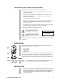
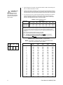
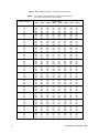
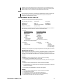
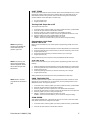
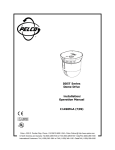
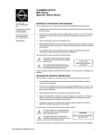
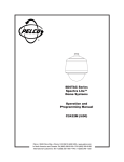
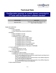
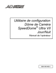
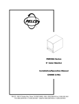
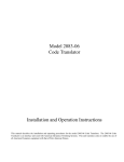
®
DD5TA Series
Dome Drive
Installation/
Operation Manual
C1498M-B (7/99)
UL
®
LISTED
Pelco • 300 W. Pontiac Way, Clovis • CA 93612-5699 USA • Pelco Online @ http://www.pelco.com
In North America and Canada: Tel (800) 289-9100 or FAX (800) 289-9150 • DataFAX (800) 289-9108
International Customers: Tel (1-559) 292-1981 or FAX (1-559) 348-1120 • DataFAX (1-559) 292-0435
CONTENTS
Section
Page
IMPORTANT SAFEGUARDS AND WARNINGS ................................................................ 3
DESCRIPTION ................................................................................................................... 3
MODELS .................................................................................................................... 3
INSTALLATION ................................................................................................................... 3
OPERATION ...................................................................................................................... 9
POWER-UP DISPLAY ................................................................................................ 9
PAN AND TILT FUNCTIONS ..................................................................................... 10
AUTO FLIP ........................................................................................................ 10
SCAN SPEED ................................................................................................... 10
ZOOM ....................................................................................................................... 10
PRESET FUNCTIONS .............................................................................................. 10
RANDOM, FRAME, AND AUTO SCANNING ........................................................... 10
PARK ......................................................................................................................... 11
PROGRAMMING THE SPECTRA LITE™ ................................................................ 11
MAIN MENU ACCESS ...................................................................................... 11
BACKLIGHT COMPENSATION ........................................................................ 12
RESET CAMERA .............................................................................................. 12
GAIN/AGC ......................................................................................................... 13
AUTO IRIS ........................................................................................................ 13
SHUTTER SPEED ............................................................................................ 14
AUTO-FOCUS MODE ....................................................................................... 14
SHARPNESS .................................................................................................... 15
WHITE BALANCE ............................................................................................. 15
LINE SYNCHRONIZATION ............................................................................... 15
POWER-UP MODE ........................................................................................... 16
AUTO FLIP ........................................................................................................ 16
LIMIT STOPS .................................................................................................... 17
PARK TIME MINUTES ...................................................................................... 17
SCAN SPEED ................................................................................................... 17
TROUBLESHOOTING ...................................................................................................... 18
BACK BOX ELECTRONIC ASSEMBLY REMOVAL .................................................. 19
SPECIFICATIONS ............................................................................................................. 19
REGULATORY NOTICES ......................................................................................... 20
WARRANTY AND RETURN INFORMATION ................................................................... 20
LIST OF ILLUSTRATIONS
Figure
1
2
Page
System Components (In-Ceiling Model Shown) ................................................ 3
Backlight ............................................................................................................ 12
LIST OF TABLES
Table
A
B
C
2
Page
Switch Settings for SW1 ..................................................................................... 4
Switch Settings for SW2 – P-Type Control ......................................................... 4
Switch Settings for SW2 – D-Type Control ......................................................... 5
Pelco Manual C1498M-B (7/99)
IMPORTANT SAFEGUARDS AND WARNINGS
Observe the following warnings before installing and using this product.
1.
Installation and servicing should only be done by qualified service personnel and
conform to all local codes.
2.
Unless the unit is specifically marked as a NEMA Type 3, 3R, 3S, 4, 4X, 6, or 6P
enclosure, it is designed for indoor use only and it must not be installed where
exposed to rain and moisture.
3.
Only use replacement parts Pelco recommends.
4.
After replacing or repairing this unit’s electrical components, measure the resistance
between the line and exposed parts to verify the exposed parts have not been
connected to line circuitry.
5.
The installation method and materials should be capable of supporting four times the
weight of the enclosure, pan and tilt, camera and lens combination.
The product and/or manual may bear the following marks:
This symbol indicates that dangerous
voltage constituting a risk of electric
shock is present within this unit.
This symbol indicates that there are
important operating and maintenance
instructions in the literature accompanying this unit.
CAUTION:
RISK OF ELECTRIC SHOCK.
DO NOT OPEN.
Please thoroughly familiarize yourself with the information in this manual prior to installation
and operation.
DESCRIPTION
Dome drives in the DD5TA Series are part of the Spectra Lite™ dome system (refer to
Figure 1). The dome drives can do the following:
BACK
BOX
•
•
•
•
DOME
DRIVE
LOWER
DOME
360° pan rotation
preset positioning
+2 to -92° tilt
variable speed
All dome drives include a color CCD camera with a 16X zoom lens and capability to focus
when going to a preset position. An integral receiver has a switch to select the type of
control. The receiver supports Coaxitron® and RS-422 control types. The dome operates on
24 VAC. The dome drive is quickly installed and removed from the back box without tools.
MODELS
Figure 1. System Components (In-Ceiling
Model Shown)
DD5TAC
DD5TAC-X
Dome drive with color camera and lens, NTSC standard (FCC, UL, cUL)
Dome drive with color camera and lens, PAL standard (CE)
INSTALLATION
1.
Pelco Manual C1498M-B (7/99)
Turn on power to the back box. The red LED should light to indicate power. If the LED
does not light, correct the trouble before proceeding. (Refer to the Troubleshooting
section of the SD5 Series Spectra II™ and Spectra Lite™ Dome Installation/Operation
manual.) If the light operates, you may either leave power on or turn it off before
continuing the installation.
3
CAUTION: Make
sure the dome
drive locks into
place. Pull down on the
dome drive with moderate
pressure to ensure that it
stays in place.
2.
Set the switches on the bottom of the dome drive. Refer to Table A for the settings for
SW1, and Table B and Table C for SW2.
3.
Install the dome drive in the back box. Line up the green tab and red tab on the dome
drive with the green label and red label on the back box. Raise the dome drive into the
back box and push on the ends of the tabs until they both click into place on the back box.
4.
Turn on power, if it is not on. Listen for the fan operating. If the fan does not work, the
dome will overheat and shut down. If the fan does not work, return the back box
electronic assembly and dome drive to the factory for repair. Refer to the Back Box
Electronic Assembly Removal section in manual C1487M-C.
Table A. Switch Settings for SW1
Control Type
Coaxitron®
P-Type Control
D-Type Control
SW1-1
SW1-2
SW1-3
Switch Setting
SW1-4 SW1-5
SW1-6
SW1-7
SW1-8
OFF
ON
OFF
OFF
OFF
ON
OFF
OFF
OFF
OFF
OFF
OFF
OFF
OFF
OFF
OFF
OFF
OFF*
OFF**
OFF**
OFF**
OFF
OFF
OFF
NOTES: Switches SW1-3 through SW1-6 MUST be OFF.
D-type control is RS-422 that is compatible with Pelco‘s CM6700, MPT9500 and CM8500
controllers or with American Dynamics control systems using the AD2083 Translator.
P-type control is RS-422 that is compatible with Pelco's CM6700/CM9750/CM9760 control
systems.
* OFF - Use with controllers that have more than 32 presets.
ON - Use with American Dynamics controllers (32 presets).
** OFF - Use with all control systems except CM9502 with variable speed keyboards.
For CM9502 with fixed speed keyboards, set switch OFF.
ON - Use with CM9502 with variable speed keyboards for smoother joystick control.
Table B. Switch Settings for SW2 – P-Type Control
NOTE: For Coaxitron® controls, SW2 is not used; set all switches OFF.
For D-type control systems, refer to Table C.
Baud
Switch Setting
Rate SW2-6 SW2-7 SW2-8
2400
4800
9600
4
OFF
ON
OFF
OFF
OFF
ON
OFF
OFF
OFF
Receiver Address
1
2
3
4
5
6
7
8
9
10
11
12
13
14
15
16
17
18
19
20
21
22
23
24
25
26
27
28
29
30
31
32
SW2-1
SW2-2
Switch Setting
SW2-3
SW2-4
SW2-5
OFF
ON
OFF
ON
OFF
ON
OFF
ON
OFF
ON
OFF
ON
OFF
ON
OFF
ON
OFF
ON
OFF
ON
OFF
ON
OFF
ON
OFF
ON
OFF
ON
OFF
ON
OFF
ON
OFF
OFF
ON
ON
OFF
OFF
ON
ON
OFF
OFF
ON
ON
OFF
OFF
ON
ON
OFF
OFF
ON
ON
OFF
OFF
ON
ON
OFF
OFF
ON
ON
OFF
OFF
ON
ON
OFF
OFF
OFF
OFF
ON
ON
ON
ON
OFF
OFF
OFF
OFF
ON
ON
ON
ON
OFF
OFF
OFF
OFF
ON
ON
ON
ON
OFF
OFF
OFF
OFF
ON
ON
ON
ON
OFF
OFF
OFF
OFF
OFF
OFF
OFF
OFF
ON
ON
ON
ON
ON
ON
ON
ON
OFF
OFF
OFF
OFF
OFF
OFF
OFF
OFF
ON
ON
ON
ON
ON
ON
ON
ON
OFF
OFF
OFF
OFF
OFF
OFF
OFF
OFF
OFF
OFF
OFF
OFF
OFF
OFF
OFF
OFF
ON
ON
ON
ON
ON
ON
ON
ON
ON
ON
ON
ON
ON
ON
ON
ON
Pelco Manual C1498M-B (7/99)
Table C. Switch Settings for SW2 – D-Type Control
NOTE:
For Coaxitron® controls, SW2 is not used; set all switches OFF.
For P-type control systems, refer to Table B.
Receiver Address
1
2
3
4
5
6
7
8
9
10
11
12
13
14
15
16
17
18
19
20
21
22
23
24
25
26
27
28
29
30
31
32
33
34
35
36
37
38
39
40
41
42
43
44
45
46
47
48
49
50
51
52
53
54
55
56
SW2-1
SW2-2
Switch Setting
SW2-3 SW2-4
SW2-5
SW2-6
SW2-7
SW2-8
ON
OFF
ON
OFF
ON
OFF
ON
OFF
ON
OFF
ON
OFF
ON
OFF
ON
OFF
ON
OFF
ON
OFF
ON
OFF
ON
OFF
ON
OFF
ON
OFF
ON
OFF
ON
OFF
ON
OFF
ON
OFF
ON
OFF
ON
OFF
ON
OFF
ON
OFF
ON
OFF
ON
OFF
ON
OFF
ON
OFF
ON
OFF
ON
OFF
OFF
ON
ON
OFF
OFF
ON
ON
OFF
OFF
ON
ON
OFF
OFF
ON
ON
OFF
OFF
ON
ON
OFF
OFF
ON
ON
OFF
OFF
ON
ON
OFF
OFF
ON
ON
OFF
OFF
ON
ON
OFF
OFF
ON
ON
OFF
OFF
ON
ON
OFF
OFF
ON
ON
OFF
OFF
ON
ON
OFF
OFF
ON
ON
OFF
OFF
OFF
OFF
ON
ON
ON
ON
OFF
OFF
OFF
OFF
ON
ON
ON
ON
OFF
OFF
OFF
OFF
ON
ON
ON
ON
OFF
OFF
OFF
OFF
ON
ON
ON
ON
OFF
OFF
OFF
OFF
ON
ON
ON
ON
OFF
OFF
OFF
OFF
ON
ON
ON
ON
OFF
OFF
OFF
OFF
ON
ON
ON
ON
OFF
OFF
OFF
OFF
OFF
OFF
OFF
OFF
OFF
OFF
OFF
OFF
OFF
OFF
OFF
OFF
ON
ON
ON
ON
ON
ON
ON
ON
ON
ON
ON
ON
ON
ON
ON
ON
OFF
OFF
OFF
OFF
OFF
OFF
OFF
OFF
OFF
OFF
OFF
OFF
OFF
OFF
OFF
OFF
ON
ON
ON
ON
ON
ON
ON
ON
ON
OFF
OFF
OFF
OFF
OFF
OFF
OFF
OFF
OFF
OFF
OFF
OFF
OFF
OFF
OFF
OFF
OFF
OFF
OFF
OFF
OFF
OFF
OFF
OFF
OFF
OFF
OFF
OFF
OFF
OFF
OFF
ON
ON
ON
ON
ON
ON
ON
ON
ON
ON
ON
ON
ON
ON
ON
ON
ON
ON
ON
ON
ON
ON
ON
ON
ON
OFF
OFF
OFF
OFF
OFF
OFF
OFF
OFF
OFF
OFF
OFF
OFF
OFF
OFF
OFF
OFF
OFF
OFF
OFF
OFF
OFF
OFF
OFF
OFF
OFF
OFF
OFF
OFF
OFF
OFF
OFF
OFF
OFF
OFF
OFF
OFF
OFF
OFF
OFF
OFF
OFF
OFF
OFF
OFF
OFF
OFF
OFF
OFF
OFF
OFF
OFF
OFF
OFF
OFF
OFF
OFF
OFF
OFF
OFF
OFF
OFF
OFF
OFF
OFF
OFF
OFF
OFF
OFF
OFF
OFF
OFF
OFF
OFF
OFF
OFF
OFF
OFF
OFF
OFF
OFF
OFF
OFF
OFF
OFF
OFF
OFF
OFF
OFF
OFF
OFF
OFF
OFF
OFF
OFF
OFF
OFF
OFF
OFF
OFF
OFF
OFF
OFF
OFF
OFF
OFF
OFF
OFF
OFF
OFF
OFF
OFF
OFF
OFF
OFF
OFF
OFF
OFF
OFF
OFF
ON
ON
ON
ON
ON
ON
ON
ON
OFF
OFF
OFF
OFF
OFF
OFF
OFF
OFF
ON
ON
ON
ON
ON
ON
ON
ON
OFF
OFF
OFF
OFF
OFF
OFF
OFF
OFF
ON
ON
ON
ON
ON
ON
ON
ON
OFF
OFF
OFF
OFF
OFF
OFF
OFF
OFF
ON
(Continued on next page)
Pelco Manual C1498M-B (7/99)
5
Table C. Switch Settings for SW2 – D-Type Control (Continued)
NOTE:
For Coaxitron® controls, SW2 is not used; set all switches OFF.
For P-type control systems, refer to Table B.
Receiver Address
SW2-1
57
58
59
60
61
62
63
64
65
66
67
68
69
70
71
72
73
74
75
76
77
78
79
80
81
82
83
84
85
86
87
88
89
90
91
92
93
94
95
96
97
98
99
100
101
102
103
104
105
106
107
108
109
110
111
112
ON
OFF
ON
OFF
ON
OFF
ON
OFF
ON
OFF
ON
OFF
ON
OFF
ON
OFF
ON
OFF
ON
OFF
ON
OFF
ON
OFF
ON
OFF
ON
OFF
ON
OFF
ON
OFF
ON
OFF
ON
OFF
ON
OFF
ON
OFF
ON
OFF
ON
OFF
ON
OFF
ON
OFF
ON
OFF
ON
OFF
ON
OFF
ON
OFF
SW2-2
OFF
ON
ON
OFF
OFF
ON
ON
OFF
OFF
ON
ON
OFF
OFF
ON
ON
OFF
OFF
ON
ON
OFF
OFF
ON
ON
OFF
OFF
ON
ON
OFF
OFF
ON
ON
OFF
OFF
ON
ON
OFF
OFF
ON
ON
OFF
OFF
ON
ON
OFF
OFF
ON
ON
OFF
OFF
ON
ON
OFF
OFF
ON
ON
OFF
SW2-3
OFF
OFF
OFF
ON
ON
ON
ON
OFF
OFF
OFF
OFF
ON
ON
ON
ON
OFF
OFF
OFF
OFF
ON
ON
ON
ON
OFF
OFF
OFF
OFF
ON
ON
ON
ON
OFF
OFF
OFF
OFF
ON
ON
ON
ON
OFF
OFF
OFF
OFF
ON
ON
ON
ON
OFF
OFF
OFF
OFF
ON
ON
ON
ON
OFF
Switch Setting
SW2-4 SW2-5
ON
ON
ON
ON
ON
ON
ON
OFF
OFF
OFF
OFF
OFF
OFF
OFF
OFF
ON
ON
ON
ON
ON
ON
ON
ON
OFF
OFF
OFF
OFF
OFF
OFF
OFF
OFF
ON
ON
ON
ON
ON
ON
ON
ON
OFF
OFF
OFF
OFF
OFF
OFF
OFF
OFF
ON
ON
ON
ON
ON
ON
ON
ON
OFF
ON
ON
ON
ON
ON
ON
ON
OFF
OFF
OFF
OFF
OFF
OFF
OFF
OFF
OFF
OFF
OFF
OFF
OFF
OFF
OFF
OFF
ON
ON
ON
ON
ON
ON
ON
ON
ON
ON
ON
ON
ON
ON
ON
ON
OFF
OFF
OFF
OFF
OFF
OFF
OFF
OFF
OFF
OFF
OFF
OFF
OFF
OFF
OFF
OFF
ON
SW2-6
ON
ON
ON
ON
ON
ON
ON
OFF
OFF
OFF
OFF
OFF
OFF
OFF
OFF
OFF
OFF
OFF
OFF
OFF
OFF
OFF
OFF
OFF
OFF
OFF
OFF
OFF
OFF
OFF
OFF
OFF
OFF
OFF
OFF
OFF
OFF
OFF
OFF
ON
ON
ON
ON
ON
ON
ON
ON
ON
ON
ON
ON
ON
ON
ON
ON
ON
SW2-7
OFF
OFF
OFF
OFF
OFF
OFF
OFF
ON
ON
ON
ON
ON
ON
ON
ON
ON
ON
ON
ON
ON
ON
ON
ON
ON
ON
ON
ON
ON
ON
ON
ON
ON
ON
ON
ON
ON
ON
ON
ON
ON
ON
ON
ON
ON
ON
ON
ON
ON
ON
ON
ON
ON
ON
ON
ON
ON
SW2-8
OFF
OFF
OFF
OFF
OFF
OFF
OFF
OFF
OFF
OFF
OFF
OFF
OFF
OFF
OFF
OFF
OFF
OFF
OFF
OFF
OFF
OFF
OFF
OFF
OFF
OFF
OFF
OFF
OFF
OFF
OFF
OFF
OFF
OFF
OFF
OFF
OFF
OFF
OFF
OFF
OFF
OFF
OFF
OFF
OFF
OFF
OFF
OFF
OFF
OFF
OFF
OFF
OFF
OFF
OFF
OFF
(Continued on next page)
6
Pelco Manual C1498M-B (7/99)
Table C. Switch Settings for SW2 – D-Type Control (Continued)
NOTE:
For Coaxitron® controls, SW2 is not used; set all switches OFF.
For P-type control systems, refer to Table B.
Receiver Address
113
114
115
116
117
118
119
120
121
122
123
124
125
126
127
128
129
130
131
132
133
134
135
136
137
138
139
140
141
142
143
144
145
146
147
148
149
150
151
152
153
154
155
156
157
158
159
160
161
162
163
164
165
166
167
168
SW2-1
SW2-2
SW2-3
Switch Setting
SW2-4 SW2-5
SW2-6
SW2-7
SW2-8
ON
OFF
ON
OFF
ON
OFF
ON
OFF
ON
OFF
ON
OFF
ON
OFF
ON
OFF
ON
OFF
ON
OFF
ON
OFF
ON
OFF
ON
OFF
ON
OFF
ON
OFF
ON
OFF
ON
OFF
ON
OFF
ON
OFF
ON
OFF
ON
OFF
ON
OFF
ON
OFF
ON
OFF
ON
OFF
ON
OFF
ON
OFF
ON
OFF
OFF
ON
ON
OFF
OFF
ON
ON
OFF
OFF
ON
ON
OFF
OFF
ON
ON
OFF
OFF
ON
ON
OFF
OFF
ON
ON
OFF
OFF
ON
ON
OFF
OFF
ON
ON
OFF
OFF
ON
ON
OFF
OFF
ON
ON
OFF
OFF
ON
ON
OFF
OFF
ON
ON
OFF
OFF
ON
ON
OFF
OFF
ON
ON
OFF
OFF
OFF
OFF
ON
ON
ON
ON
OFF
OFF
OFF
OFF
ON
ON
ON
ON
OFF
OFF
OFF
OFF
ON
ON
ON
ON
OFF
OFF
OFF
OFF
ON
ON
ON
ON
OFF
OFF
OFF
OFF
ON
ON
ON
ON
OFF
OFF
OFF
OFF
ON
ON
ON
ON
OFF
OFF
OFF
OFF
ON
ON
ON
ON
OFF
OFF
OFF
OFF
OFF
OFF
OFF
OFF
ON
ON
ON
ON
ON
ON
ON
ON
OFF
OFF
OFF
OFF
OFF
OFF
OFF
OFF
ON
ON
ON
ON
ON
ON
ON
ON
OFF
OFF
OFF
OFF
OFF
OFF
OFF
OFF
ON
ON
ON
ON
ON
ON
ON
ON
OFF
OFF
OFF
OFF
OFF
OFF
OFF
OFF
ON
ON
ON
ON
ON
ON
ON
ON
ON
ON
ON
ON
ON
ON
ON
ON
OFF
OFF
OFF
OFF
OFF
OFF
OFF
OFF
OFF
OFF
OFF
OFF
OFF
OFF
OFF
OFF
OFF
OFF
OFF
OFF
OFF
OFF
OFF
OFF
OFF
OFF
OFF
OFF
OFF
OFF
OFF
OFF
ON
ON
ON
ON
ON
ON
ON
ON
ON
ON
ON
ON
ON
ON
ON
ON
ON
ON
ON
ON
ON
ON
ON
ON
OFF
OFF
OFF
OFF
OFF
OFF
OFF
OFF
OFF
OFF
OFF
OFF
OFF
OFF
OFF
OFF
OFF
OFF
OFF
OFF
OFF
OFF
OFF
OFF
OFF
OFF
OFF
OFF
OFF
OFF
OFF
OFF
OFF
OFF
OFF
OFF
OFF
OFF
OFF
OFF
OFF
OFF
OFF
OFF
OFF
OFF
OFF
OFF
OFF
OFF
OFF
OFF
OFF
OFF
OFF
OFF
ON
ON
ON
ON
ON
ON
ON
ON
ON
ON
ON
ON
ON
ON
ON
ON
ON
ON
ON
ON
ON
ON
ON
ON
ON
ON
ON
ON
ON
ON
ON
ON
ON
ON
ON
ON
ON
ON
ON
ON
ON
ON
ON
ON
ON
ON
ON
ON
ON
ON
ON
ON
ON
ON
ON
ON
OFF
OFF
OFF
OFF
OFF
OFF
OFF
OFF
OFF
OFF
OFF
OFF
OFF
OFF
OFF
OFF
ON
ON
ON
ON
ON
ON
ON
ON
ON
ON
ON
ON
ON
ON
ON
ON
OFF
OFF
OFF
OFF
OFF
OFF
OFF
OFF
OFF
(Continued on next page)
Pelco Manual C1498M-B (7/99)
7
Table C. Switch Settings for SW2 – D-Type Control (Continued)
NOTE:
For Coaxitron® controls, SW2 is not used; set all switches OFF.
For P-type control systems, refer to Table B.
Receiver Address
169
170
171
172
173
174
175
176
177
178
179
180
181
182
183
184
185
186
187
188
189
190
191
192
193
194
195
196
197
198
199
200
201
202
203
204
205
206
207
208
209
210
211
212
213
214
215
216
217
218
219
220
221
222
223
224
SW2-1
SW2-2
SW2-3
Switch Setting
SW2-4 SW2-5
SW2-6
SW2-7
SW2-8
ON
OFF
ON
OFF
ON
OFF
ON
OFF
ON
OFF
ON
OFF
ON
OFF
ON
OFF
ON
OFF
ON
OFF
ON
OFF
ON
OFF
ON
OFF
ON
OFF
ON
OFF
ON
OFF
ON
OFF
ON
OFF
ON
OFF
ON
OFF
ON
OFF
ON
OFF
ON
OFF
ON
OFF
ON
OFF
ON
OFF
ON
OFF
ON
OFF
OFF
ON
ON
OFF
OFF
ON
ON
OFF
OFF
ON
ON
OFF
OFF
ON
ON
OFF
OFF
ON
ON
OFF
OFF
ON
ON
OFF
OFF
ON
ON
OFF
OFF
ON
ON
OFF
OFF
ON
ON
OFF
OFF
ON
ON
OFF
OFF
ON
ON
OFF
OFF
ON
ON
OFF
OFF
ON
ON
OFF
OFF
ON
ON
OFF
OFF
OFF
OFF
ON
ON
ON
ON
OFF
OFF
OFF
OFF
ON
ON
ON
ON
OFF
OFF
OFF
OFF
ON
ON
ON
ON
OFF
OFF
OFF
OFF
ON
ON
ON
ON
OFF
OFF
OFF
OFF
ON
ON
ON
ON
OFF
OFF
OFF
OFF
ON
ON
ON
ON
OFF
OFF
OFF
OFF
ON
ON
ON
ON
OFF
ON
ON
ON
ON
ON
ON
ON
OFF
OFF
OFF
OFF
OFF
OFF
OFF
OFF
ON
ON
ON
ON
ON
ON
ON
ON
OFF
OFF
OFF
OFF
OFF
OFF
OFF
OFF
ON
ON
ON
ON
ON
ON
ON
ON
OFF
OFF
OFF
OFF
OFF
OFF
OFF
OFF
ON
ON
ON
ON
ON
ON
ON
ON
OFF
ON
ON
ON
ON
ON
ON
ON
ON
ON
ON
ON
ON
ON
ON
ON
ON
ON
ON
ON
ON
ON
ON
ON
OFF
OFF
OFF
OFF
OFF
OFF
OFF
OFF
OFF
OFF
OFF
OFF
OFF
OFF
OFF
OFF
OFF
OFF
OFF
OFF
OFF
OFF
OFF
OFF
OFF
OFF
OFF
OFF
OFF
OFF
OFF
OFF
ON
OFF
OFF
OFF
OFF
OFF
OFF
OFF
OFF
OFF
OFF
OFF
OFF
OFF
OFF
OFF
OFF
OFF
OFF
OFF
OFF
OFF
OFF
OFF
ON
ON
ON
ON
ON
ON
ON
ON
ON
ON
ON
ON
ON
ON
ON
ON
ON
ON
ON
ON
ON
ON
ON
ON
ON
ON
ON
ON
ON
ON
ON
ON
ON
ON
ON
ON
ON
ON
ON
ON
ON
ON
ON
ON
ON
ON
ON
ON
ON
ON
ON
ON
ON
ON
ON
ON
ON
ON
ON
ON
ON
ON
ON
ON
ON
ON
ON
ON
ON
ON
ON
ON
ON
ON
ON
ON
ON
ON
ON
ON
ON
ON
ON
ON
ON
ON
ON
ON
ON
OFF
OFF
OFF
OFF
OFF
OFF
OFF
ON
ON
ON
ON
ON
ON
ON
ON
ON
ON
ON
ON
ON
ON
ON
ON
OFF
OFF
OFF
OFF
OFF
OFF
OFF
OFF
OFF
OFF
OFF
OFF
OFF
OFF
OFF
OFF
ON
ON
ON
ON
ON
ON
ON
ON
ON
ON
ON
ON
ON
ON
ON
ON
OFF
(Continued on next page)
8
Pelco Manual C1498M-B (7/99)
Table C. Switch Settings for SW2 – D-Type Control (Continued)
NOTE:
For Coaxitron® controls, SW2 is not used; set all switches OFF.
For P-type control systems, refer to Table B.
Receiver Address
SW2-1
225
226
227
228
229
230
231
232
233
234
235
236
237
238
239
240
241
242
243
244
245
246
247
248
249
250
251
252
253
254
ON
OFF
ON
OFF
ON
OFF
ON
OFF
ON
OFF
ON
OFF
ON
OFF
ON
OFF
ON
OFF
ON
OFF
ON
OFF
ON
OFF
ON
OFF
ON
OFF
ON
OFF
SW2-2
OFF
ON
ON
OFF
OFF
ON
ON
OFF
OFF
ON
ON
OFF
OFF
ON
ON
OFF
OFF
ON
ON
OFF
OFF
ON
ON
OFF
OFF
ON
ON
OFF
OFF
ON
SW2-3
OFF
OFF
OFF
ON
ON
ON
ON
OFF
OFF
OFF
OFF
ON
ON
ON
ON
OFF
OFF
OFF
OFF
ON
ON
ON
ON
OFF
OFF
OFF
OFF
ON
ON
ON
Switch Setting
SW2-4 SW2-5
OFF
OFF
OFF
OFF
OFF
OFF
OFF
ON
ON
ON
ON
ON
ON
ON
ON
OFF
OFF
OFF
OFF
OFF
OFF
OFF
OFF
ON
ON
ON
ON
ON
ON
ON
OFF
OFF
OFF
OFF
OFF
OFF
OFF
OFF
OFF
OFF
OFF
OFF
OFF
OFF
OFF
ON
ON
ON
ON
ON
ON
ON
ON
ON
ON
ON
ON
ON
ON
ON
SW2-6
ON
ON
ON
ON
ON
ON
ON
ON
ON
ON
ON
ON
ON
ON
ON
ON
ON
ON
ON
ON
ON
ON
ON
ON
ON
ON
ON
ON
ON
ON
SW2-7
ON
ON
ON
ON
ON
ON
ON
ON
ON
ON
ON
ON
ON
ON
ON
ON
ON
ON
ON
ON
ON
ON
ON
ON
ON
ON
ON
ON
ON
ON
SW2-8
ON
ON
ON
ON
ON
ON
ON
ON
ON
ON
ON
ON
ON
ON
ON
ON
ON
ON
ON
ON
ON
ON
ON
ON
ON
ON
ON
ON
ON
ON
OPERATION
The red LED in the back box interconnect door lights when power is turned on, and the fan
exhausts heat from inside the back box when the dome drive is installed. If you have an
outdoor pendant model with a heater, heater elements in the back box turn on at 70°F
(21°C) and off at 85°F (29°C). The heater element in the lower dome turns on at 40°F (4°C)
and off at 60°F (16°C). The interconnect door fan and heater fans in the outdoor back box
operate continuously.
POWER-UP DISPLAY
NOTE: The dome will stop
operating if voltage at the
dome drops below 18 VAC.
It will turn back on and go
through its start-up routine
when the voltage exceeds
18 VAC.
When the dome is powered up or reset, the monitor displays the selected protocol, revision
number, and other information, which remains until the dome moves. The information
displayed depends on the selected protocol and the choice made on the menu for
selectable power-up mode. As a default, the dome goes to a random position.
The control system protocol (C, D, or P) appears. C is for Pelco’s Coaxitron® control
system. D-type control is RS-422 compatible with Pelco’s CM6700, MPT9500, and CM8500
controllers or with American Dynamics control systems using the AD2083 Translator. P-type
control is RS-422 compatible with Pelco’s CM6700 and CM9750/CM9760 control systems.
For D and P protocols, the device address, baud rate, parity (N), number of data bits (8), and
number of stop bits (1) appears. For D protocol, “32 presets” appears if the 32-preset mode is
selected (SW1-7 ON). “CM9500 mode” appears if CM9500 mode is selected (SW1-8 ON).
Pelco Manual C1498M-B (7/99)
9
PAN AND TILT FUNCTIONS
Use your controller’s joystick to control pan and tilt operation.
•
Fixed-Speed Controllers – Pan and tilt operation is at a fixed speed; the controller
determines the speed.
•
Variable-Speed Controllers – Depending on the joystick’s position, standard pan
operation ranges from 0.5 to 80 degrees per second (dps); standard tilt operation
ranges from 0.5 to 40 dps. When performing preset operations, pan speed is 250 dps;
tilt speed is 200 dps. In turbo mode, pan speed is 150 dps, while turbo mode does not
affect tilt speed.
AUTO FLIP
When the camera tilts down and just beyond vertical, the dome rotates 180 degrees. When
the dome rotates (flips), the camera starts moving upward while you continue holding the
joystick in the down position. Once you release the joystick after the dome rotates, joystick
control returns to normal operation. Auto-flip is useful for following someone who passes
directly beneath the camera. You can disable this feature in the auto flip programming menu.
SCAN SPEED
Scan speed is adjustable from 1 to 40 degrees per second through the programming menu.
ZOOM
The Spectra Lite™ dome can magnify an object up to 16 times (16X of optical zoom).
Zoom Telephoto – Press and hold down the Zoom Tele button or turn the joystick
clockwise until you have the picture you want.
Zoom Wide – Press the Zoom Wide button or turn the joystick counterclockwise to
increase the field of view.
PRESET FUNCTIONS
NOTE: For American
Dynamics controllers with
only 32 presets, set switch
SW1-7 on the dome drive in
the ON position. When
SW1-7 is ON, preset
99 becomes 32
98 becomes 31
97 becomes 30
96 becomes 29
95 becomes 28
94 becomes 27
93 becomes 26
92 becomes 25
91 becomes 24
90 becomes 23
If the limit stops are turned
off (refer to the Limit Stops
section), presets 23-26 can
be used as regular presets.
The Spectra Lite™ dome can go to 32 preset locations, each with a 20-character label.
Presets are numbered 1-32. Refer to your control system documentation for programming
presets.
When doing a preset operation, the amount of error in moving to the pan and tilt positions is
1/2 degree. You may get erratic operation if you command the dome to go to an undefined
preset.
Presets 33 and 34 are fixed commands (you cannot program them). Preset 33 is the “flip”
command, which pans the dome drive 180 degrees from its current position. Preset 34 is
the “pan zero” command, which directs the dome drive to the factory-determined zero
reference point. The following presets are reserved for special functions.
Preset
1
33
34
90-93
95
96
97-99
Function
Park
Flip command
Pan zero command
Limit stops
Select camera programming menu
Stop a scan
Activate scanning
In the following sections, sometimes a number in parentheses follows a preset. This second
number is for 32-preset mode (conversion that lets Pelco’s presets work with American
Dynamics controllers). If you are using an American Dynamics controller, use the number in
parentheses.
RANDOM, FRAME, AND AUTO SCANNING
Program preset 97 (30) to start random scanning. Program preset 98 (31) to activate frame
scanning (three seconds of scanning followed by a three-second pause). Program preset
99 (32) to start auto (continuous) scanning.
10
Pelco Manual C1498M-B (7/99)
Software controls scan limit stops. When the dome reaches one, it immediately reverses
direction. Refer to the Limit Stops section to program the scan limit stops. Program preset
96 (29) to stop a scan. Any pan and tilt or lens command also stops a scan.
PARK
If the dome does not receive any commands for a specified period, it goes to preset 1 and
parks. The dome will not park if the time specified is zero or preset 1 has not been
programmed. The default is zero minutes.
PROGRAMMING THE SPECTRA LITE™
The dome can be programmed for the following functions:
AGC (automatic gain control)
Auto flip disable
Auto focus
Auto park time
Backlight compensation
Camera reset
Gain
Limit stops
Power line synchronization
Power-up mode
Scan speed
Sharpness
Shutter speed
White balance
The main menu contains four secondary menus: Camera, Line Sync, Power Up, and Other.
Each secondary menu has submenus, which are structured as follows:
1. Camera
First Camera Submenu
Second Camera Submenu
Backlight comp
Shutter speed
Reset camera
Auto focus mode
Gain/AGC
Sharpness
AGC mode
Sharpness
Gain
White balance
Auto-iris
Auto white bal
Auto-iris mode
White bal hue
Auto-iris level
Prev (to first camera submenu)
Next (to second camera submenu)
2. Line Sync
Line sync
Line sync phase
3. Power Up
Power up
4. Other
Auto flip
Limit stops
Park time minutes
Scan speed deg/s
The following sections explain how to program the Spectra Lite™ dome using the menu choices.
MAIN MENU ACCESS
You can call up the main menu on your monitor by programming (setting or creating) preset
95 (28). Programming preset 95 for Pelco’s controllers varies according to the type of
controller you are using. Below are instructions for programming preset 95 for various Pelco
controllers.
CM6700
1. Enter the number of the Spectra Lite™ camera and press the CAM key.
2. Enter 95 and hold the PRESET key for two seconds.
3. In the Edit Preset menu, arrow to SET and press the ACK key. The main menu appears.
CM8500
1. Enter the number of the Spectra Lite™ camera and press the CAM key.
2.
Highlight PRESET in the Camera menu and hold down the joystick button until the Set
Presets prompt appears.
3.
Enter 95 and press the PRESET key. The main menu appears.
CM9500
1. Enter the number of the Spectra Lite™ camera and press the CAM key.
2. Press the SELECT key twice.
3. Highlight CAM in the Setup menu and press the SELECT key.
4. Highlight PRESET in the Camera menu and press the SELECT key.
5. Enter 95 and press the F1 key. The main menu appears.
Pelco Manual C1498M-B (7/99)
11
CM9750
1. Turn the KEY SWITCH to the ON position.
2. Press the PROG key. PROGRAM appears on the LCD screen.
3. Press the PRES key. The PRESET prompt appears.
4. Enter 95 and press the ENTER key. The main menu appears.
5. Turn the KEY SWITCH to the OFF position.
CM9760
1. In the default menu, select DEF. The Define Submenu appears.
2. Enter your four-digit PIN.
3. Enter 95 and select PRST. The main menu appears on the monitor.
4. Select the Quit icon to return to the default menu.
MPT9500
Standard Coaxitron ® Mode
1. Enter 95 and press the PRESET SET key.
2. Position the asterisk in the YES row and press the F1 key. The main menu appears.
Extended Coaxitron ® or RS-485 Mode
1. Enter 95 and press the PRESET SET key.
2. Press the F2 key. The main menu appears.
BACKLIGHT COMPENSATION
NON-SENSITIVE AREA
SENSITIVE
AREA
Figure 2. Backlight
Compensation
The two backlight compensation modes are on and off. Backlight compensation lets the
dome compensate for bright light behind the object you want to view. With backlight
compensation ON, the dome uses only the center 10 percent of the picture for adjusting the
iris (refer to Figure 2). A bright light source outside this area washes out to white. The
camera adjusts the iris so the object in the sensitive area is properly exposed. To change
the backlight compensation mode:
1.
2.
3.
4.
5.
6.
On the main menu, move the joystick up or down to position the cursor (>) beside Camera.
Press the Iris Open button to enter the Camera submenu.
Move the joystick up or down to position the cursor beside Backlight Comp.
Press the Iris Open button. The cursor moves to the right beside the word On or Off.
Move the joystick up or down to toggle between On and Off.
SELECT – Press the Iris Open button to select your choice.
CANCEL – Press the Iris Close button if you do not want to change the setting.
RESET CAMERA
Resetting the camera returns the following settings to their defaults.
Setting:
Auto-focus mode
Gain/AGC
AGC mode
Gain
Backlight comp
Auto-iris
Mode
Level
Shutter speed
White balance
Auto white balance
White balance hue
Sharpness
Sharpness
Default:
Auto
Auto
No default setting
Off
Auto
Default value depends on type of camera
Auto
On
No default setting
No default setting
The following settings are not reset when the camera is reset: park time, auto flip disable,
and limit stops.
Turning off power to the dome does not reset the camera. Camera settings are retained in memory,
and when power is restored, the settings are the same as when the camera was turned off.
To reset the camera:
1.
2.
3.
4.
12
On the main menu, move the joystick up or down to position the cursor (>) beside Camera.
Press the Iris Open button to enter the Camera submenu.
Move the joystick up or down to position the cursor beside Reset Camera.
Press the Iris Open button to reset the camera.
Pelco Manual C1498M-B (7/99)
GAIN/AGC
AGC Mode
The two AGC (Automatic Gain Control) modes are auto and off.
•
In auto mode, the dome automatically adjusts the gain–the amount of amplification the
camera places on its video information to obtain a full 1-volt peak-to-peak video signal
out. If the iris is manually opened to its wide-open position and the picture is weak, the
AGC can be turned off and the gain increased manually to improve the picture. When
you close the iris, the AGC turns back on automatically when the lens iris starts closing.
•
In off mode, the AGC is off.
To change the AGC mode:
1.
2.
3.
4.
5.
6.
7.
8.
On the main menu, move the joystick up or down to position the cursor (>) beside Camera.
Press the Iris Open button to enter the Camera submenu.
Move the joystick up or down to position the cursor beside Gain/AGC.
Press the Iris Open button to enter the Gain/AGC submenu.
Move the joystick up or down to position the cursor beside AGC mode.
Press the Iris Open button. The cursor moves to the right beside the word Auto or Off.
Move the joystick up or down to choose between Auto or Off.
SELECT – Press the Iris Open button to select your choice.
CANCEL – Press the Iris Close button if you do not want to change the setting.
Gain
Gain adjusts the signal level of the video output. Increasing the gain in low light conditions
increases the noise level in the picture. To change the gain:
1.
On the main menu, move the joystick up or down to position the cursor (>) beside Camera.
2.
Press the Iris Open button to enter the Camera submenu.
3.
Move the joystick up or down to position the cursor beside Gain/AGC.
4.
Press the Iris Open button to enter the Gain/AGC submenu.
5.
Move the joystick up or down to position the cursor beside Gain.
6.
Press the Iris Open button. The cursor moves to the right beside the current gain
setting (a numeric value).
7.
Move the joystick up or down to change the gain (making the picture on your monitor
get brighter or darker).
8.
SELECT – Press the Iris Open button to select your choice.
CANCEL – Press the Iris Close button if you do not want to change the setting.
AUTO IRIS
There are two settings for auto iris: mode and level.
To change the settings for auto iris:
Pelco Manual C1498M-B (7/99)
1.
Program preset 95 (28 if in 32-preset mode; refer to the Preset Functions section) to
access the main menu (refer to the Main Menu Access section). The main menu will
appear.
2.
If the cursor (>) is not beside Camera, move the joystick up or down to position the
cursor beside Camera.
3.
Press the Iris Open button to enter the Camera submenu.
4.
Move the joystick up or down to position the cursor beside Auto-Iris.
5.
Press the Iris Open button. Another menu will appear with auto iris mode and level
selections.
13
6.
Move the joystick up or down to position the cursor beside one of the choices. Press
the Iris Open button.
MODE – The cursor moves to one of two choices: Auto or Off. In the Auto mode, the iris is
automatically adjusted to produce a constant video output as determined by the Level
setting below. In the Off mode, auto iris is disabled, and control is always manual. Move the
joystick up or down to toggle between Auto and Off. Press the Iris Open button to select the
choice, or press the Iris Close button if you do not want to change the setting.
LEVEL – The cursor moves to a numeric value, which the Spectra Lite™ dome uses to try
to maintain a certain light level. Changing the value of the Level setting will change the
video level to which the auto iris adjusts. This setting should be adjusted if the video level in
the auto iris mode is too bright or too dark. Move the joystick up or down to a value.
If auto iris is in the auto mode, it remains that way until you manually open or close the iris.
The dome will return to auto iris when it is panned or tilted more than 15 degrees.
If there is not enough light for a good picture when the iris is wide open, you can increase
the gain of the camera to improve the picture. To do this:
1.
Hold down the Iris Open button until the iris is wide open.
2.
Release the button.
3.
Within one second, hold down the button again. This will start increasing the camera
gain. Hold down the button until you get a desirable picture or reach the maximum gain.
SHUTTER SPEED
There are seven electronic shutter speeds:
Auto
1/1,000
1/10,000
1/125
1/2,000
1/500
1/4,000
In the Auto setting the camera controls the shutter speed automatically. Increasing the
shutter speed lowers the light sensitivity, but rapidly moving objects will be less blurred as
the speed is increased. To change the electronic shutter speed settings:
1.
2.
3.
4.
5.
6.
7.
8.
On the main menu, move the joystick up or down to position the cursor (>) beside Camera.
Press the Iris Open button to enter the Camera submenu.
Move the joystick up or down to position the cursor beside Next.
Press the Iris Open button to go to the next camera submenu.
Move the joystick up or down to position the cursor beside Shutter Speed.
Press the Iris Open button. The cursor moves to the right beside the current shutter speed.
Move the joystick up or down to choose the shutter speed.
SELECT – Press the Iris Open button to select your choice.
CANCEL – Press the Iris Close button if you do not want to change the setting.
AUTO-FOCUS MODE
The two auto-focus modes are auto and off.
14
•
If auto focus is in auto mode, pressing the Focus Near or Focus Far button places the
focus in manual mode. The dome returns to auto focus if you pan or tilt the unit or do a
zoom function.
•
If auto focus is set to off, the dome operates in manual mode with one exception. If you
issue a command to go to a preset, auto focus turns on and remains on until you
press the Focus Near or Focus Far button.
Pelco Manual C1498M-B (7/99)
To change the mode:
1.
2.
3.
4.
5.
6.
7.
8.
On the main menu, move the joystick up or down to position the cursor (>) beside Camera.
Press the Iris Open button to enter the Camera submenu.
Move the joystick up or down to position the cursor beside Next.
Press the Iris Open button to go to the next camera submenu.
Move the joystick up or down to position the cursor beside Auto-Focus Mode.
Press the Iris Open button. The cursor moves to the right beside the word Auto or Off.
Move the joystick up or down to toggle between Auto and Off.
SELECT – Press the Iris Open button to select your choice.
CANCEL – Press the Iris Close button if you do not want to change the setting.
SHARPNESS
To manually adjust the picture sharpness:
1.
2.
3.
4.
5.
6.
7.
On the main menu, move the joystick up or down to position the cursor (>) beside Camera.
Press the Iris Open button to enter the Camera submenu.
Move the joystick up or down to position the cursor beside Next.
Press the Iris Open button to go to the next camera submenu.
Move the joystick up or down to position the cursor beside Sharpness.
Press the Iris Open button to move the cursor to the right beside the value.
Move the joystick up or down to a value. As you change the value, you can see the
sharpness change. Press the Iris Open button to select the value, or press the Iris
Close button if you do not want to change the setting.
WHITE BALANCE
The two white balance settings are auto and white balance hue. To change the white
balance setting:
1.
On the main menu, move the joystick up or down to position the cursor (>) beside Camera.
2.
Press the Iris Open button to enter the Camera submenu.
3.
Move the joystick up or down to position the cursor beside Next.
4.
Press the Iris Open button to go to the next camera submenu.
5.
Move the joystick up or down to position the cursor beside White Balance.
6.
Press the Iris Open button. Another menu appears with the auto and white balance
hue selections.
7.
Move the joystick up or down to position the cursor beside one of the choices. Press
the Iris Open button.
AUTO WHITE BALANCE – Move the joystick up or down to toggle between the Auto
and Off choices. Press the Iris Open button to select one, or press the Iris Close button if
you do not want to change the setting.
WHITE BALANCE HUE – Adjust the color by moving the joystick up or down to a value
between 1 (blue end of the spectrum) and 99 (red end). Hold the joystick up or down to fast
forward or fast reverse through the values. As you change the value you can see the color
change on your monitor. Press the Iris Open button to select the value, or press the Iris
Close button if you do not want to change the setting. If Auto White Balance is on, it
changes to off when you select a new value.
LINE SYNCHRONIZATION
You can turn line synchronization on or off.
Pelco Manual C1498M-B (7/99)
•
If it is on, you can adjust the synchronization of the power line voltage so it is in phase
with other cameras. If cameras are out of phase with each other, they may produce
what appears to be vertical roll when switching between cameras.
•
If it is off, the dome synchronizes to an internal clock.
15
To change the line synchronization settings:
1.
On the main menu, move the joystick up or down to position the cursor (>) beside Line
Sync.
2.
Press the Iris Open button. Another menu appears with the Line Sync and Line Sync
Phase selections.
3.
Move the joystick up or down to position the cursor beside one of the choices.
LINE SYNC – Move the joystick up or down to toggle between On and Off. Press the Iris
Open button to select the choice. If you changed to Off, the camera may reset itself as it
adjusts to the new synchronization. If the camera resets, it only affects line synchronization–it will not change any other camera parameters, such as auto focus or auto iris. Press
the Iris Close button if you do not want to change the setting.
LINE SYNC PHASE – Move the joystick up or down to change the numeric value. The
value represents the phase angle in tenths of a degree between 0 and 350 degrees (for
example, 900 is 90 degrees; 2400 is 240). Press the Iris Open button to select your choice.
The Line Sync setting will change to On. The camera may reset or the picture on your
monitor may wiggle when you change the phase angle. If the camera resets, it only affects
line synchronization–it will not change any other camera parameters, such as auto focus or
auto iris. Press the Iris Close button if you do not want to change the setting.
POWER-UP MODE
This feature lets the dome resume a desired condition following power-up. The menu
includes the following choices:
•
Default – On power-up, the dome goes through a configuration cycle and stops at zero
reference, showing “Configuration Done,” address, and mode settings on the screen.
•
Park – The dome moves to preset 1 when the power-up sequence finishes. The only
text on the screen is the preset label (if any).
•
Scan Auto – The dome initiates scan mode when the power-up sequence finishes.
Again, there is no text.
•
Scan Frame – The dome initiates a frame scan when the power-up sequence finishes.
•
Scan Rand – The dome initiates a random scan when the power-up sequence finishes.
The default setting is Default. To select the power-up mode:
1.
On the main menu, move the joystick up or down to position the cursor (>) beside
Power Up Mode.
2.
Press the Iris Open button to enter the Power Up Mode submenu.
3.
Press the Iris Open button to move the cursor to the right.
4.
Move the joystick up or down to cycle through the selections. Stop on the item you
want to select.
5.
SELECT – Press the Iris Open button to select your choice.
CANCEL – Press the Iris Close button if you do not want to change the setting.
AUTO FLIP
The two auto flip modes are on (auto flip enabled) or off (feature disabled). To change the
auto flip mode:
1.
2.
3.
4.
5.
6.
16
On the main menu, move the joystick up or down to position the cursor (>) beside Other.
Press the Iris Open button to enter the Other submenu.
Move the joystick up or down to position the cursor beside Auto Flip.
Press the Iris Open button. The cursor moves to the right beside the word On or Off.
Move the joystick up or down to toggle between On and Off.
SELECT – Press the Iris Open button to select your choice.
CANCEL – Press the Iris Close button if you do not want to change the setting.
Pelco Manual C1498M-B (7/99)
LIMIT STOPS
The two types of limit stop are manual and scan. When manual limit stops are set, a manual
(joystick) pan operation stops when a limit is reached. When scan limit stops are set, the
dome reverses direction during random, frame, and auto scanning when a limit stop is
reached. Software controls limit stops. To set limit stops:
1.
2.
Turn on limit stop mode.
Program the limit stops.
Turning Limit Stops On or Off
To change the limit stop mode:
1.
2.
3.
4.
5.
6.
On the main menu, move the joystick up or down to position the cursor (>) beside Other.
Press the Iris Open button to enter the Other submenu.
Move the joystick up or down to position the cursor beside Limit Stops.
Press the Iris Open button. The cursor moves to the right beside the word On or Off.
Move the joystick up or down to toggle between On and Off.
SELECT – Press the Iris Open button to select your choice.
CANCEL– Press the Iris Close button if you do not want to change the setting.
Programming Limit Stops
NOTE: Programming
preset 90 (23) disables the
manual limit stops until
preset 91 (24) is set.
MANUAL LIMIT STOPS
Refer to the documentation for your control system for programming presets, then do the
following:
1.
2.
3.
4.
5.
Make sure limit stops are turned ON (refer to the Limit Stops section), then exit the menu.
Push the joystick left until you reach the limit you want the camera to go to on the left.
Program preset 90 (23).
Push the stick right to the limit you want the camera to go to on the right.
Program preset 91 (24).
Setting presets 90 (23) and 91 (24) to the same point disables manual limit stops.
NOTE: On power-up, the
auto scan tilt angle will be
whatever angle the camera
was at when the right scan
limit was set.
SCAN LIMIT STOPS
Refer to the documentation for your control system for programming presets, then do the
following:
1.
2.
3.
4.
5.
Make sure limit stops are turned ON (refer to the Limit Stops section), then exit the menu.
Push the joystick left until you reach the limit you want the camera to go to on the left.
Program preset 92 (25).
Push the joystick right to the limit you want the camera to go to on the right.
Program preset 93 (26).
Setting presets 92 (25) and 93 (26) to the same point disables scan limit stops.
PARK TIME MINUTES
NOTE: Preset 1 must be
programmed for the dome to
park.
This feature parks the dome at preset 1 after a programmed number of minutes of control
inactivity. You can set the time from 1 to 720 minutes (12 hours). Setting the time to zero
disables this feature. To change the park time:
1.
2.
3.
4.
5.
6.
On the main menu, move the joystick up or down to position the cursor (>) beside Other.
Press the Iris Open button to enter the Other submenu.
Move the joystick up or down to position the cursor beside Park Time Minutes.
Press the Iris Open button. The cursor moves to the right beside the current park time.
Move the joystick up or down to change the park time.
SELECT – Press the Iris Open button to select your choice.
CANCEL – Press the Iris Close button if you do not want to change the setting.
SCAN SPEED
Scan speed is adjustable from 1-40 degrees per second, and occurs in three scan modes:
auto, random, and frame. To change the scan speed:
Pelco Manual C1498M-B (7/99)
1.
On the main menu, move the joystick up or down to position the cursor (>) beside Other.
2.
Press the Iris Open button to enter the Other submenu.
17
3.
Move the joystick up or down to position the cursor beside Scan Speed deg/s.
4.
Press the Iris Open button. The cursor moves to the right beside the current number of
degrees.
5.
Move the joystick up or down to toggle through the number of degrees (1-40) until you
reach the number you want. (If set on a low number, the scan will appear to barely
move but is still functioning.)
6.
SELECT – Press the Iris Open button to select your choice.
CANCEL – Press the Iris Close button if you do not want to change the setting.
TROUBLESHOOTING
NOTE: The dome drive contains no user-serviceable
parts. If there is a problem
with the dome drive, return it
to Pelco as a complete unit
for servicing.
Symptom: Unit or fan does not operate.
1.
Make sure your controller is trying to communicate with the unit and not another camera.
2.
Turn off power.
3.
Remove the lower dome:
In-Ceiling Models – Insert the flat blade of a screwdriver into one of the slots on
the trim ring and twist the screwdriver to pop loose the trim ring and lower dome.
Pendant Models – Remove the two screws that hold the trim ring to the back box.
Insert the flat blade of a screwdriver into one of the slots on the trim ring and twist the
screwdriver to free the lower dome from the back box.
18
4.
Remove the dome drive: Push in on the green drive eject tab on the side of the dome
drive and gently rock the dome drive to release the latch. When the green latch
releases, pull the dome down.
5.
Do one of the following:
•
If your problem was that the unit would not operate: Proceed to step 6.
•
If your problem was that the fan would not operate: Make sure the connector for
the fan is fully seated. Replace the dome drive. Turn on power. If the fan does not
operate, return the back box electronic assembly and dome drive to the factory
for repair. Refer to the Back Box Electronic Assembly Removal section.
6.
Turn on power.
7.
If the red power LED on the door of the interconnect circuit board in the back box does
not light, turn off power.
a.
Open the door to the interconnect circuit board and check the fuse (located next
to the fan). If bad, replace it (Pelco part number FUS1.6-5X20FAST). This is a
1.6-ampere fuse, 5 x 20 mm, fast blow.
b.
If the fuse is good, turn on power and use a voltmeter to check if 24 VAC is getting
to the power connector on the interconnect circuit board (located next to the fuse).
c.
If there is 24 VAC to the power connector, turn off power and return the back box
electronic assembly to the factory for repair. Refer to the Back Box Electronic
Assembly Removal section.
d.
If there is no voltage at the power connector, check your power supply.
Pelco Manual C1498M-B (7/99)
8.
If the red power LED is lit, turn off power.
a.
Open the door to the interconnect circuit board and check that all connectors are
fully seated.
b.
Make sure the wiring is correct between the unit and controller.
c.
Close the door. Check the switch settings on the dome drive (refer to Tables A, B,
and C) and reinstall the dome drive.
d.
Turn on power. If the unit still does not operate, turn off power and replace the
dome drive with a unit that is good, if you have a spare. Check the switch settings
on the substitute dome drive before installing it. If you do not have a spare, return
the dome drive to the factory. Also return the back box electronic assembly. Refer
to the Back Box Electronic Assembly Removal section.
e.
If you substituted a dome drive, turn on power. If the unit operates, the original
dome drive is bad. Return it to the factory. If the unit still does not operate, then
the interconnect board is bad. Return the back box electronic assembly to the
factory. Refer to the Back Box Electronic Assembly Removal section.
BACK BOX ELECTRONIC ASSEMBLY REMOVAL
1.
Turn off power.
2.
Open the interconnect door and disconnect all wiring to the back box.
3.
Use an 11/32 socket driver to remove the three 8-32 washers and nuts that hold the
electronic assembly to the back box. When you remove the screws the interconnect
back box receptacle will drop down. You may have to move the open interconnect
door past 90 degrees vertical toward the side of the back box to release the door from
the built-in grounding strip (and free the interconnect back box receptacle).
4.
Remove the interconnect back box receptacle with the electronic components from the
back box.
SPECIFICATIONS
MECHANICAL
Pan Movement:
Vertical Tilt:
Manual Pan Speed:
Manual Tilt Speed:
Preset Speeds:
360° continuous pan rotation
Unobstructed +2° to -92°
0.5°-80°/sec manual operation, 150°/sec turbo
0.5°-40°/sec
Pan
250°/sec
Tilt
200°/sec
Fixed-Speed Controller: Pan
30°/sec
Tilt
12°/sec
CAMERA
Signal Format:
Scanning System:
Image Sensor:
Effective Pixels:
Resolution:
Lens
Minimum f-stop:
Focal Length:
Zoom Ratio:
Horizontal Angle
of View:
MTBF:
Focus:
Pelco Manual C1498M-B (7/99)
NTSC (Spectra Lite™ model DD5TAC)
PAL (Spectra Lite™ model DD5TAC-X)
2:1 interlace
1/4-inch interline transfer
NTSC 510 (H) x 492 (V)
PAL
500 (H) x 582 (V)
NTSC 350 TV lines
PAL
350 TV lines
F/1.6
3.9 mm to 63 mm optical
16X optical zoom
44° (at 3.9 mm wide zoom), 3° (at 63 mm telephoto zoom)
>1 million cycles at room temperature (zoom, focus, iris)
Automatic with manual override and preset capability
19
Sensitivity:
Signal Process:
Sync System:
White Balance:
Shutter Speed:
1 lux at f1.6 at signal level of 40 IRE, gain high (AGC on)
DSP-3R
AC line lock
Automatic with manual override*
Automatic (electronic iris)/manual
NTSC 1/60 – 1/10,000*
PAL 1/50 – 1/10,000*
Iris Control:
Automatic with manual override*
Gain Control:
Automatic with manual override*
Video Output:
.714 V ±.07 V (100 IRE ±10 IRE)
Signal to Noise:
>46 dB
* Manual control over camera setup functions depends on the head end and is not
available on all control models.
(Design and product specifications subject to change without notice.)
REGULATORY NOTICES
This equipment has been tested and found to comply with the limits of a Class A digital
device, pursuant to part 15 of the FCC rules. These limits are designed to provide reasonable protection against harmful interference when the equipment is operated in a commercial environment. This equipment generates, uses, and can radiate radio frequency energy
and, if not installed and used in accordance with the instruction manual, may cause harmful
interference to radio communications. Operation of this equipment in a residential area is
likely to cause harmful interference in which case the user will be required to correct the
interference at his own expense.
WARRANTY AND RETURN INFORMATION
WARRANTY
Pelco will repair or replace, without charge, any merchandise proved defective
in material or workmanship for a period of one year after the date of shipment.
Exceptions to this warranty are as noted below:
•
•
•
•
•
•
Three years on Genex™ Series (multiplexers, server, and keyboard).
Two years on all standard motorized and fixed focal length lenses.
Two years on Esprit™, Legacy®, Intercept®, PV1000 Series, CM6700/
CM8500/CM9500/CM9750/CM9760 Matrix, Spectra®, DF5 Series and DF8
Fixed Dome products.
Two years on WW5700 series window wiper (excluding wiper blades).
Two years on cameras.
Six months on all pan and tilts, scanners or preset lenses used in continuous motion applications (that is, preset scan, tour and auto scan modes).
Pelco will warrant all replacement parts and repairs for 90 days from the date of
Pelco shipment. All goods requiring warranty repair shall be sent freight prepaid
to Pelco, Clovis, California. Repairs made necessary by reason of misuse, alteration, normal wear, or accident are not covered under this warranty.
Pelco assumes no risk and shall be subject to no liability for damages or loss
resulting from the specific use or application made of the Products. Pelco’s
liability for any claim, whether based on breach of contract, negligence, infringement of any rights of any party or product liability, relating to the Products shall
not exceed the price paid by the Dealer to Pelco for such Products. In no event
will Pelco be liable for any special, incidental or consequential damages (including loss of use, loss of profit and claims of third parties) however caused, whether
by the negligence of Pelco or otherwise.
If a warranty repair is required, the Dealer must contact Pelco at (800) 289-9100
or (559) 292-1981 to obtain a Repair Authorization number (RA), and provide
the following information:
1. Model and serial number
2. Date of shipment, P.O. number, Sales Order number, or Pelco invoice number
3. Details of the defect or problem
If there is a dispute regarding the warranty of a product which does not fall
under the warranty conditions stated above, please include a written explanation with the product when returned.
Ship freight prepaid to:
Method of return shipment shall be the same or equal to the method by which
the item was received by Pelco.
RETURNS
In order to expedite parts returned to the factory for repair or credit, please call
the factory at (800) 289-9100 or (559) 292-1981 to obtain an authorization number (CA number if returned for credit, and RA number if returned for repair).
Goods returned for repair or credit should be clearly identified with the assigned
CA/RA number and freight should be prepaid. All merchandise returned for credit
may be subject to a 20% restocking and refurbishing charge.
Ship freight prepaid to:
The above warranty provides the Dealer with specific legal rights. The Dealer
may also have additional rights, which are subject to variation from state to state.
Pelco
300 West Pontiac Way
Clovis, CA 93612-5699
Pelco
300 West Pontiac Way
Clovis, CA 93612-5699
REVISION HISTORY
Manual #
C1498M
C1498M-A
Date
2/99
3/99
7/99
C1498M-B
7/99
Comments
Original version.
Removed reference to line synchronization. Added material on auto iris. Added FCC notice.
Revised the preset tilt speed from 100 to 200 degrees/second. Added model number and specifications for a PAL camera.
Revised Troubleshooting section. Revised manual to new format.
Changed camera zoom from 12X to 16X. Added line sync and auto focus features. Removed auto iris peak and auto sharpness
options. Replaced R-B and M-G white balance options with white balance hue option. Revised camera specifications.
® Pelco and the Pelco logo are registered trademarks of Pelco.
© Copyright 1999, Pelco. All rights reserved.
20
Pelco Manual C1498M-B (7/99)