1
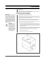
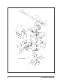
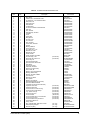
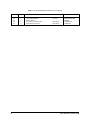
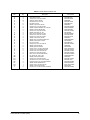
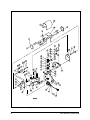
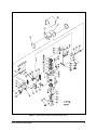
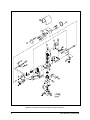
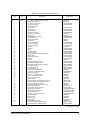
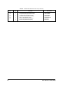
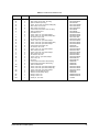
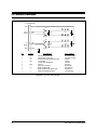
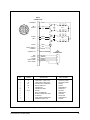
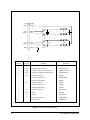
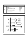
®
PT175-24P
PT180 Series
PT270 Series
PT280 Series
Light Duty Pan/Tilt
Maintenance/
Service Manual
C323SM (9/98)
Pelco • 3500 Pelco Way, Clovis • CA 93612-5699 USA • www.pelco.com
In North America and Canada: Tel (800) 289-9100 or FAX (800) 289-9150
International Customers: Tel (1-559) 292-1981 or FAX (1-559) 348-1120
CONTENTS
Section
Page
1.0 GENERAL .................................................................................................. 3
1.1 IMPORTANT SAFEGUARDS AND WARNINGS ............................... 3
2.0 DESCRIPTION .......................................................................................... 4
2.1 MODELS ............................................................................................ 4
3.0 MAINTENANCE ......................................................................................... 5
3.1 RESETTING POTENTIOMETERS .................................................... 5
3.2 SERVICING DRIVE CHAIN ASSEMBLIES ....................................... 6
3.2.1 Tightening Drive Chains .......................................................... 6
3.2.2 Chain Drive Lubrication .......................................................... 6
4.0 EXPLODED ASSEMBLY DIAGRAMS ....................................................... 7
5.0 WIRING DIAGRAMS ................................................................................ 22
6.0 WARRANTY AND RETURN INFORMATION ........................................... 28
LIST OF ILLUSTRATIONS
Figure
1
2
3
4
5
6
7
8
9
10
11
12
13
14
Page
Sealant Locations .............................................................................. 5
Servicing the PT175-24P and PT180 Series ..................................... 6
Servicing the PT270/PT280 Series .................................................... 6
PT175-24P Exploded Assembly Diagram .......................................... 7
PT180 Series Exploded Assembly Diagram ..................................... 10
PT270 Series Exploded Assembly Diagram ..................................... 14
PT280 Series Exploded Assembly Diagram (Parts) ......................... 17
PT280 Series Exploded Assembly Diagram (Hardware) .................. 18
PT175-24P Wiring Diagram .............................................................. 22
PT180 Series Wiring Diagram .......................................................... 23
PT270 Series Wiring Diagram .......................................................... 24
PT280-24P/PT280-24SL Wiring Diagram ......................................... 25
PT280-24P/PP Wiring Diagram ........................................................ 26
PT280-24SL/PP Wiring Diagram ...................................................... 27
LIST OF TABLES
Table
A
B
C
D
E
F
G
H
I
Page
PT175-24P Mechanical Parts List ..................................................... 8
PT175-24P Hardware List .................................................................. 9
PT180 Series Mechanical Parts List ................................................. 11
PT180 Series Hardware List ............................................................. 13
PT270 Series Mechanical Parts List ................................................. 15
PT270 Series Hardware List ............................................................. 16
PT280 Series Mechanical Parts List ................................................. 19
PT280 Series Hardware List ............................................................. 21
PT280 Series Electrical Parts List .................................................... 25
REVISION HISTORY
Manual #
C323SM
2
Date
9/98
Comments
Original version.
Pelco Manual C323SM (9/98)
1.0 GENERAL
1.1 IMPORTANT SAFEGUARDS AND WARNINGS
Prior to installation and use of this product, the following WARNINGS should be
observed.
1.
Installation and servicing should only be done by qualified service personnel
and conform to all local codes.
2.
Unless the unit is specifically marked as a NEMA Type 3, 3R, 3S, 4, 4X, 6, or
6P enclosure, it is designed for indoor use only and it must not be installed
where exposed to rain and moisture.
3.
The weight of the camera, lens, and enclosure shall not exceed 15 lb (6.81 kg)
for the PT270 Series and PT280 Series or 20 lb (9.08 kg) for the PT175-24P
or PT180 Series.
4.
Only use replacement parts recommended by Pelco.
5.
After replacement/repair of this unit’s electrical components, conduct a resistance measurement between line and exposed parts to verify the exposed
parts have not been connected to line circuitry.
6.
The installation method and materials should be capable of supporting four
times the weight of the enclosure, pan/tilt, camera and lens combination.
The product and/or manual may bear the following marks:
This symbol indicates that dangerous voltage constituting a
risk of electric shock is present within this unit.
This symbol indicates that there are important operating and
maintenance instructions in the literature accompanying this
unit.
CAUTION:
RISK OF
ELECTRIC SHOCK.
DO NOT OPEN.
CAUTION:
TO REDUCE THE RISK OF ELECTRICAL SHOCK,
DO NOT REMOVE COVER. NO USERSERVICEABLE PARTS INSIDE. REFER SERVICING
TO QUALIFIED SERVICE PERSONNEL.
Please thoroughly familiarize yourself with the information
in this manual prior to installation and operation.
Pelco Manual C323SM (9/98)
3
2.0 DESCRIPTION
The PT175-24P is a light duty, indoor/outdoor pan and tilt unit capable of handling
enclosure, camera and lens combinations weighing up to 20 lb. The PT175-24P is
equipped with 24 VAC motors.
The PT180-24P and PT180-24SL are light duty, indoor pan/tilt units capable of
handling all enclosure, camera and lens combinations up to 20 lb (9.08 kg) in weight.
The PT180-24P and PT180-24SL are equipped with 24 VAC motors.
The PT180-24SL has the added feature of 360° pan rotation and both pan/tilts are
pre-wired for all control functions: pan/tilt, motorized zoom lens, camera power and
video. All connections are made at the input connector, eliminating the need for
wiring harnesses.
Pan/tilts in the PT270 Series are engineered to accommodate lightweight CCTV
cameras and are capable of handling enclosure, camera and lens combinations
weighing up to 15 lb (6.8 kg). The pan/tilts feature long-life 24 VAC, 120 VAC or 230
VAC motors.
The pan/tilts of the PT280-24 Series are mini-size, light duty, indoor units capable
of supporting loads up to 15 lb (6.8 kg). They operate on 24 VAC.
They are factory pre-wired for pan and tilt control functions, motorized zoom lens
operation, camera power, and video. All connections are made at the input/output
connectors, eliminating the need for wiring harnesses. This greatly reduces installation time, while increasing reliability and serviceability.
2.1 MODELS
4
PT175-24P
Light duty pan/tilt, 24 VAC
PT180-24P
Light duty pan/tilt, 24 VAC
PT180-24SL
Light duty pan/tilt with SL option (360° pan rotation), 24 VAC
PT270P
Light duty “mini” pan/tilt, 120 VAC
PT270-24P
Light duty “mini” pan/tilt, 24 VAC
PT270P/230
Light duty “mini” pan/tilt, 230 VAC
PT280-24P
Mini-size, light duty pan/tilt, 24 VAC
PT280-24SL
Mini-size, light duty pan/tilt with 360° pan rotation, 24 VAC
PT280-24P/PP
Same as PT280-24P except with preset positioning capabilities.
PT280-24SL/PP
Same as PT280-24SL except with preset positioning capabilities.
Pelco Manual C323SM (9/98)
3.0 MAINTENANCE
PT175-24P Only
If your pan/tilt is installed in an inverted position, apply RTV silicone sealant to the
areas circled in Figure 1 after you reinstall the cover.
3.1 RESETTING POTENTIOMETERS
IMPORTANT: Be very careful
when resetting potentiometer
switches. Be sure that the pan/tilt
has been centered between maximum pan and tilt travel, regardless
of the adjustable limit stops. Failure to observe caution when resetting potentiometers could result in
damage to the preset positioning
ability of the pan/tilt.
WARNING: NEVER
reposition the pan fixed
limit stop. Doing so
WILL DAMAGE the
wiring harness and, if
the pan/tilt has preset
positioning, COULD
cause the pan potentiometer to BREAK.
PT280-24P/PP and PT280-24SL/PP Models Only
Models with preset positioning (PP) use potentiometer switches that are factory set
to the full range of pan and tilt travel. Under normal operating conditions and at
routine service intervals they do not need adjusting.
Should your pan/tilt require any work on the drive mechanism other than routine
maintenance, perform the following procedure to reset the potentiometers.
To begin, remove the three screws on the front of the pan/tilt housing and lift the
cover to gain access to the pan and tilt motor assemblies.
1.
Remove the potentiometer gears and position the pan/tilt to the middle of its
maximum pan and tilt travel, regardless of the position of the adjustable limit
stops. That is, the tilt table should be level and the fixed limit stop should be
opposite the limit switch.
2.
Turn a potentiometer all the way in one direction until it stops, then observing
the number of turns, turn it back the other way until it stops. Rotate the potentiometer half the number of turns the other way to reach the center.
3.
Replace the potentiometer gear.
4.
Perform steps 2 and 3 for the other potentiometer.
➛
➛
➛
Figure 1. Sealant Locations
Pelco Manual C323SM (9/98)
5
3.2 SERVICING DRIVE CHAIN ASSEMBLIES
Inspect the pan/tilt unit every six months to ensure trouble-free operation and an
extended product life. Harsh environments and/or continuous motion applications
may require more frequent maintenance.
Please read all of the instructions that follow before servicing the pan/tilt.
To begin, remove the three screws on the front of the pan/tilt housing and lift the
cover to gain access to the pan and tilt motor assemblies.
3.2.1 Tightening Drive Chains
Check the pan and tilt drive chains for tension. A movement of 1/32 of an inch to 3/32
of an inch in the chains is acceptable. If the movement of a chain exceeds 3/32 of an
inch, adjust the chain as follows:
1.
Loosen the screws securing the motor to the mounting frame.
2.
Pry on the motor to apply tension to the chain. Do not over-tension the drive
chain.
3.
Keep tension on the chain while tightening the screws.
3.2.2 Chain Drive Lubrication
Sprockets, chains, and gears should be well greased. If necessary, lubricate the
pan and tilt gears, sprockets, and chains as follows with a high-quality grease capable of withstanding temperatures from -50° to 170°F (-46° to 77°C). Do the following:
1.
Liberally apply grease to the pan and tilt gears, chains, and sprockets (refer to
Figure 2 or 3).
2.
Operate the pan and tilt motors to spread the grease across the parts.
3.
Apply additional grease if necessary.
4.
Reinstall the cover. If the pan/tilt is installed outdoors in an inverted position,
apply RTV silicone sealant as shown in Figure 1.
APPLY GREASE
TO THESE
LOCATIONS
APPLY GREASE
TO THESE
LOCATIONS
00063
Figure 2. Servicing the PT175-24P and PT180 Series
6
Figure 3. Servicing the PT270/PT280 Series
Pelco Manual C310M-E (8/98)
4.0 EXPLODED ASSEMBLY DIAGRAMS
Figure 4 . PT175-24P Exploded Assembly Diagram
Pelco Manual C323SM (9/98)
7
Table A. PT175-24P Mechanical Parts List
8
Item
Quantity
1
2
3
4
5
6
7
8
9
10
11
12
13
14
15
16
17
18
19
20
21
22
23
24
25
26
27
28
29
30
31
32
33
34
35
36
37
38
39
40
41
42
43
44
45
46
47
48
49
1
1
1
1
1
1
1
1
1
1
1
1
1
2
1
1
2
1
2
1
1
1
1
1
1
1
1
1
1
1
2
1
1
1
3
1
1
2
4
1
9
1
8
4
4
1
2
1
1
Description
Tilt Side Plate
Pan Side Plate
Bottom Plate
Tilt Shaft Assembly
Tilt Table
Cover
Pull Up Bar
Tilt Gear
Hub Tilt Gear
Plate Backup Tilt Gear
Body Spacer
Pan Limit Pin
Tilt Limit Pin
Tilt Limit Stops
Bracket Pan Limit
Bracket Tilt Limit
Cover Plate Tilt Shaft
Spindle
Bearing FB810-5
Connector Mating Assy 9-Pin (not shown)
Chain Assy Tilt
Chain Assy Pan
Motor Plate
Sprocket Motor Shaft
Sprocket Pan
Bracket Pan Motor
Sprocket Worm Gear Shaft
Worm Gear Shaft
Tilt Motor Gearhead
Nut, spindle
Bearing Pan Spindle
Pan Motor & Gearhead Assy, 24 VAC
Sprocket 25B20-3/8 W/SS
Tilt Motor Only, 24 VAC
Limit Stop, Pan
Bearing B46-2
Tilt Worm Gear
Bearing Cage Only A05CN
Bearing Washer Only
Connector 9-Pos Recep (not shown)
Connector Crimp Pins, CPC (not shown)
Bushing FB46-3
Sleeving PVC 105-16 X inch (not shown)
Switch 1SM1
Switch Actuator w/Insulator
Terminal Strip, 9-Pin (not shown)
Electrovert Sp-1/4CP x Foot (not shown)
Capacitor 15MF 100V (not shown)
Capacitor 60MF 200V (not shown)
Part Number
1554038COMP
1554039COMP
1554055COMP
1551009COMP
1554037COMP
1554041COMP
1554042COMP
1554144COMP
6804049COMP
1554046COMP
1554047COMP
1554049COMP
1554049TCOMP
1554050COMP
1554051COMP
1554052COMP
1554053COMP
1554054ACOMP
1556004
1751000COMP
1751002COMP
1751003COMP
1751062WA
17512004
1754001COMP
1754002COMP
1754022COMP
1754064COMP
1758006
25010002
2506000
2508001
27012008
5708007
58010006
5806005
7712006
776001
776002
CON206705-1
CON66103-2
PT250010005
SLV16105N
SWI1SM1
SWIJS138B
TRS2009
ZSSPIROBAND
CAPU0015.0/100N
CAPU0060.0/200N
Pelco Manual C323SM (9/98)
Table B. PT175-24P Hardware List
Item
Quantity
A
B
C
D
E
F
G
H
I
J
K
L
M
N
O
P
Q
R
S
T
U
4
2
2
1
4
2
1
6
1
—
1
2
11
10
12
8
1
4
4
4
2
Pelco Manual C323SM (9/98)
Description
Snap Ring
Pin Dowel 1/8" X 5/8" Hardened Steel
Pin Dowel 1/8" X 1/2" Hardened Steel
Pin, taper #1 x 1-1/4
Gasket,1/8" X 1/2" X FT
Grommet #AN931-3-5
Bolt, 1/4-20 x 5/8" Hex C/S SS
Bolt, 1/4-20 x 3/4" flat HdPhil SS
Washer, internal star, 1/4" SS
Not used
Set Screw 10-32 x 3/16” Soc Knur Blk
Set Screw 10-32 x 5/16” Soc Knur Blk
Screw, 10-32 x 1/2" Hex Soc Hd SS
Split lock washer, #10 SS
Flat washer #10 x .064SS
Screw, 2-56 x 7/16" Pan Phil SS
Washer, flat, 3/16 USS Spl-Size Pltd
Screw 4-40 x 1/4” Pan Phil SS
Screw, 4-40 x 3/8" Pan Phil SS
Washer, internal star #4 SS
Washer, flat 1/2”
Part Number
15510000
15510001
15510003
17510000
EH550010030
GRO2172N
ZH1/420X.625CH
ZH1/420X.750SFS
ZH1/4LWSIS
ZH10-32X.187S
ZH10-32X.312S
ZH10-32X.500CS
ZH10LWSSL
ZH204X436X60C
ZH2-56X.437SPP
ZH260X562X65C
ZH4-40X.250SSP
ZH4-40X.375SPP
ZH4LWSIS
ZH515X875X62
9
Figure 5. PT180 Series Exploded Assembly Diagram
10
Pelco Manual C323SM (9/98)
Table C. PT180 Series Mechanical Parts List
Item
Qty
1
2
3
4
5
6
7
8
9
10
11
12
13
14
15
16
17
18
19
20
21
22
23
24
25
26
27
28
29
30
31
32
33
34
35
36
37
38
39
40
41
42
43
44
45
46
47
48
49
50
51
52
53
54
55
56
57
58
59
60
61
62
4
4
2
1
1
1
1
2
1
1
1
1
1
1
1
1
1
2
2
1
2
1
1
1
1
4
4
1
2
1
1
1
1
1
1
1
1
2
4
1
1
1
1
2
1
1
3
1
1
1
1
2
14
1
1
1
1
2
1
1
1
1
Description
Ring, Snap
Gasket 1/8” x 1/2” #G207N x Feet
Pin Dowel 1/8” x 1/2” Hardened Steel
Plate, Side, Tilt
Plate, Side, Pan
Plate, Bottom
Tilt Shaft Assy
Pin, Dowel 1/8”x5/8” Hardened Steel
Gear Tilt
Hub, Tilt Gear
Plate, Backup, Tilt Gear
Tilt Table
Cover
Pull-Up Bar
Body Spacer
Pin, Pan Limit
Pin, Tilt Limit
Stop, Tilt Limit
Cover Plate, Tilt Shaft
Spindle
Bearing FB810-5
Chain Assy, Pan
Pin, Taper, #3 x 1-1/4”
Bracket, Pan Limit
Bracket, Tilt Limit
Switch #1SM1
Switch Actuator w/Insulator
Terminal Strip, 9-Pin
Electrovert SP-1/4CP x FT
Chain Assy, Tilt
Sprocket, Motor Shaft
Sprocket, Worm Gear Shaft
Plate Motor
Shaft, Worm Gear
Gearhead, Tilt Motor
Motor Only, Tilt (24 VAC)
Worm Gear, Tilt
Bearing, Cage only #A05CN
Bearing, Washer Only
Bushing, Tilt Shaft, FB46-3
Sprocket, Pan
Bracket, Pan Motor
Nut, Spindle
Bearing, Pan Spindle
Motor W/Gearhead, Pan (24 VAC)
Sprocket, 25B20-3/8 W/SS
Limit Stop, Pan (Except PT180-24SL)
Capacitor 15mf 100v
Capacitor 60mf 200v
Connector CPC 14 Pos Pin Plug
Connector CPC Cable Clamp
Lug, Spade 16-20 ga.
Connector CPC Pin
Connector Boot
Connector Mate Assy 14 Pin Skt Cble
Connector 6 Pos Fem
Connector BNC Crimp for RG174
Grommet # AN931-3-5
Clamp, Cable
Ring, Slip #AC4023-18GA w/24” Leads
Plate, Slip Ring Adapter
Bracket, Slip Ring
Part Number
(Not shown)
(Not shown)
(Not shown)
(Not shown)
(Not shown)
(Not shown)
(Not shown)
(Not shown)
(Not shown)
(Not shown)
(Not shown)
(Not shown)
(SL only)
(SL only)
(SL only)
15510000
EH550010030
15510003
1554038COMP
1804000COMP
1554055COMP
1551009COMP
15510001
1554144COMP
6804049COMP
1554046COMP
1554037COMP
1554041COMP
1554042COMP
1554047COMP
1554049COMP
1554049TCOMP
1554050COMP
1554053COMP
2704105COMP
1556004
1751003COMP
17510001
1554051COMP
1554052COMP
SWI1SM1
SWIJS138B
TRS2009
ZS-SPIROBAND
1751002COMP
17512004
1754022COMP
1751062WA
1754064COMP
1758006
5708007
7712006
776001
776002
PT250010005
1804001COMP
1754002COMP
25010002
2506000
2508001
27012008
58010006
CAPU0015.0/100N
CAPU0060.0/200N
CON206044-1
CON206070-1
CON52929-1
CON66102-7
CON9779-513-8
CONA14S
CONMAB6100
CONCPM88-174
GRO2172N
2504007COMP
28010000
SL28004000COMP
SL28004001COMP
Continued on next page
Pelco Manual C323SM (9/98)
11
Table C. PT180 Series Mechanical Parts List (continued)
12
Item
Qty
63
64
65
66
67
1
1
1
1
1
Description
Cover, Slip Ring Adapter
Mount, PM200C/SB3-1
Bearing #B46-2
Connector, Lens Mating 6 Pos
Strain Relief #1147 Heyco
Part Number
(SL only)
(SL only)
(Not shown)
(Not shown)
SL28004002COMP
PM200C4000COMP
5806005
CONMAS6100
STRSP5N-4
Pelco Manual C323SM (9/98)
Table D. PT180 Series Hardware List
Item
Qty
A
B
C
D
E
F
G
H
I
J
K
L
M
N
O
P
Q
R
S
T
U
V
W
X
Y
Z
AA
BB
CC
DD
EE
FF
GG
HH
II
4
4
10
4
6
6
2
12
2
3
3
4
3
3
8
4
1
6
3
3
11
11
2
8
4
6
1
4
2
1
3
2
1
1
2
Description
Acorn Nut, 6-32 SS
Screw, 8-32 x 1/2” Soc C/S SS
Split lock washer, #8 SS
Set Screw, 6-32 x 3/4” SS
Hex Nut, 6-32 SS
Washer, internal star, #6 SS
Screw, 8-32 x 1/2” Pan Phil SS
Washer, Flat #10 AN960C-10 x .064 SS
Washer, Flat 1/2 AN-960-816
Screw, 8-32 x 3/8” Pan Phil SS
Washer, Split lock, 1/4” SS
Bolt, 1/4-20 x 5/8” Hex C/S SS
Screw, 8-32 x 5/8” Soc C/S SS
Screw, 6-32 x 3/8” Soc C/S SS
Washer, internal star, #8 SS
Washer, flat, 3/16 USS Spl-Size Pltd
Washer, internal star, 1/4” SS
Hex nut, 8-32 SS
Screw, 8-32 x 3/4”, Pan Phil SS
Washer, split lock #6 SS
Washer, split lock #10 SS
Screw, 10-32 x 1/2” Soc Hd C/S SS
Screw, 6-32 x 3/4” flat M/S Phil SS
Screw, 2-56 x 7/16” Pan Phil SS
Screw, 4-40 x 3/8” Pan Phil SS
Bolt, 1/4-20 x 3/4” flat Phil M/S SS
Pin, spring roll, 3/32” x 3/8”
Washer, internal star #4SS
Screw, 6-32 x 3/8” Pan Phil SS
Set Screw, 6-32 x 3/16” Soc Knur Blk
Screw, 8-32 X 2-1/4” round head slotted
Washer, flat #6 AN960C-6 SS
Screw, 10-32 x 3/8” Pan Phil SS
Washer, internal star #10 SS
Screw, 6-32 x 3” Pan Phil Full Thread SS
Pelco Manual C323SM (9/98)
Part Number
ZH6-32NUTCA
ZH8-32X.500CS
ZH8LWSSL
ZH6-32X.750SS
ZH6-32NUTSH
ZH6LWSIS
ZH8-32X.500SPP
ZH204X436X60C
ZH515X875X62
ZH8-32X.375SPP
ZH1/4LWSSL
ZH1/420X.625CH
ZH8-32X.625CS
ZH6-32X.375CS
ZH8LWSIS
ZH260X562X65C
ZH1/4LWSIS
ZH8-32NUTSH
ZH8-32X.750SPP
ZH6LWSSL
ZH10LWSSL
ZH10-32X.500CS
ZH6-32X.750SFS
ZH2-56X.437SPP
ZH4-40X.375SPP
ZH1/420X.750SFS
ZHPIN3/32X3/8R
ZH4LWSIS
ZH6-32X.375SPP
ZH6-32X.187S
ZH8-32X2.25CRS
ZH148X375X32C
ZH10-32X.375SPP
ZH10LWSIS
ZH6-32X3.00SRS
13
Figure 6. PT270 Series Exploded Assembly Diagram
14
Pelco Manual C323SM (9/98)
Table E. PT270 Series Mechanical Parts List
Item
Qty
1
2
3
4
5
6
7
8
9
10
11
12
13
14
15
16
17
18
19
20
21
22
23
24
25
26
27
4
1
1
2
1
2
1
1
1
1
2
2
1
1
1
1
1
1
1
1
1
1
1
1
1
1
1
1
1
1
1
1
3
1
1
2
1
1
1
1
4
4
1
28
29
30
31
32
33
34
35
36
37
38
39
Description
Snap ring, #Q2-18
Pin pan limit
Pin tilt limit
Tilt limit stop
Bracket tilt limit
Cover plate, tilt
Pin, #1 x 1-1/4" taper
Nut, spindle
Clamp cable
Spacer, tilt collar
Bearing, pan spindle
Bearing, Tilt FB68-31/4
Plate, side tilt
Bottom plate
Side plate, pan
Tilt shaft assembly
Pan chain assembly
Tilt chain assembly
Sprocket, 25B20-3/8 w/SS
Tilt table
Cover
Bracket, pan/tilt motor
Sprocket motor
Pan limit bracket
Spindle
Sprocket
Pan motor, 2 rpm, 24 VAC (PT270-24P)
Pan motor, 2 rpm, 120 VAC (PT270P)
Pan motor, 2 rpm, 230 VAC (PT270P/230)
Pan motor bracket
Pan motor spacer
Sprocket, pan spindle
Pan limit stop
Connector CPC cable clamp
1/4" Rubber grommet
Neoprene grommet
Tilt Motor, 1rpm, 120 VAC (PT270P)
Tilt Motor, 1rpm, 24 VAC (PT270-24P)
Tilt Motor, 1 rpm, 230 VAC (PT270/230)
Spacer, 5/16 dia. x 1.25
Switch
Switch actuator w/insulator
Term strip, 7 pin
Pelco Manual C323SM (9/98)
Part Number
15510000
1554049COMP
1554049TCOMP
1554050COMP
1554052COMP
1554053COMP
17510000
25010002
2504007COMP
2504015COMP
2506000
2506001
2704001COMP
2704100COMP
2704102COMP
2701002COMP
2701003COMP
2701004COMP
27012008
2704003COMP
2704004COMP
2704006COMP
2704010COMP
2704051COMP
2704105COMP
28012010
2804001COMP
2508000
2508220
2804012COMP
2804013COMP
2804019COMP
58010006
CON206966-1
GRO2170
GRO2172N
2708000
PS78001
2708220
SPA8548
SWI1SM1
SWIJS138B
TRS2007
15
Table F. PT270 Series Hardware List
16
Item
Qty
A
B
C
D
E
F
G
H
I
J
K
L
M
N
O
P
Q
R
S
T
U
V
X
Y
Z
AA
BB
CC
DD
4
2
6
8
8
8
1
1
6
4
1
6
2
4
2
3
2
2
4
4
3
3
3
1
4
1
1
1
1
Description
Bolt, 1/4-20 x 5/8, phil flat, SS
Screw, 10-32 x 1/2", socket head, C/S, SS
Screw, 10-32 x 1/2", socket head, SS
Split lock washer, #10, SS, medium
Flat washer, #10, SS
Screw, 2-56 x 7/16", pan phil, SS
Set screw, 10-32 x 3/8", socket knurl, black
Set screw, 10-32 x 3/16", socket knurl, black
Screw, 4-40 x 3/8", pan phil
Screw, 4-40 x 3/8", pan phil
Screw, 4-40 x 5/8", pan phil, SS
#4 Internal tooth lockwasher, SS
Set screw, 6-32 x 3/16", socket knurl, black
Screw, 6-32 x 1/4", pan phil, SS
Screw, 6-32 x 3/8", pan phil, SS
Screw, 6-32 x 1/2", socket
Set screw, 6-32 x 3/4", socket cap
Screw, 6-32 x 2", pan phil, SS
Nut, 6-32 x 2", pan phil, SS
Nut, hex, 6-32, SS
#6 Internal tooth lock washer, SS
Split lock washer, #6, SS med
Screw, 8-32 x 3/8", pan phil, SS
Screw, 8-32 x 5/8", pan phil, SS
Internal star washer, #8, SS
Pin roll, 3/32" x 1/2"
Pin roll, 3/32" x 3/4"
Pin dowel, 1/8" x 5/8", hardened steel
Set screw, 10-32 x 5/16", knurl, black
Part Number
ZH1/4-20X.625SFS
ZH10-32X.437CS
ZH10-32X.500CS
ZH10LWSSL
ZH204X.436X60C
ZH2-56X.437SPP
Supplied with #19
ZH10-32X.187S
ZH4-40X.250SPP
ZH4-40X.375SPP
ZH4-40X.625SPP
ZH4LWSIS
ZH6-32X.187SS
ZH6-32X.250SPP
ZH6-32X.375SPP
ZH6-32X.500CS
ZH6-32X.750SS
ZH6-32X2.00SPS
ZH6-32NUTCA
ZH6-32NUTSH
ZH6LWSIS
ZH6LWSSL
ZH8032X.375SPP
ZH8032X.625SPP
ZH8LWSIS
ZHPIN3/32X1/2R
ZHPIN3/32X3/4R
15510001
ZH10-32X.312S
Pelco Manual C323SM (9/98)
Figure 7. PT280 Series Exploded Assembly Diagram (Parts)
Pelco Manual C323SM (9/98)
17
Figure 8. PT280 Series Exploded Assembly Diagram (Hardware)
18
Pelco Manual C323SM (9/98)
Table G. PT280 Series Mechanical Parts List
Item
Qty
1
4
2
1
1
1
2
1
2
1
1
1
1
2
2
1
1
1
1
1
1
1
1
1
1
1
1
1
1
1
1
1
1
1
3
1
2
1
1
4
2
4
2
1
1
1
1
1
1
1
1
1
1
1
1
1
1
1
2
3
4
5
6
7
8
9
10
11
12
13
14
15
16
17
18
19
20
21
22
23
24
25
26
27
28
29
30
31
32
33
34
35
36
37
38
39
40
41
42
43
44
45
46
47
Description
Snap ring (P, P/PP, and SL/PP models)
Snap ring (SL model)
Pan limit pin (P and SL)
Pan limit pin (P/PP)
Not used (SL/PP)
Tilt limit pin
Tilt limit stop
Tilt limit bracket
Tilt table cover plate
Tapered pin (except SL)
Spindle nut
Cable clamp (P and P/PP)
Tilt collar spacer
Pan spindle bearing
Tilt bearing
Tilt shaft assembly
Pan chain assembly
Tilt chain assembly
Sprocket
Tilt table
Cover
Tilt motor bracket
Motor sprocket
Pan limit bracket (except SL/PP model)
Bottom plate
Side plate, pan side
Spindle
Sprocket
Pan motor, 2 RPM, 24 VAC
Side plate, tilt side (P and SL)
Side plate, tilt side (P/PP and SL/PP)
Pan motor bracket
Pan motor spacer
Pan spindle sprocket
Pan limit stop (P and P/PP)
6-position connector (P and SL)
Neoprene grommet
Tilt motor, 1 RPM, 24 VAC
Spacer (except P/PP model)
Switch (P, P/PP, and SL)
Switch (SL/PP)
Switch Actuator with Insulator (P, P/PP, SL)
Switch Actuator with Insulator (SL/PP)
7-pin terminal strip (P and SL)
9-pin terminal strip, (P/PP and SL/PP)
Gland (SL and SL/PP)
Nut for gland (SL and SL/PP)
Bracket (SL and SL/PP)
Slip ring bracket (SL/PP)
Slip ring bracket (SL)
Slip ring cover (SL and SL/PP)
Slip ring (SL/PP)
Slip ring (SL)
Gear (SL/PP)
Gear (P/PP)
Gear (P/PP and SL/PP)
Pan potentiometer bracket (P/PP)
Pan potentiometer bracket (SL/PP)
Part Number
15510000
15510000
1554049COMP
2804003COMP
1554049TCOMP
1554050COMP
1554052COMP
1554053COMP
17510000
25010002
2504007COMP
2504015COMP
2506000
2506001
2701002COMP
2701003COMP
2701004COMP
27012008
2704003COMP
2704004COMP
2704006COMP
2704010COMP
2704051COMP
2704100COMP
2704102COMP
2704105COMP
28012010
2804001COMP
2804002COMP
2804102COMP
2804012COMP
2804013COMP
2804019COMP
58010006
CONMAB6100
GR02172N
PS78001
SPA8548
SWI1SM1
SWI1SM1
SWIJS138B
SWIJS138B
TRS2007
TRS2009
EH400010003
EH400010004
PM200C4000COMP
SL28004101COMP
SL28004001COMP
SL28004100COMP
250010000
28010000
28010016
PT250010002
28010017
2804014COMP
2804117COMP
Continued on next page
Pelco Manual C323SM (9/98)
19
Table G. PT280 Series Mechanical Parts List (continued)
20
Item
Qty
48
49
50
51
52
53
1
1
1
1
1
1
2
Description
Tilt potentiometer bracket (P/PP & SL/PP)
Pan spindle preset gear (P/PP & SL/PP)
Tilt shaft preset gear (P/PP & SL/PP)
9-position connector (P/PP and SL/PP)
Dual arm potentiometer (SL/PP)
Precision 10K potentiometer (SL/PP)
Precision 10K potentiometer (P/PP)
Part Number
2804015COMP
2804016COMP
2804020COMP
CON206705-1
POTDARM010.0K
POT010.0K
POT010.0K
Pelco Manual C323SM (9/98)
Table H. PT280 Series Hardware List
Item
Qty
A
B
C
D
E
F
G
H
I
J
4
3
3
1
2
6
1
8
8
8
4
1
1
6
4
1
6
2
4
4
2
3
4
2
4
4
7
3
3
6
3
1
7
4
1
1
1
K
L
M
N
O
P
Q
R
S
T
U
V
W
X
Y
Z
AA
BB
CC
DD
EE
FF
GG
Description
Bolt, 1/4-20 x 5/8", flat head, Phillips
Allen screw, 1/4-20 x 5/8" (SL Only)
Split lock washer (SL Only)
Screw, 10-32 x 3/8", pan head, Phillips (SL)
Allen screw, 10-32 x 7/16"
Allen screw, 10-32 X 1/2"
Internal tooth lock washer, #10 (SL Only)
Split lock washer, #10
Flat washer, #10
Screw, 2-56 x 1/4", pan head, Phillips
Screw, 2-56 x 1/4", pan head, Phillips (SL)
Set screw, 10/32 x 1/8"
Set screw, 10/32 x 3/16"
Screw, 4-40 x 1/4", pan head, Phillips
Screw, 4-40 x 3/8", pan head, Phillips (PP)
Screw, 4-40 x 5/8", pan head, Phillips
Internal tooth lock washer, #4
Set screw, 6-32 x 3/16"
Screw, 6-32 x 1/4", pan head, Phillips
Allen screw, 6-32 x 3/8"
Screw, 6-32 x 3/8", pan head, Phillips
Allen screw, 6-32 x 1/2"
Set screw, 6-32 x 3/4"
Screw, 6-32 x 2", pan head, Phillips
Acorn nut, 6-32
Nut, 6-32
Internal tooth lock washer, #6 (PP Only)
Internal tooth lock washer, #6 (P Only)
Split lock washer, #6
Screw, 8-32 x 3/8", pan head, Phillips (SL)
Screw, 8-32 x 3/8", pan head, Phillips (P)
Screw, 8-32 x 5/8", pan head, Phillips
Washer, Internal Star (SL Only)
Washer, Internal Star (P Only)
Roll pin, 3/32" x 1/2"
Roll pin, 3/32" x 1/2"
Dowel pin, 1/8" x 5/8"
Pelco Manual C323SM (9/98)
Part Number
ZH1/420X.625SFS
ZH1/420X.625CH
ZH1/4LWSSL
ZH10-32X.375SPP
ZH10-32X.437CS
ZH10-32X.500CS
ZH10LWSIS
ZH10LWSSL
ZH204X436X60C
ZH2-56X.437SPP
ZH2-56X.437SPP
ZH10-32X.187S
ZH3/8-24X.375SS
ZH4-40X.250SPP
ZH4-40X.375SPP
ZH4-40X.625SPP
ZH4LWSIS
ZH6-32X.187S
ZH6-32X.250SPP
ZH6-32X.375CS
ZH6-32X.375SPP
ZH6-32X.500CS
ZH6-32X.750SS
ZH6-32X2.00SPS
ZH6-32NUTCA
ZH6-32NUTSH
ZH6LWSIS
ZH6LWSIS
ZH6LWSSL
ZH8-32X.375SPP
ZH8-32X.375SPP
ZH8-32X.375SPP
ZH8LWSIS
ZH8LWSIS
ZHPIN3/32X1/2R
ZHPIN3/32X3/4R
1510001
21
5.0 WIRING DIAGRAMS
P1 CONNECTOR
COM
1
BRN
S1
LEFT
RIGHT
3
7
RED
BLU
C1
M1
S2
S3
UP
DOWN
6
5
YEL
ORG
GND
8
GRN
QTY
SYMBOL
1
1
1
1
1
4
4
1
9
1
C1
C2
M1
M2
—
S1-S4
—
P1
—
—
C2
M2
S4
DESCRIPTION
CAPACITOR, 60 MF, 200V
CAPACITOR, 15 MF, 100V
PAN MOTOR AND GEARHEAD ASSY
TILT MOTOR
TILT MOTOR GEARHEAD
SWITCH
SWITCH ACTUATOR
BASE CONNECTOR
BASE CONNECTOR CRIMP PINS
MATING CONNECTOR ASSY
PART NUMBER
CAPU0060.0/200N
CAPU0015.0/100N
2508001
5708007
1758006
SWI1SM1
SWIJS138B
CON206705-1
CON66103-2
1751000COMP
Figure 9. PT175-24P Wiring Diagram
22
Pelco Manual C323SM (9/98)
INPUT
CONNECTOR
1
4
2
5
8
BRN
LEFT
RIGHT
3
7
ORG
VIO
7
10
13
1
3
6
9
12
COMMON
S1
C1
M1
C2
M2
11
S2
14
DOWN
LEFT
5
6
GRAY
BLUE
S3
S4
VIDEO
2
RED
VIDEO SHEILD
CAMERA
4
9
YEL
WHITE
CAMERA AC
14
W/YEL
J2
LENS
CONNECTOR
IRIS
FOCUS
ZOOM
LENS COMM
SFTY GRND
10
11
12
13
8
BLACK
W/BRN
W/RED
W/ORG
GREEN
1
2
3
4
5
QTY
SYMBOL
1
1
1
1
1
14
4
1
1
1
1
1
C1
C2
M1
M2
J2
–
S1-S4
–
–
–
–
–
DESCRIPTION
CAPACITOR, 15 MFD, 100V
CAPACITOR, 60 MFD, 200V
PAN MOTOR w/ GEARHEAD
MOTOR (ONLY)TILT
CONNECTOR
CONNECTOR PINS
SWITCH
INPUT CONNECTOR
MATING CONNECTOR ASSY
ACTUATOR
LENS MATING CONNECTOR
GEARHEAD (ONLY) TILT
PART NUMBER
CAPU0015.0/100N
CAPU0060.0/200N
2508001
5708007
CONMAB6100
CON66102-7
SWI1SM1
CON206044-1
CONA14S
SWIJS138B
CONMAS6100
1758006
Figure 10. PT180 Series Wiring Diagram
Pelco Manual C323SM (9/98)
23
P1 CONNECTOR
COM
1
BRN
S1
LEFT
RIGHT
3
7
RED
BLU
C1
M1
S2
S3
UP
DOWN
6
5
YEL
ORG
GND
8
GRN
C2
M2
S4
Quantity
Symbol
Description
2
C1-C2
Capacitor .68/400 (PT270P)
CAPU000.68/400
2
C1-C2
Capacitor 15 MFD 100V (PT270-24P)
CAPU0015.0/100N
2
C1-C2
Capacitor 0.22 MFD 600V (PT270P/230)
CAPU000.22/600
1
M1
Pan Motor (PT270P)
2508000
Pan Motor (PT270-24P)
2804001COMP
Pan Motor (PT270P/230)
2508220
Tilt Motor (PT270P)
2708000
Tilt Motor (PT270-24P)
PS78001
Tilt Motor (PT270P/230)
2708220
9 Pin Male Connector
CON206705-2
Switch
SWI1SM1
1
M2
Part Number
1
P1
4
S1-S4
4
—
Actuator
SWIJS138B
1
—
Female Connector Assy.
1751000COMP
9
—
Connector Pins
CON66103-2
Figure 11. PT270 Series Wiring Diagram
24
Pelco Manual C323SM (9/98)
Table I. PT280 Series Electrical Parts List
Parts are for all models unless specified otherwise
Symbol
C1, C2
M1
M2
—
—
S1-S4
S1-S4
—
—
—
—
—
Description
Part Number
Capacitor, 15 MFD, 100 V
Pan motor
Tilt motor
6-pin male lens mating connector (P, SL models)
9-pin female lens mating connector assy (P/PP, SL/PP)
Switch
Actuator
14-pin female mating connector assembly (P, SL)
28-pin female mating connector assembly (P/PP, SL/PP)
Pan preset potentiometer (P/PP)
Pan preset potentiometer (SL/PP)
Tilt preset potentiometer (P/PP, SL/PP)
CAPU0015.0/100N
2804001COMP
PS78001
CONMAS6100
1751000COMP
SWI1SM1
SWIJS138B
CONA14S
CONA28S
POT010.0K
POTDARM010.0K
POT010.0K
INPUT
CONNECTOR
S1
ORG
VIO
C1
M1
C2
M2
S2
S3
GRY
BLU
S4
VIDEO
2
RED
VIDEO SHIELD
4
YEL
CAMERA POWER
9
WHT
CAMERA POWER
14
W/YEL
IRIS
10
BLK
FOCUS
11
W/BRN
1
2
ZOOM
12
W/RED
3
LENS COMM
13
W/ORG
4
SFTY GRND
8
GRN
5
BLK
BLK
LENS
CONNECTOR
Figure 12. PT280-24P/PT280-24SL Wiring Diagram
Pelco Manual C323SM (9/98)
25
28–PIN PAN/TILT SPINDLE CONNECTOR
COMMON
S1
LEFT
ORG
VIO
RIGHT
C1
M1
C2
M2
S2
S3
GRY
DOWN
UP
BLU
S4
1
PAN PRESET
19
2
GRN/WHT
PAN
3
TILT PRESET
20
2
VIO/WHT
1
TILT
3
PRESET GND
17
RED/WHT
P2
8
PRESET + 5V
18
BLK/WHT
6
FOCUS
11
WHT/BRN
3
ZOOM
12
WHT/RED
2
9–PIN
LENS COMM
13
WHT/ORG
4
LENS
IRIS
10
BLK
1
CONNECTOR
ZOOM PRESET
23
GRY/WHT
7
FOCUS PRESET
24
YEL/WHT
9
GROUND
8
GRN
5
CAM POWER
9
WHT
CAM POWER
14
WHT/YEL
VIDEO
2
RED
VIDEO SHIELD
4
YEL
BLK
BLK
COAX
Figure 13. PT280-24P/PP Wiring Diagram
26
Pelco Manual C323SM (9/98)
28–PIN PAN/TILT SPINDLE CONNECTOR
COMMON
ORG
LEFT
RIGHT
C1
M1
C2
M2
VIO
S1
DOWN
GRY
UP
BLU
SL (360˚) PRESET
25
S2
WHT/GRY
1
3
PAN PRESET
19
2
PAN
WHT/BLK/ORG
4
TILT PRESET
20
2
WHT/BLK/YEL
1
TILT
3
PRESET GND
17
WHT/BLK/RED
P2
8
PRESET + 5V
18
BLK/WHT
6
FOCUS
11
WHT/BRN
3
ZOOM
12
WHT/RED
2
9–PIN
LENS COMM
13
WHT/ORG
4
LENS
IRIS
10
BLK
1
CONNECTOR
ZOOM PRESET
23
WHT/VIO
7
FOCUS PRESET
24
WHT/GRN/BLK
9
GROUND
8
GRN
5
CAM POWER
9
WHT
CAM POWER
14
WHT/YEL
VIDEO
2
RED
VIDEO SHIELD
4
YEL
BLK
BLK
COAX
Figure 14. PT280-24SL/PP Wiring Diagram
Pelco Manual C323SM (9/98)
27
6.0 WARRANTY AND RETURN INFORMATION
WARRANTY
Pelco will repair or replace, without charge, any merchandise proved defective in material or workmanship for a period of one year after the date of shipment.
Exceptions to this warranty are as noted below:
• Five years on FT/FR8000 Series fiber optic products.
• Three years on Genex® Series products (multiplexers, server, and keyboard).
• Three years on Camclosure® and fixed camera models, except the CC3701H-2, CC3701H-2X,
CC3751H-2, CC3651H-2X, MC3651H-2, and CC3651H-2X camera models, which have a five-year
warranty.
• Two years on standard motorized or fixed focal length lenses.
• Two years on Legacy®, CM6700/CM6800/CM9700 Series matrix, and DF5/DF8 Series
fixed dome products.
• Two years on Spectra®, Esprit®, ExSite™, and PS20 Scanners, including when used in continuous
motion applications.
• Two years on Esprit® and WW5700 Series window wiper (excluding wiper blades).
• Eighteen months on DX Series digital video recorders, NVR300 Series network video recorders, and
Endura™ Series distributed network-based video products.months on DX Series digital video
recorders, NVR300 Series network video recorders, Endura™ Series distributed network-based video
products, and TW3000 Series twisted pair transmission products.
• One year (except video heads) on video cassette recorders (VCRs). Video heads will be covered for a
period of six months.
• Six months on all pan and tilts, scanners or preset lenses used in continuous motion applications
(that is, preset scan, tour and auto scan modes).
Pelco will warrant all replacement parts and repairs for 90 days from the date of Pelco shipment. All
goods requiring warranty repair shall be sent freight prepaid to Pelco, Clovis, California. Repairs made
necessary by reason of misuse, alteration, normal wear, or accident are not covered under this
warranty.
Pelco assumes no risk and shall be subject to no liability for damages or loss resulting from the
specific use or application made of the Products. Pelco’s liability for any claim, whether based on
breach of contract, negligence, infringement of any rights of any party or product liability, relating to the
Products shall not exceed the price paid by the Dealer to Pelco for such Products. In no event will
Pelco be liable for any special, incidental or consequential damages (including loss of use, loss of
profit and claims of third parties) however caused, whether by the negligence of Pelco or otherwise.
The above warranty provides the Dealer with specific legal rights. The Dealer may also have additional
rights, which are subject to variation from state to state.
If a warranty repair is required, the Dealer must contact Pelco at (800) 289-9100 or (559) 292-1981 to
obtain a Repair Authorization number (RA), and provide the following information:
1. Model and serial number
2. Date of shipment, P.O. number, Sales Order number, or Pelco invoice number
3. Details of the defect or problem
If there is a dispute regarding the warranty of a product which does not fall under the warranty
conditions stated above, please include a written explanation with the product when returned.
Method of return shipment shall be the same or equal to the method by which the item was received by
Pelco.
RETURNS
In order to expedite parts returned to the factory for repair or credit, please call the factory at (800)
289-9100 or (559) 292-1981 to obtain an authorization number (CA number if returned for credit, and
RA number if returned for repair).
All merchandise returned for credit may be subject to a 20% restocking and refurbishing charge.
Goods returned for repair or credit should be clearly identified with the assigned CA or RA number and
freight should be prepaid. Ship to the appropriate address below.
If you are located within the continental U.S., Alaska, Hawaii or Puerto Rico, send goods to:
Service Department
Pelco
3500 Pelco Way
Clovis, CA 93612-5699
If you are located outside the continental U.S., Alaska, Hawaii or Puerto Rico and are instructed to
return goods to the USA, you may do one of the following:
If the goods are to be sent by a COURIER SERVICE, send the goods to:
Pelco
3500 Pelco Way
Clovis, CA 93612-5699 USA
If the goods are to be sent by a FREIGHT FORWARDER, send the goods to:
Pelco c/o Expeditors
473 Eccles Avenue
South San Francisco, CA 94080 USA
Phone: 650-737-1700
Fax: 650-737-0933
® Pelco, the Pelco logo, Spectra, Esprit, Genex, Legacy, and Camclosure are registered trademarks of Pelco.
™ Endura and ExSite are trademarks of Pelco.
© Copyright 1998, Pelco. All rights reserved.
28
Pelco Manual C323SM (9/98)