1
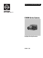
INSTALLATION/OPERATION
C10DN Series Camera
Day/Night, Ultra High Resolution
C2944M-F (1/09)
Contents
List of Tables . . . . . . . . . . . . . . . . . . . . . . . . . . . . . . . . . . . . . . . . . . . . . . . . . . . . . . . . . . . . . . . . . . . . . . . . . . . . . . . . . . . . . . . . . . . . . . . . . . . . . . . . . 3
Important Safety Instructions . . . . . . . . . . . . . . . . . . . . . . . . . . . . . . . . . . . . . . . . . . . . . . . . . . . . . . . . . . . . . . . . . . . . . . . . . . . . . . . . . . . . . . . . . . . . 5
Regulatory Notices . . . . . . . . . . . . . . . . . . . . . . . . . . . . . . . . . . . . . . . . . . . . . . . . . . . . . . . . . . . . . . . . . . . . . . . . . . . . . . . . . . . . . . . . . . . . . . . . . . . . 6
Equipment Handling Precautions . . . . . . . . . . . . . . . . . . . . . . . . . . . . . . . . . . . . . . . . . . . . . . . . . . . . . . . . . . . . . . . . . . . . . . . . . . . . . . . . . . . . . 6
Description. . . . . . . . . . . . . . . . . . . . . . . . . . . . . . . . . . . . . . . . . . . . . . . . . . . . . . . . . . . . . . . . . . . . . . . . . . . . . . . . . . . . . . . . . . . . . . . . . . . . . . . . . . . 7
Models . . . . . . . . . . . . . . . . . . . . . . . . . . . . . . . . . . . . . . . . . . . . . . . . . . . . . . . . . . . . . . . . . . . . . . . . . . . . . . . . . . . . . . . . . . . . . . . . . . . . . . . . . 7
Optional Accessories . . . . . . . . . . . . . . . . . . . . . . . . . . . . . . . . . . . . . . . . . . . . . . . . . . . . . . . . . . . . . . . . . . . . . . . . . . . . . . . . . . . . . . . . . . . . . . 7
Required Tools . . . . . . . . . . . . . . . . . . . . . . . . . . . . . . . . . . . . . . . . . . . . . . . . . . . . . . . . . . . . . . . . . . . . . . . . . . . . . . . . . . . . . . . . . . . . . . . . . . . 7
Camera Layout . . . . . . . . . . . . . . . . . . . . . . . . . . . . . . . . . . . . . . . . . . . . . . . . . . . . . . . . . . . . . . . . . . . . . . . . . . . . . . . . . . . . . . . . . . . . . . . . . . . . . . . . 8
Installation . . . . . . . . . . . . . . . . . . . . . . . . . . . . . . . . . . . . . . . . . . . . . . . . . . . . . . . . . . . . . . . . . . . . . . . . . . . . . . . . . . . . . . . . . . . . . . . . . . . . . . . . . . . 9
Lens Mounting . . . . . . . . . . . . . . . . . . . . . . . . . . . . . . . . . . . . . . . . . . . . . . . . . . . . . . . . . . . . . . . . . . . . . . . . . . . . . . . . . . . . . . . . . . . . . . . . . . . 9
Wiring an Auto Iris Lens . . . . . . . . . . . . . . . . . . . . . . . . . . . . . . . . . . . . . . . . . . . . . . . . . . . . . . . . . . . . . . . . . . . . . . . . . . . . . . . . . . . . . . . 9
Mounting the Lens. . . . . . . . . . . . . . . . . . . . . . . . . . . . . . . . . . . . . . . . . . . . . . . . . . . . . . . . . . . . . . . . . . . . . . . . . . . . . . . . . . . . . . . . . . . . 9
Camera Mounting . . . . . . . . . . . . . . . . . . . . . . . . . . . . . . . . . . . . . . . . . . . . . . . . . . . . . . . . . . . . . . . . . . . . . . . . . . . . . . . . . . . . . . . . . . . . . . . . 10
Connecting Video . . . . . . . . . . . . . . . . . . . . . . . . . . . . . . . . . . . . . . . . . . . . . . . . . . . . . . . . . . . . . . . . . . . . . . . . . . . . . . . . . . . . . . . . . . . . . . . . 10
Connecting Power. . . . . . . . . . . . . . . . . . . . . . . . . . . . . . . . . . . . . . . . . . . . . . . . . . . . . . . . . . . . . . . . . . . . . . . . . . . . . . . . . . . . . . . . . . . . . . . . 11
C10DN-7X Camera Only. . . . . . . . . . . . . . . . . . . . . . . . . . . . . . . . . . . . . . . . . . . . . . . . . . . . . . . . . . . . . . . . . . . . . . . . . . . . . . . . . . . . . . . 11
Connecting AC Power . . . . . . . . . . . . . . . . . . . . . . . . . . . . . . . . . . . . . . . . . . . . . . . . . . . . . . . . . . . . . . . . . . . . . . . . . . . . . . . . . . . . . . . . 12
Connecting DC Power . . . . . . . . . . . . . . . . . . . . . . . . . . . . . . . . . . . . . . . . . . . . . . . . . . . . . . . . . . . . . . . . . . . . . . . . . . . . . . . . . . . . . . . . 13
Connecting Day/Night Filter Control . . . . . . . . . . . . . . . . . . . . . . . . . . . . . . . . . . . . . . . . . . . . . . . . . . . . . . . . . . . . . . . . . . . . . . . . . . . . . 14
Accessing the Setup Menus . . . . . . . . . . . . . . . . . . . . . . . . . . . . . . . . . . . . . . . . . . . . . . . . . . . . . . . . . . . . . . . . . . . . . . . . . . . . . . . . . . . . . . . . . . . . 15
Setup Menus . . . . . . . . . . . . . . . . . . . . . . . . . . . . . . . . . . . . . . . . . . . . . . . . . . . . . . . . . . . . . . . . . . . . . . . . . . . . . . . . . . . . . . . . . . . . . . . . . . . . . . . . 16
Main Menu . . . . . . . . . . . . . . . . . . . . . . . . . . . . . . . . . . . . . . . . . . . . . . . . . . . . . . . . . . . . . . . . . . . . . . . . . . . . . . . . . . . . . . . . . . . . . . . . . . . . . 17
Profiles . . . . . . . . . . . . . . . . . . . . . . . . . . . . . . . . . . . . . . . . . . . . . . . . . . . . . . . . . . . . . . . . . . . . . . . . . . . . . . . . . . . . . . . . . . . . . . . . . . . . . . . . 18
Active . . . . . . . . . . . . . . . . . . . . . . . . . . . . . . . . . . . . . . . . . . . . . . . . . . . . . . . . . . . . . . . . . . . . . . . . . . . . . . . . . . . . . . . . . . . . . . . . . . . . . 18
Exposure Settings . . . . . . . . . . . . . . . . . . . . . . . . . . . . . . . . . . . . . . . . . . . . . . . . . . . . . . . . . . . . . . . . . . . . . . . . . . . . . . . . . . . . . . . . . . . . . . . . 19
Auto Exposure . . . . . . . . . . . . . . . . . . . . . . . . . . . . . . . . . . . . . . . . . . . . . . . . . . . . . . . . . . . . . . . . . . . . . . . . . . . . . . . . . . . . . . . . . . . . . . 19
Eclipser. . . . . . . . . . . . . . . . . . . . . . . . . . . . . . . . . . . . . . . . . . . . . . . . . . . . . . . . . . . . . . . . . . . . . . . . . . . . . . . . . . . . . . . . . . . . . . . . . . . . 19
DC Iris Level . . . . . . . . . . . . . . . . . . . . . . . . . . . . . . . . . . . . . . . . . . . . . . . . . . . . . . . . . . . . . . . . . . . . . . . . . . . . . . . . . . . . . . . . . . . . . . . . 20
Flickerless . . . . . . . . . . . . . . . . . . . . . . . . . . . . . . . . . . . . . . . . . . . . . . . . . . . . . . . . . . . . . . . . . . . . . . . . . . . . . . . . . . . . . . . . . . . . . . . . . 20
Automatic Gain Control . . . . . . . . . . . . . . . . . . . . . . . . . . . . . . . . . . . . . . . . . . . . . . . . . . . . . . . . . . . . . . . . . . . . . . . . . . . . . . . . . . . . . . . 20
Day and Night . . . . . . . . . . . . . . . . . . . . . . . . . . . . . . . . . . . . . . . . . . . . . . . . . . . . . . . . . . . . . . . . . . . . . . . . . . . . . . . . . . . . . . . . . . . . . . 20
Detect Time . . . . . . . . . . . . . . . . . . . . . . . . . . . . . . . . . . . . . . . . . . . . . . . . . . . . . . . . . . . . . . . . . . . . . . . . . . . . . . . . . . . . . . . . . . . . . . . . 21
Filter Limit . . . . . . . . . . . . . . . . . . . . . . . . . . . . . . . . . . . . . . . . . . . . . . . . . . . . . . . . . . . . . . . . . . . . . . . . . . . . . . . . . . . . . . . . . . . . . . . . . 21
Function Settings . . . . . . . . . . . . . . . . . . . . . . . . . . . . . . . . . . . . . . . . . . . . . . . . . . . . . . . . . . . . . . . . . . . . . . . . . . . . . . . . . . . . . . . . . . . . . . . . 21
Line Sync . . . . . . . . . . . . . . . . . . . . . . . . . . . . . . . . . . . . . . . . . . . . . . . . . . . . . . . . . . . . . . . . . . . . . . . . . . . . . . . . . . . . . . . . . . . . . . . . . . 21
White Balance . . . . . . . . . . . . . . . . . . . . . . . . . . . . . . . . . . . . . . . . . . . . . . . . . . . . . . . . . . . . . . . . . . . . . . . . . . . . . . . . . . . . . . . . . . . . . . 22
Chroma. . . . . . . . . . . . . . . . . . . . . . . . . . . . . . . . . . . . . . . . . . . . . . . . . . . . . . . . . . . . . . . . . . . . . . . . . . . . . . . . . . . . . . . . . . . . . . . . . . . . 22
Gamma. . . . . . . . . . . . . . . . . . . . . . . . . . . . . . . . . . . . . . . . . . . . . . . . . . . . . . . . . . . . . . . . . . . . . . . . . . . . . . . . . . . . . . . . . . . . . . . . . . . . 22
Sharpness . . . . . . . . . . . . . . . . . . . . . . . . . . . . . . . . . . . . . . . . . . . . . . . . . . . . . . . . . . . . . . . . . . . . . . . . . . . . . . . . . . . . . . . . . . . . . . . . . 22
Cable Compensation . . . . . . . . . . . . . . . . . . . . . . . . . . . . . . . . . . . . . . . . . . . . . . . . . . . . . . . . . . . . . . . . . . . . . . . . . . . . . . . . . . . . . . . . . 22
Masking . . . . . . . . . . . . . . . . . . . . . . . . . . . . . . . . . . . . . . . . . . . . . . . . . . . . . . . . . . . . . . . . . . . . . . . . . . . . . . . . . . . . . . . . . . . . . . . . . . . 23
Title . . . . . . . . . . . . . . . . . . . . . . . . . . . . . . . . . . . . . . . . . . . . . . . . . . . . . . . . . . . . . . . . . . . . . . . . . . . . . . . . . . . . . . . . . . . . . . . . . . . . . . 23
Save as Custom . . . . . . . . . . . . . . . . . . . . . . . . . . . . . . . . . . . . . . . . . . . . . . . . . . . . . . . . . . . . . . . . . . . . . . . . . . . . . . . . . . . . . . . . . . . . . . . . . 24
Pixel Correction. . . . . . . . . . . . . . . . . . . . . . . . . . . . . . . . . . . . . . . . . . . . . . . . . . . . . . . . . . . . . . . . . . . . . . . . . . . . . . . . . . . . . . . . . . . . . . . . . . 24
System Information. . . . . . . . . . . . . . . . . . . . . . . . . . . . . . . . . . . . . . . . . . . . . . . . . . . . . . . . . . . . . . . . . . . . . . . . . . . . . . . . . . . . . . . . . . . . . . . 24
Lens Focusing. . . . . . . . . . . . . . . . . . . . . . . . . . . . . . . . . . . . . . . . . . . . . . . . . . . . . . . . . . . . . . . . . . . . . . . . . . . . . . . . . . . . . . . . . . . . . . . . . . . . . . . . 25
Camera Synchronization . . . . . . . . . . . . . . . . . . . . . . . . . . . . . . . . . . . . . . . . . . . . . . . . . . . . . . . . . . . . . . . . . . . . . . . . . . . . . . . . . . . . . . . . . . . . . . . 27
Manual White Balance Calibration . . . . . . . . . . . . . . . . . . . . . . . . . . . . . . . . . . . . . . . . . . . . . . . . . . . . . . . . . . . . . . . . . . . . . . . . . . . . . . . . . . . . . . . 28
Specifications . . . . . . . . . . . . . . . . . . . . . . . . . . . . . . . . . . . . . . . . . . . . . . . . . . . . . . . . . . . . . . . . . . . . . . . . . . . . . . . . . . . . . . . . . . . . . . . . . . . . . . . 29
2
C2944M-F (1/09)
List of Illustrations
List of Tables
A
B
C
D
E
1
2
3
4
5
6
7
8
Video Coaxial Cable Requirements . . . . . . . . . . . . . . . . . . . . . . . . . . . . . . . . . . . . . . . . . . . . . . . . . . . . . . . . . . . . . . . . . . . . . . . . . . . . . . . . . . 10
Recommended Wire Gauge and Maximum Wiring Distances. . . . . . . . . . . . . . . . . . . . . . . . . . . . . . . . . . . . . . . . . . . . . . . . . . . . . . . . . . . . . . 11
Day/Night Control Signal . . . . . . . . . . . . . . . . . . . . . . . . . . . . . . . . . . . . . . . . . . . . . . . . . . . . . . . . . . . . . . . . . . . . . . . . . . . . . . . . . . . . . . . . . . 14
Accessing the OSD Menu. . . . . . . . . . . . . . . . . . . . . . . . . . . . . . . . . . . . . . . . . . . . . . . . . . . . . . . . . . . . . . . . . . . . . . . . . . . . . . . . . . . . . . . . . . 15
Settings by Profile. . . . . . . . . . . . . . . . . . . . . . . . . . . . . . . . . . . . . . . . . . . . . . . . . . . . . . . . . . . . . . . . . . . . . . . . . . . . . . . . . . . . . . . . . . . . . . . . 18
C10DN Series Camera . . . . . . . . . . . . . . . . . . . . . . . . . . . . . . . . . . . . . . . . . . . . . . . . . . . . . . . . . . . . . . . . . . . . . . . . . . . . . . . . . . . . . . . . . . . . . 8
DC Drive Auto Iris Lens Connector . . . . . . . . . . . . . . . . . . . . . . . . . . . . . . . . . . . . . . . . . . . . . . . . . . . . . . . . . . . . . . . . . . . . . . . . . . . . . . . . . . . . 9
Mounting Lens to Camera . . . . . . . . . . . . . . . . . . . . . . . . . . . . . . . . . . . . . . . . . . . . . . . . . . . . . . . . . . . . . . . . . . . . . . . . . . . . . . . . . . . . . . . . . . 9
Connecting AC Power . . . . . . . . . . . . . . . . . . . . . . . . . . . . . . . . . . . . . . . . . . . . . . . . . . . . . . . . . . . . . . . . . . . . . . . . . . . . . . . . . . . . . . . . . . . . . 12
Connecting DC Power . . . . . . . . . . . . . . . . . . . . . . . . . . . . . . . . . . . . . . . . . . . . . . . . . . . . . . . . . . . . . . . . . . . . . . . . . . . . . . . . . . . . . . . . . . . . . 13
Day/Night Filter Control Configuration. . . . . . . . . . . . . . . . . . . . . . . . . . . . . . . . . . . . . . . . . . . . . . . . . . . . . . . . . . . . . . . . . . . . . . . . . . . . . . . . 14
Side Panel Button Options . . . . . . . . . . . . . . . . . . . . . . . . . . . . . . . . . . . . . . . . . . . . . . . . . . . . . . . . . . . . . . . . . . . . . . . . . . . . . . . . . . . . . . . . . 15
Lens Focus. . . . . . . . . . . . . . . . . . . . . . . . . . . . . . . . . . . . . . . . . . . . . . . . . . . . . . . . . . . . . . . . . . . . . . . . . . . . . . . . . . . . . . . . . . . . . . . . . . . . . . 25
C2944M-F (1/09)
3
WARNING:
TO PREVENT RISK OF FIRE OR SHOCK, DO NOT EXPOSE THIS CAMERA TO RAIN OR MOISTURE.
PRECAUTION:
DO NOT REMOVE ANY COVER WHILE THE CAMERA IS OPERATING.
PAL: USE ONLY RECOMMENDED POWER SUPPLY, 220 TO 240 VAC, 50 Hz.
CAUTION:
LENS MOUNT OF THE CAMERA IS “CS” MOUNT. CAMERA LENS MOUNT IS SHALLOW, SOME CAMERA
LENSES MAY BOTTOM OUT AND DAMAGE THE CCD IMAGER.
DO NOT TOUCH THE CCD GLASS SURFACE.
THE CAMERA MUST BE INSTALLED NEAR A SOCKET OUTLET, WHICH COULD BE EASILY ACCESSIBLE.
CAUTION
RISK OF ELECTRIC SHOCK
DO NOT OPEN
CAUTION: TO REDUCE THE RISK OF ELECTRIC SHOCK, DO NOT REMOVE COVER
(OR BACK).
NO USER-SERVICEABLE PARTS INSIDE.
REFER SERVICING TO QUALIFIED SERVICE PERSONNEL.
GRAPHIC SYMBOL EXPLANATION
The lighting flash with an arrow-head symbol within an equilateral triangle is intended to
alert the user to the presence of uninsulated “dangerous voltage” within the product's
enclosure, which may be of sufficient magnitude to constitute a risk of electric shock to
persons.
The exclamation point within an equilateral triangle is intended to alert the user to the
presence of important operating and maintenance (servicing) instructions in the literature
accompanying the appliance.
4
C2944M-F (1/09)
Important Safety Instructions
1. Read Instructions. All the safety and operating instructions should be read before the camera is operated.
2. Retain Instructions. The safety and operating instructions should be retained for future reference.
3. Heed Warnings. All warnings on the camera and in the operating instructions should be adhered to.
4. Follow Instructions. All operating and use instructions should be followed.
5. Cleaning: Unplug the power unit from the wall outlet before cleaning. Do not use liquid cleaners or aerosol cleaners. Use a damp cloth for
cleaning.
6. Attachments: Do not use attachments not recommended by your appliance dealer, as they may cause hazards.
7. Water and Moisture: Do not use the camera in any location in which it may be exposed to water or moisture. (For example, dripping,
splashing, or liquid near equipment etc.)
8. Accessories: Do not place the camera on an unstable cart, stand, tripod, bracket, or table. The camera may fall,
causing serious injury to a child or adult, and serious damage to the camera. Use only with mounting accessories
recommended by your appliance dealer or sold with the camera. Any mounting of the camera should follow your
appliance dealer's instructions.
The camera must be installed in a location or on a piece of equipment that can withstand three times the total
weight of the camera, including the lens, camera, mount, adapter, etc.
S3125A
9. Any appliance and cart combination should be moved with care. Quick stops, excessive force, and uneven surfaces may cause the
appliance and cart combination to overturn.
10. Ventilation: The camera should never be placed near or over a radiator or heat register. The camera should not be placed in a built-in
installation such as a bookcase or rack unless proper ventilation is provided or your appliance dealer's instructions have been adhered to.
11. Power Sources: The camera should be operated only from the type of power source indicated on the rating plate. If you are not sure of the
type of power supply for your installation site, consult your appliance dealer or local power company.
12. Power Cord Protection: Power supply cords should be routed so that they are not likely to be walked on or pinched by items placed upon or
against them, paying particular attention to cords at plugs, convenience receptacles, and the point where they exit from the camera.
13. Lightning: For added protection for the camera during a lightning storm, or when it is left unattended and unused for long periods of time,
unplug it from the wall outlet and disconnect the cable system. This will prevent damage to the camera due to lightning and power line surges.
14. Overloading: Do not overload the wall outlet and extension cord, as this can result in a risk of fire or electric shock.
15. Object and Liquid Entry: Never push objects of any kind into the camera through openings, as they may touch dangerous voltage points or
short out parts that could result in a fire or electric shock. Never spill liquid of any kind on the camera.
16. Servicing: Do not attempt to service the camera yourself, as opening or removing covers may expose you to dangerous voltage or other
hazards. Refer all servicing to qualified service personnel.
17. Damage Requiring Service: Unplug the power unit from the wall outlet. Refer servicing to qualified service personnel under the following
conditions.
a. When the power supply cord or plug is damaged.
b.
If liquid has been spilled or objects have fallen into the camera.
c.
If the camera has been exposed to rain or water.
d.
If the camera does not operate normally by following the operating instructions. Adjust only those controls that are covered by the
operating instructions, as an improper adjustment of other controls may result in damage and will often require extensive work by a
qualified technician to restore the camera to its normal operation.
e.
If the camera has been dropped or the cabinet has been damaged.
f.
When the camera exhibits a distinct change in performance. This indicates a need for service.
18. Replacement Parts: When replacement parts are required, be sure the service technician has used replacement parts specified by a
qualified dealer or that have the same characteristics as the original part.
Unauthorized substitutions may result in fire, electric shock, or other hazards.
19. Safety Check: Upon completion of any service or repairs to the camera, ask the service technician to perform safety checks to determine
that the camera is in proper operating condition.
C2944M-F (1/09)
5
Regulatory Notices
This device complies with Part 15 of the FCC Rules. Operation is subject to the following two conditions: (1) this device may not cause harmful
interference, and (2) this device must accept any interference received, including interference that may cause undesired operation.
RADIO AND TELEVISION INTERFERENCE
This equipment has been tested and found to comply with the limits of a Class B digital device, pursuant to Part 15 of the FCC Rules. These limits
are designed to provide reasonable protection against harmful interference in a residential installation. This equipment generates, uses, and can
radiate radio frequency energy and, if not installed and used in accordance with the instructions, may cause harmful interference to radio
communications. However there is no guarantee that the interference will not occur in a particular installation. If this equipment does cause
harmful interference to radio or television reception, which can be determined by turning the equipment off and on, the user is encouraged to try
to correct the interference by one or more of the following measures:
•
Reorient or relocate the receiving antenna.
•
Increase the separation between the equipment and the receiver.
•
Connect the equipment into an outlet on a circuit different from that to which the receiver is connected.
•
Consult the dealer or an experienced radio/TV technician for help.
You may also find helpful the following booklet, prepared by the FCC: “How to Identify and Resolve Radio-TV Interference Problems.” This
booklet is available from the U.S. Government Printing Office, Washington D.C. 20402.
Changes and Modifications not expressly approved by the manufacturer or registrant of this equipment can void your authority to operate this
equipment under Federal Communications Commission’s rules.
This Class B digital apparatus complies with Canadian ICES-003.
Cet appareil numérique de la classe B est conforme à la norme NMB-003 du Canada.
EQUIPMENT HANDLING PRECAUTIONS
To avoid damaging your camera, observe the following precautions:
1. The camera has threaded mounting locations on the top and bottom of the case. Use only a standard photographic mounting bolt with a
1/4-20 UNC thread.
2. Do not touch the surface of the optical filter. If the filter is dusty or is accidentally touched, use clean, compressed air or lens cleaning paper
to clean it.
3. Do not expose the camera imager to direct sunlight as this may impair camera performance. Always keep the lens mount cap in place until
you install the lens.
4. Do not use this camera outdoors without an appropriate enclosure. Do not install near flammable gas or corrosive chemical fumes.
5. Use clean, soft cloths to clean the camera case. If necessary, use a cloth moistened with a neutral detergent diluted with water; then dry
with a dry cloth. Never use alcohol, benzene, or other volatile solutions.
6
C2944M-F (1/09)
Description
The C10DN Series camera is Pelco’s smallest day/night camera. Its day/night technology provides outstanding performance over a wide range of
lighting conditions. The camera also uses a removable infrared (IR) cut filter to switch between color and black-white (B-W) modes as
environmental lighting conditions change.
On-screen programmable menus can be accessed using the side panel controls. Use these menus to customize camera settings for the specific
application.
The C10DN Series camera has a standard CS mount and can be used with fixed, manual, or DC drive auto iris lenses. The auto iris is controlled
through a standard 4-pin square connector that is included with all Pelco auto iris lenses.
The C10DN Series camera is quick and easy to install and is ideal for Pelco’s DomePak® and ImagePak® fixed camera dome/enclosure packages.
MODELS
C10DN-6
1/3-inch high resolution day/night, CCD camera, 24 VAC or 12 VDC, NTSC format
C10DN-6X
1/3-inch high resolution day/night, CCD camera, 24 VAC or 12 VDC, PAL format
C10DN-7X
1/3-inch high resolution day/night, CCD camera, 220–240 VAC, PAL format
OPTIONAL ACCESSORIES
C10-UM
C10 series universal wall/ceiling/rail mounting kit.
LDC100
Auto iris drive converter; converts a DC drive auto iris lens to a video drive auto iris lens. Compatible with all lens size formats.
PCMA40
Lens adapter; adapts standard C-mount lenses to CS-mount cameras.
REQUIRED TOOLS
•
Small Phillips screwdriver for connector cover
•
Small flat tip screwdriver for serial termination
•
Allen wrench (1.5 mm) for back focus adjustment
•
Neutral density filter (ND3) for auto iris adjustment
C2944M-F (1/09)
7
Camera Layout
C10DN-7X BACK
Figure 1. C10DN Series Camera
ì Camera Mount: Use the top or bottom mount hole. The maximum thread depth is 0.25 inches (6.4 mm); refer to Camera Mounting on
page 10.
î Back Focus Locking Screw: Use a 1.5-mm Allen wrench to adjust the back focus (refer to Lens Focusing on page 25). Back focus is set
at the factory for a standard CS-mount back focus distance.
ï Lens Mount: Mount a standard CS-mount lens to the C10DN Series camera (refer to Lens Mounting on page 9). To use a C-mount lens,
install a C- or CS-mount adapter.
ñ Auto Iris Lens Connector: Insert the 4-pin connector from the DC drive auto iris lens into this connector (refer to Lens Mounting on
page 9).
ó Setup Button: Use this five-position button to configure the camera through the setup menus (refer to Accessing the Setup Menus on
page 15).
r Ground Screw: Use this screw terminal as a ground.
s Power Connector (refer to Connecting Power on page 11):
•
•
C10DN-6/6X, Terminal Block: Use the 2-pin terminal block to connect either 12 VDC or 24 VAC power.
C10DN-7X, Power Cord: A 2-terminal type cord for 220–240 VAC.
t Video Output Connector: Connect a coaxial video cable to this BNC connector to output the video image (refer to Connecting Video on
page 10).
8
C2944M-F (1/09)
Installation
LENS MOUNTING
The C10DN Series camera supports both manual and auto iris lenses, either fixed focal length or varifocal. It also supports both DC and video
drive lenses. It automatically senses an auto iris lens as soon as you plug in the connector. The camera has a standard CS mount that can accept
a C-mount lens with a PCMA40 lens adapter.
After mounting a DC drive auto iris lens, but before using the camera, perform the dc drive auto iris automatic adjustment procedure (refer to
DC Iris Level on page 20). Also perform this procedure each time you change the lens.
WIRING AN AUTO IRIS LENS
Auto iris lenses are controlled through the 4-pin drive connector (type D4-152N). Figure 2 identifies the pin connections for the auto iris lens
connector on the side of the camera.
LENS CONNECTOR
Pin
1
2
3
4
DC Drive
Control coil negative (–)
Control coil positive (+)
Drive coil positive (+)
Drive coil negative (–)
Video Drive
+9 VDC (40 mA maximum)
+9 VDC (40 mA maximum)
AI-Video
GND
Figure 2. DC Drive Auto Iris Lens Connector
MOUNTING THE LENS
To mount the lens onto the camera refer to Figure 3, and then complete the following steps:
1. Make sure the lens will not touch the camera imager when installed.
2. Use clean, compressed air or a clean, dry lens cloth to make sure there is no dust or other foreign matter between the lens and the camera
imager.
3. C-mount lens: Screw the adapter onto the lens.
4. Screw the lens onto the lens mount.
CS-MOUNT LENS
C/CS-MOUNT ADAPTER
(FOR C-MOUNT LENS ONLY)
AUTO IRIS LENS CABLE
AND CONNECTOR (OPTIONAL)
Figure 3. Mounting Lens to Camera
5. Auto iris lens: Connect the 4-pin connector from the lens to the connector on the side of the camera.
6. Perform the lens focusing procedure before using the lens (refer to Lens Focusing on page 25).
C2944M-F (1/09)
9
CAMERA MOUNTING
The C10DN Series camera can be mounted from either the top or bottom, depending on the type of camera mount used in your installation. Use a
standard 1/4-20 screw. The maximum thread depth (top) is 0.188 inches (4.7 mm). To extend the thread depth (top) to 0.25 inches (6.4 mm), use
the camera mount spacer (supplied). The maximum thread depth (bottom) is 0.25 inches (6.4 mm).
The C10DN Series camera can be fitted with most Pelco lenses and mounted into most Pelco domes and enclosures, resulting in the greatest
possible number of combinations. This means you can find a solution for nearly any application.
When selecting a lens, dome, or enclosure for this camera, consider how the physical dimensions of each component may affect camera
installation and operation.
NOTE: To simplify lens and enclosure selection, Pelco offers ImagePak options for the C10DN Series camera. Select the lens and the dome or
enclosure. Pelco will build and test it for you. Contact Pelco or your dealer for more information.
CONNECTING VIDEO
Connect a coaxial video cable to the BNC connector on the back of the camera. Refer to Table A for the type of video coaxial cable to use.
Table A. Video Coaxial Cable Requirements
Cable Type*
Maximum Distance
RG59/U
750 ft (229 m)
RG6/U
1,000 ft (305 m)
RG11/U
1,500 ft (457 m)
*Cable requirements:
75-ohm impedance
All-copper center conductor; steel-center
conductor cable may result in poor performance
All-copper braided shield with 95% braid coverage
If white spots appear in the video image, one or more pixels on the camera imager may be defective. This condition is common to CCD camera
imagers. To correct this condition, refer to Save as Custom on page 24.
10
C2944M-F (1/09)
CONNECTING POWER
The C10DN-6 and C10DN-6X are designed to operate from either a 12 VDC or a 24 VAC power source. The camera automatically senses power type.
Use only a Class 2 isolated power source that can supply 12 VDC ±15% or 24 VAC ±15%, 50/60 Hz. Maximum power consumption is about 3.5 W.
WARNINGS:
•
Do not connect high voltage power to the camera because you may damage the camera.
•
Do not short circuit the power leads when connecting the power supply to the camera.
•
Do not remove the connector cover during camera operation.
NOTES:
•
Be sure to use 60 Hz power for NTSC (C10DN-6) and 50 Hz power for PAL (C10DN-6X and C10DN-7X).
•
Install the camera near a socket or outlet that is easily accessible.
Use Table B to help you identify the necessary wire gauge and maximum cable distance. This table applies to 2-conductor solid copper wire.
(Reduce distance by 10 percent for stranded copper wire.) These maximum distances are based on a maximum allowable voltage drop of
10 percent.
Table B. Recommended Wire Gauge and Maximum Wiring Distances
Maximum Distance
Wire Gauge
24 AWG (0.25 mm2)
22 AWG (0.35 mm2)
20 AWG (0.5 mm2)
18 AWG (1.0 mm2)
16 AWG (1.5 mm2)
14 AWG (2.5 mm2)
12 AWG (4.0 mm2)
10 AWG (6.0 mm2)
12 VDC
80 ft (24 m)
128 ft (39 m)
203 ft (61 m)
323 ft (98 m)
514 ft (156 m)
816 ft (248 m)
1,295 ft (394 m)
2,057 ft (626 m)
24 VAC
323 ft (98 m)
513 ft (156 m)
815 ft (248 m)
1,295 ft (394 m)
2,056 ft (626 m)
3,264 ft (994 m)
5,183 ft (1,579 m)
8,228 ft (2,507 m)
C10DN-7X CAMERA ONLY
The C10DN-7X camera uses a power main supply of 220–240 VAC, 50 Hz. This main supply must also have a minimum rating of 50 mA.
CAUTION: Unplug the power cord during installation.
C2944M-F (1/09)
11
CONNECTING AC POWER
The C10DN Series camera requires a power supply of 24 VAC ±15% 20.4–27.6 VAC, 50/60Hz. Make sure the power supply has a minimum rating
of 270 mA.
When connecting more than one camera to the same AC transformer, remember the following information:
•
Connect the same side of the transformer to the same terminal on all cameras; otherwise, the cameras may be out of phase, causing a
vertical roll when switching between cameras (refer to Camera Synchronization on page 29 for more information).
•
Use a transformer whose rated power supply has a minimum of 270 mA multiplied by the number of cameras.
To connect AC power, refer to Figure 4 and complete the following steps:
1. Strip at least 0.4 inches (10 mm) of the insulation from both power wires.
2. Connect both power wires to the terminal block that is supplied with the camera.
3. Plug the terminal block into the 2-pin connector on the back of the camera and tighten the screw.
4. If you are also using a ground wire, connect it to the screw marked GND.
POWER SUPPLY
INPUT
24 VAC
OUTPUT
Figure 4. Connecting AC Power
12
C2944M-F (1/09)
CONNECTING DC POWER
The C10DN Series camera requires a power supply of 12 VDC ±15% 10.2–13.8 VDC. Make sure the power supply has a minimum rating of
390 mA.
WARNINGS:
•
For safety, include a 1.0 A slow blow fuse when connecting DC power, as shown in Figure 5.
•
The DC power supply must be UL and CE certified.
•
Make sure you wire the power polarity correctly.
To connect DC power refer to Figure 5, and then complete the following steps:
1. Strip at least 0.4 inches (10 mm) of the insulation from both power wires.
2. Connect the negative wire from the power supply to the indicated hole in the terminal block that is supplied with the camera.
3. Connect the positive wire from the power supply to the indicated hole in the terminal block.
4. Plug the terminal block into the 2-pin connector on the back of the camera and tighten the screw.
5. For safety, add a 1.0 A slow blow fuse to the positive wire from the power supply. The fuse should be less than 4 inches (10 cm) from the
positive terminal on the power supply.
4 INCHES (10 CM) MAXIMUM
POWER
SUPPLY
INPUT
+12 VDC
GND
Figure 5. Connecting DC Power
C2944M-F (1/09)
13
CONNECTING DAY/NIGHT FILTER CONTROL
In some installations, high infrared (IR) illumination or other light sources may interfere with the camera’s automatic day/night mode operation.
Use an external day/night filter switch, such as a photosensor, to keep the camera from constantly switching filters.
The control signal input responds as shown in Table C.
Table C. Day/Night Control Signal
Signal
Open or High
Short or Low
Voltage
3.0 V to 3.3 V
-0.3 V to 0.3 V
Day/Night Mode
AUTO
B-W
NOTES:
•
Do not exceed the values listed in Table C.
•
The C10DN Series camera responds only to the input signal from the switch. It does not provide enough power to drive an external device.
To connect an external day/night filter switch to the camera, refer to Figure 6, and then complete the following steps:
1. Turn off power to the camera.
2. If necessary, use a small Phillips screwdriver to remove the connector cover from the rear panel (refer to Figure 6).
3. If necessary, plug the external control connector assembly (supplied) into the camera. Then use a small Phillips screwdriver to secure the
assembly cover to the rear panel.
4. Use 100-ohm twisted pair cable to wire the device to the enclosed connector assembly. The decision to use shielded cable depends on your
installation; shielded cable may be optional.
D&N CONTROL
SIGNAL INPUT
PIN 7
PIN 1
GND (6)
Figure 6. Day/Night Filter Control Configuration
5. Wire the camera to the external switch as follows:
• Pin 7 (brown, signal input) to the (+) positive lead on the external switch.
•
Pin 6 (black, ground) to the (–) negative lead on the external switch.
•
Shielded cable only: Connect the shield to either pin 3 (black, ground) or pin 6 (black, ground).
6. Change DAY & NIGHT to EXT. (external) on the EXPOSURE SETTINGS menu.
7. Configure the external switch as follows:
• Open or High: Camera operates in AUTO mode.
•
14
Short or Low: Camera operates in B-W mode.
C2944M-F (1/09)
Accessing the Setup Menus
Use the five-position button controller on the side panel of the camera to access and navigate the on-screen display (OSD) menus (refer to
Figure 7 and Table D).
LEFT
UP
SELECT
RIGHT
DOWN
Figure 7. Side Panel Button Options
Table D. Accessing the OSD Menu
Menu Options
Display the MAIN MENU on the screen.
Move the cursor up or down in a menu; or toggle through menu selections.
Move the cursor right or left in a menu.
Select menu or make a menu selection.
Save a setting and then return to the menu.
Navigating the Menu
Press and hold down the center button for two seconds.
Move the button up or down.
Move the button left or right.
Press the center button.
Press the center button.
To display a menu, complete the following steps:
1. Press and hold the center button for two seconds to open the MAIN MENU.
2. Press the button up or down to select a menu.
3. Press the center of the button to open the menu.
To change a setting, complete the following steps:
1. Press the button up or down to select the item.
2. Press the center of the button to open the item.
3. Press the button up or down to toggle through the menu selections.
4. Press the center of the button to save the setting and return to the menu.
To move to a previous menu, select BACK and press the center of the button. To close the setup menus, select EXIT from any menu and press the
center of the button.
NOTES:
•
When you select BACK or EXIT on any menu, the camera saves the current settings.
•
The menu closes automatically after three minutes of inactivity.
C2944M-F (1/09)
15
Setup Menus
The C10DN Series camera uses setup menus instead of hardware switches for configuring the camera. As a result, you have more options for
customizing the camera for its specific application.
NOTE: After you customize any aspect of the C10DN Series camera, be sure to save your custom settings. (Refer to Profiles on page 18 for
information about saving custom settings.)
PROFILES
STANDARD
GAMING
CUSTOM
BACK
MAIN MENU
PROFILES
EXPOSURE SET.
FUNCTION SET.
SAVE AS CUSTOM
PIXEL CORRECTION
SYSTEM INFORMATION
->
->
->
->
->
->
EXIT
EXPOSURE SET.
EXIT
AUTO EXPOSURE
ECLIPSER
DC IRIS LEVEL
FLICKERLESS
AGC
BACK
ECLIPSER
-> ESC
-> OFF
-> -8
-> OFF
-> LOW
ECLIPSER
THRESHOLD
LEVEL
BACK
-> OFF
-> 17
-> 4
EXIT
EXIT
LINE SYNC
LINE SYNC
V-PHASE ADJ
BACK
EXIT
FUNCTION SET.
LINE SYNC
WHITE BALANCE
CHROMA
GAMMA
SHARPNESS
CABLE COMPENSATION
MASKING
TITLE
BACK
-> AUTO
-> 38
CHROMA
-> AUTO
-> AUTO
->
-> 60%
-> SHARP
-> SHORT
->
->
CHROMA GAIN
RED HUE
BLUE HUE
BACK
-> 0
-> -2
-> 0
EXIT
MASK SETTING
MASKING
EXIT
MASK
MASK COLOR
MASK EDIT
MASK ERASE
SAVE AS CUSTOM
BACK
-> OFF
-> -2
-> 0
SELECT START POSITION
NOW POINT = ( XXX, XXX )
EXIT
CURRENT SETTING
ARE SAVED
OK
CANCEL
TITLE EDIT
TITLE
TITLE
EDIT TITLE
PIXEL CORRECTION
BACK
-> OFF
EXIT
COVER THE LENS
AND PRESS OK
OK
BS
RETURN
CANCEL
SYSTEM INFORMATION
FIRMWARE VERSION
OSD VERSION
RESTORE FACTORY SETTINGS ->
BACK
16
ABCDEFGHIJKLM
NOPQRSTUVWXYZ
abcdefghijklm
nopqrstuvwxyz
123456789-/
RESTORE FACTORY SETTING
#.##
#.##
ALL SETTING ARE
INITIALIZED
OK
CANCEL
EXIT
C2944M-F (1/09)
MAIN MENU
The following sections describe each menu and the settings associated with that menu. The sample
screens in each section show the default settings.
To display the MAIN MENU, complete the following steps:
1. Press and hold the center button on the side of the camera (refer to Accessing the Setup Menus
on page 15).
MAIN MENU
PROFILES
EXPOSURE SET.
FUNCTION SET.
SAVE AS CUSTOM
PIXEL CORRECTION
SYSTEM INFORMATION
->
->
->
->
->
->
EXIT
2. Use the Pelco controller to navigate through the menus.
Profiles
Select this option to access the camera profile settings (refer to Profiles on page 18).
Exposure Set.
Select this option to configure the exposure settings (refer to Exposure Settings on page 19).
Function Set.
Select this option to configure the function settings (refer to Function Settings on page 21).
Save as Custom
Select this option to configure and save a custom profile (refer to Pixel Correction on page 24).
Pixel Correction
Select this option to perform the automatic pixel correction procedure (refer to Save as Custom on page 24).
System Information
Select this option to display the camera firmware information or to restore the factory default settings (refer to System Information on page 24).
C2944M-F (1/09)
17
PROFILES
Use this option to select a profile or save custom settings. Use profiles for faster installation or to
adjust camera settings quickly for changing light conditions. The default setting is DAY&NIGHT.
The C10DN Series camera offers three predefined profiles and one custom, or user-definable, profile.
You cannot modify predefined profiles.
PROFILES
STANDARD
GAMING
CUSTOM
BACK
EXIT
ACTIVE
Select one of the following application profiles:
STANDARD:
Select this profile for most scenes.
DAY&NIGHT: Select this profile if the camera is located outside a building or in certain indoor low light applications (this is the default
setting). When selected, the camera adjusts its settings to account for light level changes. For example, parking lots and
walkways.
GAMING:
Select this profile if the camera scene is illuminated by mixed interior lighting and includes self-illuminated devices.
For example, an arcade with gaming machines that have bright, flashing lights.
CUSTOM:
Select this profile to activate your saved custom settings (refer to Save as Custom on page 24).
Table E shows the default camera settings for each profile. Figure 8 shows sample scenes for each camera profile.
Table E. Settings by Profile
Profile
AUTO EXPOSURE
ECLIPSER
DC IRIS LEVEL
FLICKERLERSS
AGC
DAY & NIGHT
DETECT TIME
FILTER LIMIT
STANDARD
DAY&NIGHT (default)
Exposure Settings
ESC
ESC
OFF
OFF
-8
-8
OFF
OFF
LOW
LOW
COLOR
AUTO
—
5 SEC
—
10 MIN
GAMING
ESC
OFF
-8
OFF
LOW
COLOR
—
—
Function Settings
LINE SYNC
WHITE BALANCE
CHROMA
GAMMA
SHARPNESS
CABLE COMPENSATION
MASKING
TITLE
18
AUTO
AUTO
—
60%
SHARP
SHORT
—
—
AUTO
AUTO
—
60%
SHARP
SHORT
—
—
INT
INDOOR
—
60%
SHARP
SHORT
—
—
C2944M-F (1/09)
EXPOSURE SETTINGS
EXPOSURE SET.
Select this option to configure the exposure settings for the C10DN Series camera.
AUTO EXPOSURE
The automatic exposure feature automatically adjusts the electronic shutter and mechanical iris to set
the correct exposure. Default settings depend on the selected profile (refer to Table E on page 18.)
Select one of the following automatic exposure modes:
AUTO EXPOSURE
ECLIPSER
DC IRIS LEVEL
FLICKERLESS
AGC
BACK
-> ESC
-> OFF
-> -8
-> OFF
-> LOW
EXIT
ESC:
Select this mode for optimal brightness level by increasing the number of stored fields.
NORMAL:
Select this mode to use the electronic shutter and manual iris to control exposure. As
lighting conditions change, the camera adjusts exposure based on input from the electronic shutter.
BLC:
Select this mode for scenes that are strongly backlit. The camera corrects the image to bring out the detail of the subject, such
as a person entering a building through a door.
BLC + ESC:
Select this mode to make objects in the center of the scene brighter. ESC adjusts the shutter speed according to the incident
light levels.
ECLIPSER
The eclipser feature adjusts a foreground image to compensate for a very bright background. With a
normal auto iris lens, when a bright backlight overcomes a dim foreground subject, the iris may not
compensate for the scene properly. As a result, details in the image are lost.
Use this feature in parking garages, parking lots, driveways, and other entrances with a variety of
bright light sources.
ECLIPSER
ECLIPSER
THRESHOLD
LEVEL
BACK
-> OFF
-> 17
-> 4
EXIT
NOTE: The Auto Exposure setting must be set to NORMAL to use the eclipser feature.
ECLIPSER:
Select ON or OFF to enable or disable the eclipser function. When set to ON, the THRESHOLD and LEVEL settings can be
changed. The default setting is OFF.
THRESHOLD: The threshold value identifies an adjustment for the foreground brightness. The range is 0 (zero) to 25. The default setting is 17.
LEVEL:
The level value identifies an adjustment level for the lens to ignore the background. The range is 1 (light gray) to 8 (black);
the default setting is 4.
To activate this setting, complete the following steps:
1. Set AGC to OFF.
2. Set AUTO EXPOSURE to NORMAL.
3. Set ECLIPSER to OFF.
4. Set the video output level to one of the following lens options:
• Video type lens: Set the response selector of the auto iris lens to AVERAGE. Set the video output level of the camera to 0.75 Vp-p by
adjusting the LEVEL VR of the auto iris len.
• DC type lens: Set the video output level of the camera to 0.75 Vp-p by adjusting the DC IRIS LEVEL.
5. If the object in the foreground is dark (unrecognizable) and the background is predominant, set ECLIPSER to ON, and then set LEVEL to 4 or 5.
6. Adjust the THRESHOLD until the object in the foreground can be seen.
C2944M-F (1/09)
19
DC IRIS LEVEL
Select this option to adjust the electronic properties of the DC drive auto iris lens to the auto iris electronic properties of the camera. Perform this
procedure before using the camera or each time you change the lens.
To perform this procedure, complete the following steps:
1. Focus the camera (refer to Lens Focusing on page 25).
2. Aim the camera at a bright, flickerless scene.
3. Select DC IRIS LEVEL from the MAIN MENU.
4. Adjust the DC IRIS LEVEL value (for the best image). The range is -20 to 20; the default setting is -8.
5. Press the center of the button to save the value.
6. Exit the MAIN MENU.
FLICKERLESS
In some installations, the cycle of the fluorescent lights may interfere with the electronic iris shutter speed. Use this option to override the
shutter speed. When enabled, the shutter speed is set to 1/100 (NTSC) or 1/120 (PAL).
Select ON or OFF. The default setting is OFF.
NOTE: This option appears when AUTO EXPOSURE is set to NORMAL or BLC.
AUTOMATIC GAIN CONTROL
Automatic gain control (AGC) automatically adjusts the image when the light level changes. Most scenes benefit from AGC operation.
Select LOW, HIGH, or OFF. The default setting is LOW.
DAY AND NIGHT
This feature specifies how the camera will switch between day (color) and night (B-W) operation.
Select one of the following day and night options:
AUTO:
Switches the filter automatically as light conditions change. The D&N DETECTION and D&N FILTER LIMIT settings appear.
The camera switches from day to night when the AGC gain level reaches 22 dB. It switches from night to day when the AGC gain
level reaches 16 dB.
When AUTO is selected, both the angle of view and the lighting conditions may cause the camera filters to switch constantly.
COLOR:
Operates the camera in day mode.
BW:
Operates the camera in night mode.
EXT:
Enables an external signal to switch between day and night modes (refer to Connecting Day/Night Filter Control on page 14 for
more information). The D&N DETECTION and D&N FILTER LIMIT become enabled. In some installations, this option may be more
reliable than AUTO mode.
NOTE: When AGC is disabled, AUTO is not available; you can select only COLOR or B-W mode.
20
C2944M-F (1/09)
DETECT TIME
The camera regularly checks the brightness level. When the brightness level crosses the switch threshold and lasts longer than the
D&N DETECTION setting, the camera switches the filter.
For example, the headlights of a passing car affect the brightness level in the camera, but not long enough for the filter to switch. The constant
light from a cloudy day also affects the brightness level in the camera, long enough for the filter to switch.
Select one of the following options: 5 SEC, 30 SEC. The default setting is 5 SEC.
NOTE: This option is only enabled when the DAY&NIGHT option is set to AUTO.
FILTER LIMIT
In certain lighting conditions, the brightness level may cross the switch threshold quickly. As a result, the camera may constantly switch filters.
Use this option to indicate how often to test the brightness level.
Select one of the following detection test intervals:
OFF:
Select this option to test the brightness level continuously, according to the D&N DETECTION setting (5 seconds or 30 seconds).
10 MIN:
Select this option to test the brightness level every 10 minutes.
30 MIN:
Select this option to test the brightness level every 30 minutes.
The default setting is 10 MIN when the DAY&NIGHT profile is selected. Otherwise, the default setting is OFF.
After the camera switches filters three times, and after the filter limit interval has passed, an asterisk (*) appears next to this setting.
This indicates that the detection test has been performed.
NOTE: This option is only enabled when the DAY&NIGHT option is set to AUTO.
FUNCTION SETTINGS
Select this option to configure the function settings for the C10DN Series camera.
LINE SYNC
Use line synchronization to eliminate the vertical roll that occurs when multiple cameras are connected
to the same switching device. Line synchronization locks each camera to the same frame rate.
FUNCTION SET.
LINE SYNC
WHITE BALANCE
CHROMA
GAMMA
SHARPNESS
CABLE COMPENSATION
MASKING
TITLE
BACK
-> AUTO
-> AUTO
->
-> 60%
-> SHARP
-> SHORT
->
->
EXIT
Line Sync
Select one of the following line sync options:
LINE SYNC
AUTO:
INT:
When using AC power, select this option to operate in line lock mode. This mode
synchronizes the frame rate to the power phase. When selected, you can also
manually set the vertical phase for this camera (refer to V-Phase Adjustment below
and to Camera Synchronization on page 27 for more information).
LINE SYNC
V-PHASE ADJ
BACK
-> AUTO
-> 38
EXIT
Select this option to use the internal sync generator.
The default setting is AUTO, except for the GAMING profile, whose default is INT.
NOTES:
•
When using DC power, the camera always uses the internal synchronization generator.
•
When you select INT, the V-PHASE ADJ option is disabled.
V-Phase Adjustment
Use this menu to adjust the vertical phase for line synchronization. The range is 0 (zero) to 52 for NTSC cameras and 0 (zero) to 62 for PAL
cameras.
Press the button up or down to adjust vertical phase. When correct, press the center of the button to return to the LINE SYNC menu.
C2944M-F (1/09)
21
WHITE BALANCE
The C10DN Series camera offers three white balance options. White balance settings define how the camera processes video images to render
true colors in a scene. White balance is especially effective in scenes with changing color temperatures. Use it also in installations with
incandescent, fluorescent, or outdoor lighting.
Select one of the following white balance modes:
AUTO:
In this mode, the camera automatically adjusts the white balance based on the colors in the camera scene. The camera
continually delivers the best possible image.
HOLD:
Use this mode to calibrate the camera to the white balance in a neutral scene. This prevents dominant colors in the target scene
from affecting white balance (refer to Manual White Balance Calibration on page 28 for more information).
INDOOR:
Use this mode for indoor scenes. The white balance gain is set to approximately 2,800°K and does not change as the scene
colors change.
CHROMA
Select this option to display the MANUAL RED/BLUE menu.
CHROMA
CHROMA:
Use this option to increase or decrease the light level in the camera image. Select a
value between -1 and 1; the default setting is 0 (zero).
RED HUE:
Use this option to either increase or decrease the red hue in the camera image. Select
a value between -5 and 5; the default setting is -2.
BLUE HUE:
Use this option to either increase or decrease the blue hue in the camera image. Select a value between -5 and 5; the default
setting is 0 (zero).
CHROMA GAIN
RED HUE
BLUE HUE
BACK
-> 0
-> -2
-> 0
EXIT
GAMMA
Gamma correction adjusts the video signal to compensate for the nonlinear response of the monitor display. Select one of the following options:
60%(NORM) or 100%. The default setting depends on the selected profile (refer to Table E on page 18).
SHARPNESS
Sharpness enhances picture detail by increasing the aperture gain of the camera and sharpening the edges in the picture. Available settings
include SOFT A, SOFT B, and SHARP. The default setting is SHARP.
CABLE COMPENSATION
Cable compensation mode adjusts the signal output in proportion to the length of the cable. Available settings include SHORT, MIDDLE, and
LONG. The default setting is SHORT.
22
SHORT:
Use this option for cable lengths up to 328 ft (100 m).
MIDDLE:
Use this option for cable lengths from 328 to 984 ft (100 to 300 m).
LONG:
Use this option for cable lengths from 984 to 1640 ft (300 to 500 m).
C2944M-F (1/09)
MASKING
MASKING
Masking lets you block certain areas of a camera scene. A maximum of eight masks can be defined.
NOTE: If you add a ninth mask, the camera erases the first mask. You cannot configure more than
eight masks.
MASK
MASK COLOR
MASK EDIT
MASK ERASE
BACK
MASK:
-> OFF
-> -2
-> 0
EXIT
Use this option to enable or disable masking; the default setting is OFF.
MASK COLOR: Use this option to select the color of the mask. Available settings are black, white,
gray, red, green, blue, and yellow. The default setting is BLACK.
MASK EDIT:
Use this option to edit one mask. To edit a mask, complete the following steps:
1. Change the MASK setting on the MASKING menu to ON.
MASKTITLE
SETTING
SELECT
TITLE START POSITION
EDIT TITLE
BACK
-> OFF
EXIT
NOW POINT = ( XXX, XXX )
2. Select the MASK EDIT menu. The MASK SETTING menu appears.
3. Use the pointer to configure the mask area.
a. Press the button up, down, left, or right to move the cursor to the upper-left corner of the mask.
b.
Press the center of the button to mark the upper-left corner.
c.
Press the button up, down, left, or right to move the cursor to the lower-right corner of
the mask. If you move the cursor either left or above the start point, the mask edit is
cancelled.
d.
Press the center of the button to mark the lower-right corner. The mask area is blacked out. The MASKING menu appears with the
new mask.
4. Repeat step 3 for each additional mask.
Mask Erase
Select this option to erase one or more masks. The camera erases masks from the last created to the first created. To erase a mask, select MASK
ERASE. The mask that was last created disappears. Repeat to erase additional masks.
TITLE
Select this option to configure the camera title.
TITLE:
Use this option to enable or disable the title display; the default setting is OFF.
EDIT TITLE:
Use this option to enter or edit the camera title, up to 16 characters. The default
setting is blank.
TITLE
TITLE
EDIT TITLE
BACK
-> OFF
EXIT
To enter a camera title, complete the following steps:
1. Change the TITLE setting on the TITLE menu to ON.
2. Select the EDIT TITLE menu. The EDIT TITLE menu appears.
3. Press the button up, down, left, or right to move the cursor to the desired character.
The space character is located below the letter “n.”
4. Press the center of the button to select the character. The selected character appears in the
blank area at the bottom of the screen.
TITLE EDIT
ABCDEFGHIJKLM
NOPQRSTUVWXYZ
abcdefghijklm
nopqrstuvwxyz
123456789-/
BS
RETURN
5. To clear a character, select BS (backspace). The camera deletes the last character entered.
6. Repeat steps 3 and 4 until you have entered the camera title.
7. When the title is correct, select BACK to return to the TITLE menu.
C2944M-F (1/09)
23
SAVE AS CUSTOM
Select this option to create and save a custom profile. Whenever you open and make changes to the
EXPOSURE SET and FUNCTION SET menus, the camera stores the settings. These setting can be saved
as a custom profile.
SAVE AS CUSTOM
CURRENT SETTING
ARE SAVED
OK
CANCEL
To save defined exposure and function settings as a CUSTOM profile, complete the following steps:
1. Move the cursor to the SAVE AS CUSTOM menu.
2. Press the menu selection button, the SAVE AS CUSTOM menu is displayed.
3. Move the cursor to OK and then press the selection button again. The profile is saved and the screen automatically returns to the MAIN
MENU.
PIXEL CORRECTION
If white spots appear in the video image, one or more pixels on the camera imager may be defective.
This condition is common to CCD camera imagers.
Select this option to automatically detect and correct these defects. This feature helps you maintain
image quality.
PIXEL CORRECTION
COVER THE LENS
AND PRESS OK
OK
CANCEL
To perform this procedure, complete the following steps:
1. Use a lens cap to cover the lens. Make sure no light can enter the lens. The mechanical iris lens aperture does not completely block the
light. Therefore, you should use a lens cap.
2. Select PIXEL CORRECTION. The PIXEL CORRECTION menu appears.
3. Select OK. The camera performs the procedure and the MAIN MENU appears.
NOTE: Any defective pixels that cannot be completely corrected may still appear.
SYSTEM INFORMATION
Select this option to display the camera firmware information.
Restore Factory Settings
Select this option to reset the camera to the factory default settings. This option clears all saved userdefinable settings, except the following:
•
CAMERA SETUP menu: ADDRESS, COM SPEED
•
LINE SYNC menu: V-PHASE ADJ
•
PIXEL CORRECTION
RESTORE FACTORY SETTING
ALL SETTING ARE
INITIALIZED
OK
CANCEL
To restore the camera to the factory default settings, complete the following steps:
1. Select RESTORE FACTORY SETTINGS on the SYSTEM INFORMATION menu. The RESTORE FACTORY SETTINGS menu appears.
2. Select OK. The camera resets all parameters to the factory default settings (except those listed above), and then the MAIN MENU appears.
24
C2944M-F (1/09)
Lens Focusing
After mounting the lens, you must focus your C10DN Series camera. You will adjust both the back focus (on the camera) and the fine focus (on
the lens).
NOTE: The back focus has already been adjusted using a standard CS-mount lens. However, you might need to adjust it again to match the
mounted lens.
1. Auto iris only: Cover the auto iris lens with a suitable neutral density (ND) filter; this opens the iris fully. For best results, use an ND3 filter.
2. Manual iris only: Open the iris completely. Figure 8 shows the manual iris, varifocal, and lens focus locking screws for a sample lens.
Refer to your lens documentation for more information.
BACK FOCUS
LOCKING SCREW
VARIFOCAL
LOCKING SCREW
LENS FOCUS
LOCKING SCREW
1.5 MM ALLEN WRENCH
MANUAL IRIS
LOCKING SCREW
Figure 8. Lens Focus
3. If Automatic Gain Control (AGC) is set to OFF, set it to LOW or HIGH on the FUNCTION SETTINGS menu. AGC is set to LOW by default.
a. Display the FUNCTION SETTINGS menu.
b.
Change AGC to either LOW or HIGH.
c.
Select EXIT to save the AGC setting.
4. Aim the camera at the farthest object in the field of view. Make sure it is at least 6.5 ft (2 m) away.
5. Fixed focal length lens only:
a.
Set the lens focal length to far (∞).
b.
Adjust the back focus.
c.
Use a 1.5-mm Allen wrench to loosen the back focus locking screw.
d.
Turn the lens until the image is focused. Tighten the back focus locking screw clockwise.
WARNING: Do not overtighten the back focus locking screw because you may damage the camera.
(Back focus is a coarse adjustment. You will make the fine focus adjustment in the next step.)
e.
C2944M-F (1/09)
Adjust the lens focus to achieve the best fine focus.
25
6. Varifocal lens only:
a.
b.
Set the varifocal to wide (W) and the lens focal length to far (∞).
Adjust the back focus:
(1) Use a 1.5-mm Allen wrench to loosen the back focus locking screw.
(2)
Turn the lens until the image is focused.
(3)
Tighten the back focus locking screw clockwise.
WARNING: Do not overtighten the back focus locking screw because you may damage the camera.
(Back focus is a coarse adjustment. You will make the fine focus adjustment in steps c and d.)
c.
Move the varifocal locking screw up or down to set the field of view.
d.
Adjust the lens focus to achieve the best fine focus.
e.
Repeat steps c and d until the focus is correct.
7. Manual iris only: Adjust the iris for the best picture quality. The largest aperture gives the best light sensitivity; the smallest aperture
gives the greatest depth of field.
8. Tighten all lens locking screws.
WARNING: When tightening the lens locking screws, do not overtighten or force any screw.
9. Auto iris only: Remove the ND filter.
10. If necessary, reset the AGC setting to its previous value.
a. Display the FUNCTION SETTINGS menu.
b.
Change AGC to OFF, LOW, or HIGH.
c.
Select EXIT to save the AGC setting.
11. Auto iris only: Perform the auto iris lens adjustment procedure (refer to DC Iris Level on page 20).
26
C2944M-F (1/09)
Camera Synchronization
Camera synchronization may affect installations that use two or more AC power supplies for multiple cameras. Due to different power phases,
a brief vertical roll may appear on the monitor when switching between cameras. To eliminate this vertical roll, adjust the phase control to
synchronize the cameras to one another.
It may be necessary for two people to communicate when synchronizing cameras, one at the camera and the other at the monitor, to observe the
vertical roll and the effect of any camera adjustments.
To synchronize cameras, complete the following steps:
1. Choose a reference camera to which all other cameras will be phased.
2. Access V-PHASE ADJ menu for a camera. Press the button up and down to adjust the vertical phase until the camera is synchronized to the
reference camera.
A dual trace oscilloscope is recommended, but not required, to adjust camera phase. Align the vertical sync pulses of the reference camera
to the selected camera.
3. After making each adjustment, switch back and forth between the adjusted camera and the reference camera. Repeat this process until the
roll between the cameras disappears completely.
4. Adjust the phase of all other cameras by repeating steps 2 and 3. Always adjust to the reference camera selected in step 1.
5. As soon as you finish customizing this and all other camera settings, save your custom settings into the CUSTOM profile. This protects
them if the camera loses power or if it must be restarted (refer to Profiles on page 18 for more information).
To adjust phase control:
1. Select LINE SYNC on the FUNCTION SETTINGS menu. The LINE SYNC menu appears.
2. Switch the LINE SYNC setting to AUTO.
3. Select V-PHASE ADJ. The V-PHASE ADJ menu appears.
4. Press the button up or down to change the PHASE VALUE. On the C10DN-6 (NTSC) camera, the range is 0 (zero) to 52. On the C10DN-6X
(PAL) camera, the range is 0 (zero) to 62.
5. Press the center of the button to return to the LINE SYNC menu.
6. Select EXIT to close the setup menus.
7. As soon as you finish customizing this and all other camera settings, save your custom settings into the CUSTOM profile. This protects
them if the camera loses power or if it must be restarted (refer to Profiles on page 18 for more information).
C2944M-F (1/09)
27
Manual White Balance Calibration
In some installations, use manual white balance to render the most accurate image color possible. Mixed color applications may affect the
amount of color adjustment. For example, a small white object on a large blue surface may have a reddish tint. The HOLD white balance setting
uses a calibration image to identify the correct white level. The camera then uses this white level when adjusting overall image color.
NOTE: The HOLD white balance setting is recommended only for indoor applications that have a single primary light source.
For example a C10DN camera is installed in a pan/tilt enclosure inside a clothing store, in a shopping mall. A variety of colors are located
throughout the store. Overhead lights provide the primary illumination, but some light also enters the store from the mall. As the camera pans a
section filled with blue clothing, the camera may redden the image to compensate for the blue. When properly calibrated, the camera will not try
to adjust scenes with predominant amounts of red or blue.
To calibrate the manual white balance, complete the following steps:
1. Focus the camera on a neutral color scene. Select a neutral scene with the following characteristics:
•
Little or no black
•
Not predominantly red
•
Not predominantly blue
•
No direct light source, such as a lamp or a window
2. Select WHITE BALANCE on the FUNCTION SETTINGS menu.
3. Select AUTO. This calibrates the white balance gain to the neutral scene.
4. Change WHITE BALANCE from AUTO to HOLD. This locks the white balance gain
into camera memory.
NOTE: If you change WHITE BALANCE from HOLD to a different mode, the stored manual white balance settings are erased. You will have
to perform this procedure again.
5. Select EXIT to close the setup menus.
6. Focus the camera on the target scene.
7. As soon as you finish customizing this and all other camera settings, save your custom settings into the CUSTOM profile. This protects
them if the camera loses power or if it must be restarted (refer to Profiles on page 18 for more information).
28
C2944M-F (1/09)
Specifications
GENERAL
Day/Night Operation
Day
Night
Infrared (IR) cut filter
BK-7 glass, same optical displacement as day
Imaging Device
1/3-inch interline transfer CCD
Picture Elements
NTSC
PAL
768 (H) x 494 (V) (approx. 380 k)
752 (H) x 582 (V) (approx. 440 k)
Sensing Area
3/16 x 1/8-inch (4.7 x 3.5 mm)
Scanning System
NTSC
PAL
525 lines, 2:1 interlace
625 lines, 2:1 interlace
Synchronization
AC line lock/internal
Horizontal Resolution
540 TV lines
Electronic Shutter Range
NTSC
PAL
1/60-1/100,000 second
1/50-1/100,000 second
Auto Iris Lens Type
DC drive (autosensing)
Sensitivity
Color
B-W
0.4 lux, f/1.2, 50 IRE, AGC on, 89% scene reflectance
0.08 lux, f/1.2, 50 IRE, AGC on, 89% scene reflectance
Minimum Illumination
Color
B-W
0.3 lux, f/1.2, 40 IRE, AGC on, 75% scene reflectance
0.07 lux, f/1.2, 40 IRE, AGC on, 75% scene reflectance
Signal-to-Noise Ratio
>50 dB
Vertical Phase
Adjustable ±90°
Automatic Gain Control
Selectable: on/off
Backlight Compensation
Selectable: on/off
Flickerless Mode
Selectable: on/off; 1/100 sec (NTSC),
1/120 sec (PAL)
Auto White Balance
Selectable: on/off, 4 modes
Day/Night
Selectable: on/off, 4 modes
Signal Processing
Digital signal processing (DSP)
Video Output
1 Vp-p, 75 ohms
Gamma Correction
Selectable: on/off, 0.6, 1.0
White Balance Range
2,500° to 9,500°K
ELECTRICAL
Power Requirements
C10DN-6
C10DN-6X
C10DN-7X
24 VAC ±15%/12 VDC ±15%, 60 Hz
24 VAC ±15%/12 VDC ±15%, 50 Hz
220–240 VAC, 50 Hz
Power Consumption
3W
Power Connector
2-pin terminal strip, push-in type
Video Connector
BNC
Auto Iris Connector
4-pin connector (miniature square)
Controls
5-position button
MECHANICAL
Lens Mount
CS mount
Camera Mount
1/4-inch UNC-20 screw, top or bottom of camera housing
C2944M-F (1/09)
29
ENVIRONMENTAL
Operating Temperature
14° to 122°F (-10° to 50°C)
Storage Temperature
-4° to 140°F (-20° to 60°C)
Operating Humidity
20% to 80% (noncondensing)
Storage Humidity
20% to 90% (noncondensing)
PHYSICAL
Dimensions
C10DN-6/C10DN-6X
C10DN-7X
2.95" L x 2.17" W x 1.97" H
(7.5 x 5.5 x 5.0 cm)
5.50" L x 2.17" W x 1.97" H
(13.97 x 5.5 x 5.0 cm)
Weight (without lens)
C10DN-6/C10DN-6X
C10DN-7X
0.44 lb (0.20 kg)
0.88 lb (0.40 kg)
Shipping Weight
C10DN-6/C10DN-6X
C10DN-7X
1 lb (0.45 kg)
2 lb (0.90 kg)
(Design and product specifications subject to change without notice.)
30
C2944M-F (1/09)
PRODUCT WARRANTY AND RETURN INFORMATION
WARRANTY
Pelco will repair or replace, without charge, any merchandise proved defective in
material or workmanship for a period of one year after the date of shipment.
Exceptions to this warranty are as noted below:
• Five years:
– Fiber optic products
– TW3000 Series unshielded twisted pair (UTP) transmission products
– CC3701H-2, CC3701H-2X, CC3751H-2, CC3651H-2X, MC3651H-2, and
MC3651H-2X camera models
• Three years:
– Pelco-branded fixed camera models (CCC1390H Series, C10DN Series,
C10CH Series, IP3701H Series, and IX Series)
– EH1500 Series enclosures
– Spectra® IV products (including Spectra IV IP)
– Camclosure® Series (IS, ICS, IP) integrated camera systems
– DX Series digital video recorders, DVR5100 Series digital video recorders,
Digital Sentry ® Series hardware products, DVX Series digital video
recorders, and NVR300 Series network video recorders
– Endura® Series distributed network-based video products
– Genex® Series products (multiplexers, server, and keyboard)
– PMCL200/300/400 Series LCD monitors
• Two years:
– Standard varifocal, fixed focal, and motorized zoom lenses
– DF5/DF8 Series fixed dome products
– Legacy® Series integrated positioning systems
– Spectra III™, Spectra Mini, Spectra Mini IP, Esprit®, ExSite®, and PS20
scanners, including when used in continuous motion applications.
– Esprit Ti and TI2500 Series thermal imaging products
– Esprit and WW5700 Series window wiper (excluding wiper blades).
– CM6700/CM6800/CM9700 Series matrix
– Digital Light Processing (DLP®) displays (except lamp and color wheel). The
lamp and color wheel will be covered for a period of 90 days. The air filter is
not covered under warranty.
– Intelli-M® eIDC controllers
• One year:
– Video cassette recorders (VCRs), except video heads. Video heads will be
covered for a period of six months.
• Six months:
– All pan and tilts, scanners, or preset lenses used in continuous motion
applications (preset scan, tour, and auto scan modes).
Pelco will warrant all replacement parts and repairs for 90 days from the date of
Pelco shipment. All goods requiring warranty repair shall be sent freight prepaid
to a Pelco designated location. Repairs made necessary by reason of misuse,
alteration, normal wear, or accident are not covered under this warranty.
Pelco assumes no risk and shall be subject to no liability for damages or loss
resulting from the specific use or application made of the Products. Pelco’s liability
for any claim, whether based on breach of contract, negligence, infringement of
any rights of any party or product liability, relating to the Products shall not exceed
the price paid by the Dealer to Pelco for such Products. In no event will Pelco be
liable for any special, incidental, or consequential damages (including loss of use,
loss of profit, and claims of third parties) however caused, whether by the
negligence of Pelco or otherwise.
The above warranty provides the Dealer with specific legal rights. The Dealer may
also have additional rights, which are subject to variation from state to state.
If a warranty repair is required, the Dealer must contact Pelco at (800) 289-9100 or
(559) 292-1981 to obtain a Repair Authorization number (RA), and provide the
following information:
1. Model and serial number
2. Date of shipment, P.O. number, sales order number, or Pelco invoice number
3. Details of the defect or problem
If there is a dispute regarding the warranty of a product that does not fall under
the warranty conditions stated above, please include a written explanation with
the product when returned.
Method of return shipment shall be the same or equal to the method by which the
item was received by Pelco.
RETURNS
To expedite parts returned for repair or credit, please call Pelco at (800) 289-9100
or (559) 292-1981 to obtain an authorization number (CA number if returned for
credit, and RA number if returned for repair) and designated return location.
All merchandise returned for credit may be subject to a 20 percent restocking and
refurbishing charge.
Goods returned for repair or credit should be clearly identified with the assigned
CA or RA number and freight should be prepaid.
12-23-08
The materials used in the manufacture of this document and its components are compliant to the requirements of Directive 2002/95/EC.
This equipment contains electrical or electronic components that must be recycled properly to comply with Directive 2002/96/EC of the European Union
regarding the disposal of waste electrical and electronic equipment (WEEE). Contact your local dealer for procedures for recycling this equipment.
REVISION HISTORY
Manual #
C2944M
C2944M-A
C2944M-B
C2944M-C
C2944M-D
C2944M-E
C2944M-F
Date
11/07
1/08
3/08
4/08
6/08
10/08
1/09
Comments
Original version.
Revised Figure 6 and made changes to setup menus.
Corrected electronic shutter range specification.
Added Important Safeguards, safety instructions, and power connection information for model C10DN-7X.
Revised power requirements for model C10DN-7X.
Revised instructions for camera setup.
Revised instructions for camera setup. Updated signal-to-noise ratio specification.
Pelco, the Pelco logo, Camclosure, DomePak, Digital Sentry, Endura, Esprit, ExSite, Genex, ImagePak, Intelli-M, Legacy, and Spectra are registered trademarks of Pelco, Inc.
Spectra III is a trademark of Pelco, Inc.
DLP is a registered trademark of Texas Instruments Incorporated.
© Copyright 2009, Pelco, Inc. All rights reserved.
www.pelco.com
Pelco, Inc. Worldwide Headquarters 3500 Pelco Way Clovis, California 93612 USA
USA & Canada Tel (800) 289-9100 Fax (800) 289-9150
International Tel +1 (559) 292-1981 Fax +1 (559) 348-1120