1
= Vertical bar in left or right margin indicates change or addition.
®
BK4000/BK4024/BK4220 Series
Blower Kit
Installation/Operation
Manual C436M-B (12/94)
1.0 WARNINGS
2.0 SCOPE
Prior to installation and use of this product, the following
WARNINGS should be observed.
The information contained within this manual covers
the installation and operation of the BK4000/BK4024/
BK4220 Blower Kits. Please familiarize yourself with
the information in this manual prior to installation and
operation.
1.
Installation and servicing should only be done by
Qualified Service Personnel and conform to all
Local codes.
2.
Unless the unit is specifically marked as a NEMA
Type 3-6P enclosure, it is designed for Indoor use
only and it must not be installed where exposed to
rain and moisture.
2.1 DESCRIPTION
4.
Only use replacement parts recommended by
PELCO.
The BK4000/BK4024/BK4220 Blower Kits are engineered for installation in the EH4014 and EH4018 Enclosures. The BK4000 requires 120 VAC, the BK4024
requires 24 VAC, and the BK4220 requires 230 VAC.
All units can be used in conjunction with the corresponding Heater Kit.
BK4000 requires 4 watts at 120 VAC, 60 Hz.
BK4024 requires 3 watts at 24 VAC, 60 Hz. (CE)
BK4220 requires 4.8 watts at 230 VAC, 60Hz. (CE)
NOTE: Once installed, the blower kit will reduce
the maximum camera/lens length specified by 13/4 inches.
PELCO • 300 W. Pontiac Way, Clovis, CA 93612-5699 • USA • (800) 289-9100 or (1-559) 292-1981
FAX (800) 289-9150 or (1-559) 292-3827 • DataFAX (800) 289-9108 or (1-559) 292-0435
3.0 INSTALLATION
1.
Remove the Phillips Head screws from the rear cap
and slide the assembly out from the enclosure.
The BK4000/BK4024/BK4220 Blower Kits are supplied with the following installation parts:
2.
Attach the blower assembly to the rear plate using
two of the self-tapping screws, holding the end
cap to the sled.
3.
Wire according to the wiring diagram in Figure 2.
QTY
ITEM
1
1
Blower
Blower Bracket
To install the BK4000/BK4024/BK4220 perform the
following steps (refer to Figure 1):
NOTE: When used with a heater kit (and
PCB), the blower can be wired into the terminal block on the PC Board (see Figure 2). With
the blower kit only, the PCB is not necessary.
3.1 PARTS LIST (Figure 1.)
Item
Qty
1
2
1
1
1
1
1
1
1
1
4
4
2
2
2
8
3
4
5
A
B
C
D
E
F
Description
Part Number
Bracket, fan/pc board
Bracket component, 24VAC, 230VAC
PCB assy, term/thermott, (used with heater kit)
Fan, 2.36-inch Sq., 120/230 VAC
Fan, 2.36-inch Sq., 24VDC
Resistor 3k ohm, 10w (230 VAC blowerkit only)
Diode Bridge Rect, 1A400PRV (24 VAC only)
Insulator, PC board (heater kit only)
Washer, nylon
Screw, 6-32 x 3/8 pan phil SS
Screw, 6-32 x 1.5 pan phil SS
Nut, hex, 6-32
Screw, 6-32 x 1/4 self tapping phil
Internal tooth lockwasher, #6
BK40004000COMP
BK7044002COMP
PCB9000300ASSY
MM750010003
ED210005
RES003.0K10.0
DIOMDA104
BK400010000
ZH200X437X62N
ZH6-32X.375SPP
ZH6-32X1.50SPP
ZH6-323NUTSH
ZH6-SFX.250SPP
ZH6LWSIS
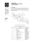
Figure 1. Blower Kit Installation
2
PELCO Manual C436M-B (12/94)
4.0 WIRING DIAGRAMS
The following items are supplied in the blower kits.
Refer to Figure 2 for wiring information with the use
of the heater kit PCB board, and without.
Quantity
Item
1
1
1
1
1
1
PELCO Part No.
Fan, 120 VAC, 19 CFM
Fan, 24 VDC, 19 CFM
Resistor for fan, 3K ohm
Bridge Rectifier Diode
Capacitor
Component Bracket
Thermostat
MM750010003
ED210005
RES003.0K10.0
DIOMDA104
CAPU0050.0/25
BK7044002COMP
Input, AC High
Input, AC (neutral)
Ground
1
2
3
4
5
6
7
8
9
10
Blower Kit
Input, AC High
Input, AC (neutral)
Ground
1
2
3
4
5
6
7
8
9
10
Fan
Heater
Cap
Fan
Diode
Bridge
Heater
120 VAC Model
24 VAC Model
1
2
3
4
5
6
7
8
9
10
Heater/Blower wiring
diagrams using
Heater Kit with PCB.
120 & 230 VAC models
24 VAC model
230 VAC model
24 VAC model
24 VAC model
24 & 230 VAC models
Input, AC High
Input, AC (neutral)
Ground
Fan
Resistor
Heater
Heater
230 VAC Model
Butt Splices Provided
Diode Bridge
Fan
Fan
Cap
120 VAC (BK4000)
Blower Wiring
Installation only.
PCB not required.
+
_
AC
24 VAC (BK4024)
Resistor
Fan
230 VAC (BK4220)
Figure 2. Blower Kit Wiring Diagram
PELCO Manual C436M-B (12/94)
3
5.0 WARRANTY AND RETURN
INFORMATION
WARRANTY
RETURNS
PELCO will repair or replace, without charge, any
merchandise proved defective in material or
workmanship for a period of one year after the date of
shipment (six months on all pan and tilts with auto scan
and medium duty scanners, and two years on Legacy®,
Intercept® and CM9500/CM8500 Matrix products).
PELCO will warranty all replacement parts and repairs
for 90 days from the date of shipment. All goods for
warranty work shall be sent freight prepaid to our
Clovis, California facility. Repairs made necessary by
reason of misuse, alteration, normal wear, or accident
are not covered under this warranty. PELCO is not
liable for any incidental or consequential expenses or
liability incurred by the customer as a result of field
repair, installation, or any other reason.
In order to expedite parts returned to the factory for
repair or credit, please call the factory at (800) 2899100 or (559) 292-1981 to obtain an authorization
number (CA number if returned for credit, and RA
number if returned for repair). Goods returned for
repair or credit should be clearly identified with the
assigned CA/RA number and freight should be prepaid.
All merchandise returned for credit may be subject to
a 20% restocking and refurbishing charge.
Ship freight prepaid to:
PELCO
300 West Pontiac Way
Clovis, CA 93612-5699
The above warranty is in lieu of any other expressed or
implied warranty, condition, or guarantee by PELCO
of the equipment listed herein. PELCO makes no
warranties except for intended use and will not be liable
for any loss, damage, or costs arising, whether
consequential or incidental, from the use of said
merchandise.
This warranty gives you specific legal rights. You may
also have additional rights, which are subject to variation
from state to state.
If a warranty repair is required, contact PELCO at
(800) 289-9100 or (559) 292-1981 for a
Repair Authorization number (RA), and provide the
following information:
1.
2.
3.
Model and serial number
Date of shipment, P.O. number, Sales Order
number, or PELCO invoice number
Details of the defect or problem
If there is a dispute regarding the warranty of a product
which does not fall under the warranty conditions
stated above, please include a written explanation with
the product when returned.
Ship freight prepaid to:
®
PELCO
300 West Pontiac Way, Clovis, CA 93612-5699
(559) 292-1981 • (800) 289-9100
FAX (800) 289-9150 or (559) 292-3827 •
DataFAX (800) 289-9108 or (559) 292-0435
International customers call 1-559-292-1981 or
FAX 1-559-348-1120
(Product specifications subject to change
without notice.)
C436M-B
PELCO
300 West Pontiac Way
Clovis, CA 93612-5699
Method of return shipment shall be the same as method
by which the repair item is received by PELCO.
4
PELCO Manual C436M-B (12/94)