1
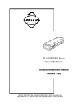
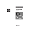
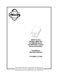
EH3500 Series
Environmental
Enclosure
Maintenance/Service
Manual
C478SM (8/99)
Pelco • 300 W. Pontiac Way, Clovis • CA 93612-5699 USA • Pelco Online @ http://www.pelco.com
In North America and Canada: Tel (800) 289-9100 or FAX (800) 289-9150 • DataFAX (800) 289-9108
International Customers: Tel (1-559) 292-1981 or FAX (1-559) 348-1120 • DataFAX (1-559) 292-0435
CONTENTS
Section
Page
IMPORTANT SAFEGUARDS AND WARNINGS ................................................................ 3
DESCRIPTION ................................................................................................................... 3
MODELS .................................................................................................................... 3
EH3500 SERIES ................................................................................................ 3
EH3515L LEGACY® SERIES ............................................................................. 4
MAINTENANCE ................................................................................................................. 5
EXPLODED ASSEMBLY AND WIRING DIAGRAMS ......................................................... 5
EH3500 SERIES ENCLOSURE ................................................................................. 5
ACCESSORIES FOR THE EH3508/EH3512/EH3515 SERIES ................................ 7
EH3515L LEGACY® SERIES ENCLOSURE ............................................................. 12
ACCESSORIES FOR THE EH3515L LEGACY® SERIES ........................................ 13
WARRANTY AND RETURN INFORMATION ....................................................................16
LIST OF ILLUSTRATIONS
Figure
1
2
3
4
5
6
7
8
Page
EH3500 Series Enclosure Exploded Assembly Diagram ................................... 5
EH3508/EH3512/EH3515 Series Accessories Exploded Assembly Diagram .... 7
EH3508/EH3512/EH3515 Series Wiring Diagram ............................................ 11
EH3515L Legacy® Series Exploded Assembly Diagram .................................. 12
EH3515L Legacy® Series Accessories Exploded Assembly Diagram ............... 13
EH3515L Legacy® Series Wiring Diagram ........................................................ 15
EH3515L Legacy® Series Circuit Board Component Locations ........................ 16
EH3515L Legacy® Series Layout of Circuit Board Traces ................................ 16
LIST OF TABLES
Table
A
B
C
D
E
F
2
Page
EH3500 Series Enclosure Exploded Assembly Parts List ................................. 6
EH3508 Series Accessories Exploded Assembly Parts List .............................. 8
EH3512 Series Accessories Exploded Assembly Parts List .............................. 9
EH3515 Series Accessories Exploded Assembly Parts List ............................. 10
EH3515L Legacy® Series Exploded Assembly Parts List ................................. 12
EH3515L Legacy® Series Accessories Exploded Assembly Parts List ............. 14
Pelco Manual C478SM (8/99)
IMPORTANT SAFEGUARDS AND WARNINGS
Prior to installation and use of this product, the following warnings should be observed.
1.
Installation and servicing should only be done by qualified service personnel and
conform to all local codes.
2.
Unless the unit is specifically marked as a NEMA Type 3, 3R, 3S, 4, 4X, 6, or 6P
enclosure, it is designed for indoor use only and it must not be installed where
exposed to rain and moisture.
3.
Only use replacement parts recommended by Pelco.
4.
After replacement/repair of this unit’s electrical components, conduct a resistance
measurement between line and exposed parts to verify the exposed parts have not
been connected to line circuitry.
5.
The installation method and materials should be capable of supporting four times the
weight of the enclosure, pan/tilt, camera and lens combination.
The product and/or manual may bear the following marks:
This symbol indicates that
dangerous voltage constituting a
risk of electric shock is present
within this unit.
This symbol indicates that there
are important operating and
maintenance instructions in the
literature accompanying this unit.
CAUTION:
RISK OF ELECTRIC SHOCK.
DO NOT OPEN.
Please thoroughly familiarize yourself with the information in this manual prior to installation
and operation.
DESCRIPTION
The EH3508/EH3512/EH3515 Series are indoor/outdoor light-duty camera enclosures
designed for use with various cameras on the market and accommodate fixed focal length
lenses or motorized zoom lenses, with or without auto-iris operation.
The lid of the enclosure is hinged in the front providing easy access during installation and
when camera/lens adjustments are necessary. The camera sled itself serves as an
elevation block. You can remove, flip, and then reinstall the sled to elevate the camera. All
wiring and cabling is brought into the enclosure through adjustable gland at the bottom rear
of the enclosure.
The rear link-lock latch can be used with a padlock of suitable size for applications requiring
additional security.
The EH3515L Legacy® Series enclosures are used with pan/tilt units in Pelco’s PT480
Series. The enclosures are mounted on the bottom. A connector in the pan/tilt unit attaches
the enclosure, mechanically and electrically, to the pan/tilt unit.
MODELS
EH3500 SERIES
Pelco Manual C478SM (8/99)
EH3508
Enclosure, indoor/outdoor, 8.75-inch (22.23 cm) lower body length. (CE)
EH3508-1
EH3508 with 120 VAC defroster and thermostatically controlled heater;
13 watts
EH3508-2
EH3508 with 24 VAC defroster and thermostatically controlled heater;
13 watts
3
EH3508-3
EH3508 with 230 VAC defroster and thermostatically controlled heater;
13 watts
EH3512
Enclosure, indoor/outdoor, 12.75-inch (32.38 cm) lower body length.
(CE)
EH3512-1
EH3512 with 120 VAC defroster, blower, and thermostatically
controlled heater; 17 watts
EH3512-1HD
EH3512 with 120 VAC defroster and thermostatically controlled heater;
13 watts
EH3512-2
EH3512 with 24 VAC defroster, blower, and thermostatically controlled
heater; 15 watts
EH3512-2HD
EH3512 with 24 VAC defroster and thermostatically controlled heater;
13 watts
EH3512-3
EH3512 with 230 VAC defroster, blower, and thermostatically
controlled heater; 22 watts
EH3512-3HD
EH3512 with 230 VAC defroster and thermostatically controlled heater;
13 watts
EH3515
Enclosure, indoor/outdoor, 15.75-inch (40.00 cm) lower body length.
(CE)
EH3515-1
EH3515 with 120 VAC defroster, blower, and thermostatically
controlled heaters; 27 watts
EH3515-1HD
EH3515 with 120 VAC defroster and thermostatically controlled
heaters; 23 watts
EH3515-2
EH3515 with 24 VAC defroster, blower, and thermostatically controlled
heaters; 25 watts
EH3515-2HD
EH3515 with 24 VAC defroster and thermostatically controlled heaters;
23 watts
EH3515-3
EH3515 with 230 VAC defroster, blower, and thermostatically
controlled heaters; 32 watts
EH3515-3HD
EH3515 with 230 VAC defroster and thermostatically controlled
heaters; 23 watts
EH3515L LEGACY® SERIES
4
EH3515L
Enclosure, indoor/outdoor, 15.75-inch (40.00 cm) lower body length.
(CE)
EH3515L-1
EH3515 with 120 VAC defroster, blower, and thermostatically
controlled heaters; 27 watts (CE)
EH3515L-1HD
EH3515 with 120 VAC defroster and thermostatically controlled
heaters; 23 watts
EH3515L-2
EH3515 with 24 VAC defroster, blower, and thermostatically controlled
heaters; 25 watts (CE)
EH3515L-2HD
EH3515 with 24 VAC defroster and thermostatically controlled heaters;
23 watts
EH3515L-3
EH3515 with 230 VAC defroster, blower, and thermostatically
controlled heaters; 32 watts (CE)
EH3515L-3HD
EH3515 with 230 VAC defroster and thermostatically controlled
heaters; 23 watts
Pelco Manual C478SM (8/99)
MAINTENANCE
Regularly scheduled maintenance prolongs the operational life and appearance of the
equipment. Clean the window regularly with a soft cloth using a mild, nonabrasive
detergent and water to maintain picture clarity.
EXPLODED ASSEMBLY AND WIRING DIAGRAMS
EH3500 SERIES ENCLOSURE
G
Figure 1. EH3500 Series Enclosure Exploded Assembly Diagram
Pelco Manual C478SM (8/99)
5
Table A. EH3500 Series Enclosure Exploded Assembly Parts List
Item
1
2
3
4
Qty
1
2
2
1
5
6
7
8
27 in.
36 in.
42 in.
1
1
1
9
10*
11
12
13
1
2
1
2
1
A
B*
C
D*
E
F
2
4
2
4
2
2
G
H
4
4
Description
Lid attachment pin
Type E clip
Gland
Body
8-inch enclosure
12-inch enclosure
15-inch enclosure
Bulb seal gasket
8-inch enclosure
12-inch enclosure
15-inch enclosure
Link latch lock
Camera sled
8-inch enclosure
12-inch and 15-inch enclosure
Lid with latch
8-inch enclosure
12-inch enclosure
15-inch enclosure
Lid bracket hinge
Window bracket
Window and gasket
Gland nut
Lid spring
Rivet
Flat washer
Screw, 6-32 x 3/8-inch, Phillips, pan head
Screw, 6-32 x 3/8-inch, Phillips, type F
Screw, 4-40 x 3/8-inch, Phillips, pan head
Nylon washer
8-inch enclosure
12-inch and 15-inch enclosure
Nut, 4-40, hex
Internal tooth lock washer, #4
Part Number
EH350010105
ZH.125ECLIP
EH470010007B
37004001ASSY
37004000ASSY
35154000ASSY
EH470010011
EH550010010
EH35064236COMP
EH35004256COMP
EH35084135COMP
EH35004235COMP
35154003COMP
EH35004141COMP
EH35004142COMP
EH35001000ASSY
EH470010008B
EH350010107
ZHRVT1/8X3/8CE
ZH148X375X32C
ZH6-32X.375SPP
ZH6-SFX.375SPP
ZH4-40X.375SPP
ZH200X437X62N
ZH131X361X62N
ZH4-40NUTSH
ZH4LWSIS
* Applies only to EH3508, EH3512, and EH3515.
6
Pelco Manual C478SM (8/99)
ACCESSORIES FOR THE EH3508/EH3512/EH3515 SERIES
19
14
(3)
(3)
M
N
18
(1)
(2)
19
21
19
J
(2)
20
20
I
18
L
14
20
20
J
17
17
K
(1) USED ONLY ON MODELS
EH3515-1/-2/-3,
EH3515-1HD/-2HD/-3HD,
(2) USED ONLY ON MODELS
EH3512-1/-2/-3,
EH3515-1/-2/-3
(3) USED ONLY ON MODELS
EH3515-1HD/-2HD/-3HD
Figure 2. EH3508/EH3512/EH3515 Series Accessories Exploded Assembly Diagram
Pelco Manual C478SM (8/99)
7
Table B. EH3508 Series Accessories Exploded Assembly Parts List
Item
I
J
Qty
1
1
1
1
K
L
14
15
16
17
18
19
20
1
1
1
1
4
Description
Part Number
Heater bracket
Heater, thermostatically controlled
120 VAC
24 VAC
230 VAC
Defroster, continuous-duty
120 VAC
24 VAC
230 VAC
PC board
9484024
HT21-0201-0100
HT02-1022-4310
HT23-0201-0100
HT21-1201-0100
HT02-0322-4306
HT23-1201-0100
PCB9100301ASSY
ZH6-SFX.375SPP
4
2
1
8
Screw, 6-32 x 3/8-inch, Phillips, type F, pan head
Not used
Not used
Pop rivet, 3/8-inch
Screw, 6-32 x 3/8-inch, Phillips, type F, pan head
Internal tooth lock washer, #6
Nylon washer
1
24 VAC rectifier
PCB9000277ASSY
ZHRVT1/8X3/8CE
ZH6-SFX.375SPP
ZH6LWSIS
ZH131X361X62N
24 VAC Model Only
*
* Illustrated in 24 VAC wiring diagram in Figure 3.
8
Pelco Manual C478SM (8/99)
Table C. EH3512 Series Accessories Exploded Assembly Parts List
Item
I
J
Qty
1
1
1
1
K
L
N
1
1
1
1
1
1
1
14
15
16
17
18
19
20
21
4
4
2
5
3
8
2
Description
Heater bracket
Heater, thermostatically controlled
120 VAC
24 VAC
230 VAC
Defroster, continuous-duty
120 VAC
24 VAC
230 VAC
PC board
Blower
120 VAC
24 VDC
230 VAC*
Part Number
9484024
HT21-0201-0100
HT02-1022-4310
HT23-0201-0100
HT21-1201-0100
HT02-0322-4306
HT23-1201-0100
PCB9100301ASSY
MM750010003
ED210005
MM750010003
Screw, 6-32 x 3/8-inch, Phillips, type F, pan head
Not used
Not used
Pop rivet, 3/8-inch
Screw, 6-32 x 3/8-inch, Phillips, type F, pan head
Internal tooth lock washer, #6
EH3512-1/-2/-3
EH3512-1HD/-2HD/-3HD
Nylon washer
Screw
EH3512-1/-3: 6-32 x 1 1/2-inch,
Phillips, pan head
EH3512-2: 6-32 x 1 3/8-inch,
Phillips, pan head
ZH6-SFX.375SPP
24 VDC rectifier board
PCB9000277ASSY
ZHRVT1/8X3/8CE
ZH6-SFX.375SPP
ZH6LWSIS
ZH131X361X62N
ZH6-32X1.50SPS
ZH6-32X1.375SPP
24 VAC Models Only
**
1
* Uses 120 VAC blower and resistor (resistor not included)
** Illustrated in 24 VAC wiring diagram in Figure 3.
Pelco Manual C478SM (8/99)
9
Table D. EH3515 Series Accessories Exploded Assembly Parts List
Item
I
J
Qty
1
2
2
2
K
L
M
N
1
1
1
1
1
1
1
1
14
4
6
15
16
17
18
19
20
21
6
4
4
8
2
Description
Part Number
Heater bracket
Heater, thermostatically controlled
120 VAC
24 VAC
230 VAC
Defroster, continuous-duty
120 VAC
24 VAC
230 VAC
PC board
Rear heater bracket
Blower
120 VAC
24 VDC
230 VAC*
9484024
HT21-0201-0100
HT02-1022-4310
HT23-0201-0100
HT21-1201-0100
HT02-0322-4306
HT23-1201-0100
PCB9100301ASSY
MF01-0030-004A
MM750010003
ED210005
MM750010003
Screw, 6-32 x 3/8-inch, Phillips, type F, pan head
EH3515-1/-2/-3
EH3515-1HD/-2HD/-3HD
Not used
Not used
Pop rivet, 3/8-inch
Screw, 6-32 x 3/8-inch, Phillips, type F, pan head
Internal tooth lock washer, #6
Nylon washer
Screw
EH3515-1/-3: 6-32 x 1 1/2-inch,
Phillips, pan head
EH3515-2: 6-32 x 1 3/8-inch,
Phillips, pan head
ZH6-SFX.375SPP
24 VDC rectifier board
PCB9000277ASSY
ZHRVT1/8X3/8CE
ZH6-SFX.375SPP
ZH6LWSIS
ZH131X361X62N
ZH6-32X1.50SPS
ZH6-32X1.375SPP
24 VAC Models Only
**
1
* Uses 120 VAC blower and resistor (resistor not included)
** Illustrated in 24 VAC wiring diagram in Figure 3.
10
Pelco Manual C478SM (8/99)
120 VAC MODEL
DEFROSTER
INPUT, AC HIGH
INPUT, AC LOW (NEUTRAL)
GROUND
1
2
3
4
5
6
7
8
9
10
BLOWER
(EH3512-1 AND
EH3515-1 ONLY)
FRONT HEATER
REAR HEATER
(EH3515 SERIES ONLY)
24 VAC MODEL
1
2
3
4
5
6
7
8
9
10
DEFROSTER
INPUT, AC HIGH
INPUT, AC LOW (NEUTRAL)
GROUND
RED DIODE
BLK BRIDGE
RED
BLK
CAP
BLOWER (EH3512-2 AND
EH3515-2 ONLY)
FRONT HEATER
REAR HEATER
(EH3515 SERIES ONLY)
230 VAC MODEL
1
2
3
4
5
6
7
8
9
10
DEFROSTER
INPUT, AC HIGH
INPUT, AC LOW (NEUTRAL)
GROUND
RESISTOR
120 VAC BLOWER
(EH3512-3 AND
EH3515-3 ONLY)
FRONT HEATER
REAR HEATER
(EH3515 SERIES ONLY)
Figure 3. EH3508/EH3512/EH3515 Series Wiring Diagram
Pelco Manual C478SM (8/99)
11
EH3515L LEGACY® SERIES ENCLOSURE
G
Figure 4. EH3515L Legacy® Series Exploded Assembly Diagram
Table E. EH3515L Legacy® Series Exploded Assembly Parts List
Item
Qty
1
2
4
5
6
7
8
9
10
11
13
NS
NS
NS
NS
1
2
1
42 in.
1
1
1
1
2
1
1
1
1
1
1
A
B
C
D
E
F
G
H
2
4
2
4
2
4
4
4
Description
Part Number
Lid attachment pin
Type E clip
Enclosure body
Bulb seal gasket
Link latch lock
Camera sled
Lid with latch
Lid bracket hinge
Window bracket
Window and gasket
Lid spring
Tilt table
Tilt table cradle
Tilt table gasket
Circuit board assembly
EH350010105
ZH.125ECLIP
35154001ASSY
EH470010011
EH550010010
EH35064236COMP
35154003COMP
EH35004141COMP
EH35004142COMP
EH35001000ASSY
EH350010107
35154005COMP
35154002COMP
351510000
PA05-0003-00A0
Rivet
Flat washer
Screw, 6-32 x 3/8-inch, Phillips, pan head
Screw, 6-32 x 3/8-inch, Phillips, type F
Screw, 4-40 x 3/8-inch, Phillips, pan head
Nylon washer
Nut, 4-40, hex
Internal tooth lock washer, #4
ZHRVT1/8X3/8CE
ZH148X375X32C
ZH6-32X.375SPP
ZH6-SFX.375SPP
ZH4-40X.375SPP
ZH131X361X62N
ZH4-40NUTSH
ZH4LWSIS
NS = Not shown
12
Pelco Manual C478SM (8/99)
ACCESSORIES FOR THE EH3515L LEGACY® SERIES
19
14
(2)
(2)
M
L
(1)
19
21
J
(1)
14
20
I
J
17
17
K
(1) USED ONLY ON MODELS
EH3515L-1/-2/-3
(2) USED ONLY ON MODELS
EH3515L-1HD/-2HD/-3HD
Figure 5. EH3515L Legacy® Series Accessories Exploded Assembly Diagram
Pelco Manual C478SM (8/99)
13
Table F. EH3515L Legacy® Series Accessories Exploded Assembly Parts List
Item
I
J
Qty
1
2
2
2
K
1
1
1
L
M
1
1
1
1
14
4
6
15
16
17
18
19
20
21
6
2
4
2
Description
Part Number
Heater bracket
Heater, thermostatically controlled
120 VAC
24 VAC
230 VAC
Defroster, continuous-duty
120 VAC
24 VAC
230 VAC
Blower
120 VAC
24 VDC
230 VAC*
Rear heater bracket
9484024
HT21-0201-0100
HT02-1022-4310
HT23-0201-0100
HT21-1201-0100
HT02-0322-4306
HT23-1201-0100
MM750010003
ED210005
MM750010003
MF01-0030-004A
Screw, 6-32 x 3/8-inch, Phillips, type F, pan head
EH3515L-1/-2/-3
EH3515L-1HD/-2HD/-3HD
Not used
Not used
Pop rivet, 3/8-inch
Not used
Internal tooth lock washer, #6
Nylon washer
Screw
EH3515L-1/-3: 6-32 x 1 1/2-inch,
Phillips, pan head
EH3515L-2: 6-32 x 1 3/8-inch,
Phillips, pan head
ZH6-SFX.375SPP
24 VDC rectifier board
PCB9000277ASSY
ZHRVT1/8X3/8CE
ZH6LWSIS
ZH131X361X62N
ZH6-32X1.50SPS
ZH6-32X1.375SPP
24 VAC Models Only
**
1
* Uses 120 VAC blower and resistor (resistor not included)
** Illustrated in 24 VAC wiring diagram in Figure 3.
14
Pelco Manual C478SM (8/99)
Figure 6. EH3515L Legacy® Series Wiring Diagram
Pelco Manual C478SM (8/99)
15
WIRING FOR LEGACY (EH3515L) MODELS ONLY
ENCLOSURE CIRCUIT BOARD
P5
FAN AND DEFROSTER
Figure 7. EH3515L Legacy® Series Circuit Board Component Locations
Figure 8. EH3515L Legacy® Series Layout of Circuit Board Traces
WARRANTY AND RETURN INFORMATION
WARRANTY
Pelco will repair or replace, without charge, any merchandise proved defective
in material or workmanship for a period of one year after the date of shipment.
Exceptions to this warranty are as noted below:
•
•
•
•
•
•
Three years on Genex™ Series (multiplexers, server, and keyboard).
Two years on all standard motorized and fixed focal length lenses.
Two years on Esprit™, Legacy®, Intercept® , PV1000 Series, CM6700/
CM8500/CM9500/CM9750/CM9760 Matrix, Spectra®, DF5 Series and DF8
Fixed Dome products.
Two years on WW5700 series window wiper (excluding wiper blades).
Two years on cameras.
Six months on all pan and tilts, scanners or preset lenses used in continuous motion applications (that is, preset scan, tour and auto scan modes).
Pelco will warrant all replacement parts and repairs for 90 days from the date of
Pelco shipment. All goods requiring warranty repair shall be sent freight prepaid
to Pelco, Clovis, California. Repairs made necessary by reason of misuse, alteration, normal wear, or accident are not covered under this warranty.
Pelco assumes no risk and shall be subject to no liability for damages or loss
resulting from the specific use or application made of the Products. Pelco’s
liability for any claim, whether based on breach of contract, negligence, infringement of any rights of any party or product liability, relating to the Products shall
not exceed the price paid by the Dealer to Pelco for such Products. In no event
will Pelco be liable for any special, incidental or consequential damages (including loss of use, loss of profit and claims of third parties) however caused, whether
by the negligence of Pelco or otherwise.
If a warranty repair is required, the Dealer must contact Pelco at (800) 289-9100
or (559) 292-1981 to obtain a Repair Authorization number (RA), and provide
the following information:
1. Model and serial number
2. Date of shipment, P.O. number, Sales Order number, or Pelco invoice number
3. Details of the defect or problem
If there is a dispute regarding the warranty of a product which does not fall
under the warranty conditions stated above, please include a written explanation with the product when returned.
Ship freight prepaid to:
Method of return shipment shall be the same or equal to the method by which
the item was received by Pelco.
RETURNS
In order to expedite parts returned to the factory for repair or credit, please call
the factory at (800) 289-9100 or (559) 292-1981 to obtain an authorization number (CA number if returned for credit, and RA number if returned for repair).
Goods returned for repair or credit should be clearly identified with the assigned
CA/RA number and freight should be prepaid. All merchandise returned for credit
may be subject to a 20% restocking and refurbishing charge.
Ship freight prepaid to:
The above warranty provides the Dealer with specific legal rights. The Dealer
may also have additional rights, which are subject to variation from state to state.
Pelco
300 West Pontiac Way
Clovis, CA 93612-5699
Pelco
300 West Pontiac Way
Clovis, CA 93612-5699
REVISION HISTORY
Manual #
C478SM
Date
8/98
8/99
Comments
Original version.
Added EH3508 Series and EH3515L Legacy® Series service and maintenance information. Revised the description, list of
models, exploded assembly diagrams, parts lists, and wiring diagrams.
® Pelco and the Pelco logo are registered trademarks of Pelco.
16
© Copyright 1999, Pelco. All rights reserved.
Pelco Manual C478SM (8/99)