1
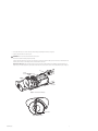
I N S T A L L A T I O N
®
ExSite™ Series
Explosionproof
Camera Module
C1303M-B (5/05)
Important Safety Instructions
1. Read these instructions.
2. Keep these instructions.
3. Heed all warnings.
4. Follow all instructions.
5. Do not block any ventilation openings. Install in accordance with the manufacturer’s instructions.
6. To reduce the risk of ignition of hazardous atmospheres, disconnect the equipment from the supply circuit before opening. Keep assembly
tightly closed when in operation.
7. The maximum ambient temperature range is -76°F to 140°F (-60°C to 60°C).
8. Only use attachments/accessories specified by the manufacturer.
9. Use only with the cart, stand, tripod, bracket, or table specified by the manufacturer, or sold with the apparatus. When a cart is used, use
caution when moving the cart/apparatus combination to avoid injury from tip-over.
10. Refer all servicing to qualified service personnel. Servicing is required when the apparatus has been damaged in any way, such as powersupply cord or plug is damaged, liquid has been spilled or objects have fallen into the apparatus, the apparatus has been exposed to rain or
moisture, does not operate normally, or has been dropped.
11. Installation should be done only by qualified personnel and conform to all local codes.
12. Unless the unit is specifically marked as a NEMA Type 3, 3R, 3S, 4, 4X, 6, or 6P enclosure, it is designed for indoor use only and it must not
be installed where exposed to rain and moisture.
13. Use only installation methods and materials capable of supporting four times the maximum specified load.
14. Use stainless steel hardware to fasten the mount to outdoor surfaces.
15. AN ALL-POLE MAINS SWITCH with a contact separation of at least 3 mm in each pole shall be incorporated in the electrical installation of
the building.
16. A readily accessible disconnect device shall be incorporated in the building installation wiring.
17. CAUTION: These servicing instructions are for use by qualified service personnel only. To reduce the risk of electric shock do not perform
any servicing other that contained in the operating instructions unless you are qualified to do so.
18. Only use replacement parts recommended by Pelco.
The product and/or manual may bear the following marks:
This symbol indicates that dangerous voltage constituting a risk of electric shock is present
within this unit.
This symbol indicates that there are important operating and maintenance instructions in the
literature accompanying this unit.
CAUTION:
RISK OF ELECTRIC SHOCK.
DO NOT OPEN.
WARNING: HAZARDOUS MOVING PARTS. KEEP FINGERS AND OTHER BODY PARTS AWAY.
WARNING: To reduce the risk of ignition of hazardous atmospheres, disconnect the
equipment from the supply circuit before opening. Keep assembly tightly closed when
operating.
WARNING: To reduce the risk of ignition of hazardous atmospheres, conduit runs must have
a sealing fitting connected within 2 inches of the enclosure.
TO REDUCE THE RISK OF IGNITION, DO NOT OPEN WHEN AN EXPLOSIVE GAS ATMOSPHERE
MAY BE PRESENT.
C1303M-B (5/05)
3
Getting Started
Thank you for purchasing Pelco’s ExSite™ Series explosionproof integrated positioning system. This manual includes instructions for installing the
camera module for the ExSite Series system. For complete system installation instructions, refer to the installation manual placed in the pan and
tilt box.
WARNING: Do not connect the power module to a supply circuit unless all ExSite system components (pan and tilt, camera module, and
power module) are installed.
Once the complete system is installed, refer to the operation/programming manual shipped with the camera module for instructions on how to
operate and program your system.
4
C1303M-B (5/05)
Installation
To install the camera module do the following:
1. Refer to Figure 1. Loosen the set screw at the back of the enclosure with the provided 1.5 mm Allen wrench.
SET SCREW
Figure 1. Loosen Setscrew
2. Use the supplied spanner wrench to loosen the back of the camera enclosure (refer to Figure 2). Once the back is loose, use your hands to
continue to loosen it until it can be removed.
WARNING: To avoid thread damage, carefully remove the back of the enclosure. Never use force to remove the back of the camera
enclosure.
CAMERA
ENCLOSURE
BACK
SPANNER
WRENCH
Figure 2. Remove Back Cap of Enclosure
C1303M-B (5/05)
5
3. Slide the camera module into the enclosure. Refer to Figure 3 to position the camera module properly in the enclosure. Carefully mate the
camera’s power connector to the mating connector located inside the enclosure.
Only models with wipers: The tab located inside the enclosure must be pointing down before installing the camera module (refer to
Figure 3). To position the tab, place the wiper located at the front of the enclosure in the center of the viewing window (refer to Figure 4).
WARNING: Do not force the camera module into the enclosure.
TAB
CENTER
NOTCHES
CAMERA
MODULE
CAMERA
ENCLOSURE
Figure 3. Install Camera Module
CENTER WIPER
Figure 4. Center Wiper
6
C1303M-B (5/05)
4. Refer to Figure 5 and do the following to install the arm of the wiper:
a.
Place the supplied green bushing on the stud located behind the handle of the camera module. The bushing should be in the same
orientation as shown in Figure 5.
b.
Install the wiper arm. Place the ridge of the arm in the notch of the enclosure tab and the slot of the arm over the green bushing.
5. Secure the arm of the wiper and the camera module with the supplied 8-32 Phillips flat head screw (refer to Figure 5).
SET TAB IN
CENTER POSITION
8-32 PHILLIPS FLAT
HEAD SCREW
ARM
CAMERA
MODULE
HANDLE
STUD
BUSHING
Figure 5. Install Wiper Arm
WARNINGS:
•
To avoid thread damage, carefully install the back cap to the enclosure.
•
Never force the back cap onto the end of the enclosure.
•
When installation is completed, there should be no gap between the back cap and the enclosure.
6. Reinstall the back cap on the enclosure by doing the following:
C1303M-B (5/05)
a.
Use your hands and turn the back cap clockwise until you can no longer turn it with your hands. The back cap should turn easily until
it comes in contact with the O-ring. If it does not turn easily, the threads are not aligned and thread damage will occur.
b.
Continue tightening the back cap with the supplied spanner wrench. There should be no gap between the back cap and the enclosure
when the back cap is tightened and properly installed.
c.
Once the back cap is installed, secure the back cap with the set screw using the supplied 1.5 mm Allen wrench.
7
Maintenance
CAMERA MODULE REPLACEMENT
The ExSite camera module can be replaced only with a camera module with the same model number. If a different camera model is installed in
an existing system, the system will not function and a message to contact the Pelco factory will appear on the screen.
DANGER: To reduce the risk of ignition of hazardous atmospheres, disconnect the equipment from the power supply before opening.
Keep assembly tightly closed when operating.
To replace the camera module do the following:
1. Remove the back cap of the camera enclosure. Refer to Figure 6 and do the following:
a.
Loosen the set screw with a 1.5 mm Allen wrench.
b.
Use the supplied spanner wrench to loosen the back cap of the camera enclosure. Once the back is loose, use your hands to continue
to loosen it until it can be removed.
CAMERA
ENCLOSURE
BACK
SET SCREW
SPANNER
WRENCH
Figure 6. Remove Back Cap of Camera Enclosure
2. Remove the 8-32 Phillips flat head screw that secures the camera module inside the enclosure, refer to Figure 7.
SET TAB IN
CENTER POSITION
8-32 PHILLIPS FLAT
HEAD SCREW
ARM
CAMERA
MODULE
HANDLE
STUD
BUSHING
Figure 7. Remove or Install Camera Module
8
C1303M-B (5/05)
3. For models with wipers, also remove the wiper arm and the green bushing from the unit (see Figure 7).
4. Slide the camera module out of the enclosure.
WARNING: Never force the camera module into the enclosure.
5. Install the new camera module by doing the following:
Slide the camera module into the enclosure. Refer to Figure 8 to position the camera module properly in the enclosure. Carefully mate the
camera’s power connector to the mating connector located inside the enclosure.
Only models with wipers: The tab located inside the enclosure must be pointing down before installing the camera module (refer to
Figure 8). To position the tab, place the wiper located at the front of the enclosure in the center of the viewing window (refer to Figure 9).
TAB
CENTER
NOTCHES
CAMERA
MODULE
CAMERA
ENCLOSURE
Figure 8. Install Camera Module
CENTER WIPER
Figure 9. Center Wiper
C1303M-B (5/05)
9
6. Refer to Figure 7 and do the following to reinstall the arm of the wiper:
a.
Reinstall the green bushing on the stud located behind the handle of the camera module.
b.
Reinstall the wiper arm. Place the ridge of the arm in the notch of enclosure tab and the slot of the arm over the green bushing.
7. Secure the camera module and the wiper arm with the 8-32 Phillips flat head screw (refer to Figure 7).
WARNINGS:
•
To avoid thread damage, carefully install the back cap to the enclosure.
•
Never force the back cap onto the end of the enclosure.
•
When installation is completed, there should be no gap between the back cap and the enclosure.
8. Reinstall the back cap on the enclosure by doing the following:
10
a.
Use your hands and turn the back cap clockwise until you can no longer turn it with your hands. The back cap should turn easily until
it comes in contact with the O-ring. If it does not turn easily, the threads are not aligned and thread damage will occur.
b.
Continue tightening the back cap with the supplied spanner wrench. There should be no gap between the back cap and the enclosure
when the back cap is tightened and properly installed.
c.
Once the back cap is installed, secure the back cap with the set screw using a 1.5 mm Allen wrench.
C1303M-B (5/05)
Specifications
Camera
Signal Format
Scanning System
Image Sensor
Effective pixels
NTSC
PAL
Horizontal Resolution
NTSC
PAL
Lens
Zoom
Zoom Speed
Horizontal
Angle of view
Focus
Maximum Sensitivity
at 35 IRE
NTSC
PAL
Sync System
White Balance
Shutter Speed
NTSC
PAL
Iris Control
Gain Control
Video Output
Video Signal to Noise
Day/Night (23X) Color
NTSC, PAL
2:1 interlace
1/4-inch CCD
LowLight™ (22X) Color
NTSC, PAL
2:1 Interlace
1/4-inch EXview HAD™ CCD
724 (H) x 494 (V)
724 (H) x 582 (V)
768 (H) x 494 (V)
752 (H) x 582 (V)
>470 TV lines
>470 TV lines
F1.6 (f = 3.6~82.8 mm optical)
23X optical, 10X digital
2.9/4.2/5.8 seconds
54° at 3.6 mm wide zoom
2.5° at 82.8 mm telephoto zoom
Automatic with manual override
>470 TV lines
>460 TV lines
F1.6 (f = 4~88 mm optical)
22X optical, 12X digital
2.4/3.9/6.3 seconds
47° at 4.0 mm wide zoom
2.2° at 88 mm telephoto zoom
Automatic with manual override
0.08 lux at 1/2 sec shutter (color)
0.3 lux at 1/60 sec shutter (B-W)
0.013 lux at 1/2 sec shutter (B-W)
0.08 lux at 1/1.5 sec shutter (color)
0.3 lux at 1/50 sec shutter (B-W)
0.013 lux at 1/1.5 sec shutter (B-W)
Internal/AC line lock, phase adjustable via
remote control, V-Sync*
Automatic with manual override*
Automatic (electronic iris)/Manual
1/2~1/30,000*
1/1.5~1/30,000*
Automatic Iris Control with manual override*
Automatic/OFF*
1 Vp-p, 75 ohms
>50 dB
0.02 lux at 1/2 sec shutter
0.02 lux at 1/1.5 sec shutter
Internal/AC line lock, phase adjustable via remote
control, V-Sync*
Automatic with manual override*
Automatic (electronic iris)/Manual
1/2~1/30,000*
1/1.5~1/30,000*
Automatic Iris Control with manual override*
Automatic/OFF*
1 Vp-p, 75 ohms
>50 dB
*Manual control of camera setup functions can be done with CM6700, CM6800, CM8500, CM9500, CM9740, CM9760, CM9770,
CM9780, KBD200A, KBD300A, and MPT9500 controllers, but not with CM7500, MPT9000, or KBD9000 controllers.
REVISION HISTORY
Manual #
C1303M
C1303M-A
C1303M-B
Date
11/04
2/05
5/05
Comments
Original version.
Added maintenance section for camera module replacement.
Revised instructions for models with wipers.
Pelco and the Pelco logo are registered trademarks of Pelco.
ExSite and LowLight are trademarks of Pelco.
EXview HAD is a trademark of Sony Corporation.
C1303M-B (5/05)
©Copyright 2005, Pelco. All rights reserved.
11
Worldwide Headquarters
3500 Pelco Way
Clovis, California 93612 USA
USA & Canada
Tel: 800/289-9100
Fax: 800/289-9150
International
Tel: 1-559/292-1981
Fax: 1-559/348-1120
www.pelco.com
ISO9001
United States
|
Canada
|
United Kingdom
|
The Netherlands
| Singapore | Spain | Scandinavia | France | Middle East