1
Installation and Assembly:
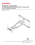
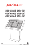
Peerless Ultra-Slim Articulating Mount for Samsung 46"
and 55" C9000 LED displays
Models: SUAC9000
Max UL Load Capacity: 75 lb (34 kg)
3215 W. North Ave. • Melrose Park, IL • (800) 865-2112 or (708) 865-8870 • Fax: (708) 865-2941 • www.peerlessmounts.com
ISSUED: 10-01-10 SHEET #: 095-9354-1
NOTE: Read entire instruction sheet before you start installation and assembly.
WARNING
• Do not begin to install your Peerless product until you have read and understood the instructions and warnings
contained in this Installation Sheet. If you have any questions regarding any of the instructions or warnings, for US
customers please call Peerless customer care at 1-800-865-2112, for all international customers, please contact
your local distributor.
• This product should only be installed by someone of good mechanical aptitude, has experience with basic building
construction, and fully understands these instructions.
• Make sure that the supporting surface will safely support the combined load of the equipment and all attached
hardware and components.
• Never exceed the Maximum UL Load Capacity. See page one.
• If mounting to wood wall studs, make sure that mounting screws are anchored into the center of the studs. Use of
an "edge to edge" stud finder is highly recommended.
• Always use an assistant or mechanical lifting equipment to safely lift and position equipment.
• Tighten screws firmly, but do not overtighten. Overtightening can damage the items, greatly reducing their holding
power.
• This product is intended for indoor use only. Use of this product outdoors could lead to product failure and personal
injury.
• This product was designed to be installed on the following wall construction only;
WALL CONSTRUCTION
HARDWARE REQUIRED
•
•
•
•
•
•
Included
Included
Included
Included
Contact Qualified Professional (Not evaluated by UL)
Contact Qualified Professional (Not evaluated by UL)
Wood Stud
Wood Beam
Solid Concrete
Cinder Block
Brick
Other or unsure?
Tools Needed for Assembly
•
•
•
•
•
•
stud finder ("edge to edge" stud finder is recommended)
phillips screwdriver
drill
5/16" (8 mm) bit for concrete and cinder block wall
5/32" (4 mm) bit for wood stud wall
level
Table of Contents
Parts List................................................................................................................................................................................. 3
Wall installation ...................................................................................................................................................................4, 5
Installing Adapter plates to screen..........................................................................................................................................6
Mounting Flat Panel Screen ...................................................................................................................................................8
2 of 11
ISSUED: 10-01-10 SHEET #: 095-9354-1
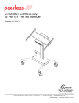
Before you begin, make sure all parts shown are included with your product.
Parts List
A
B
C
D
E
F
G
H
I
J
K
L
M
N
Description
wall arm assembly
upper mounting plate
lower mounting plate
wood screw
concrete anchor
security driver
fastener cap
cable clip
short cable tie
snap caps
8-32 x 1/4" flat head thread
forming screw
1/4-20 x 1/2" hex head
thread forming screw
M4 x 16 mm phillips screw
long cable tie
Qty.
1
1
1
4
4
1
8
1
3
4
4
Part #
046-4176
046-4177
046-4178
500-1090
590-0320
560-1133
046-4096
046-4137
560-2004
560-2029
520-2622
4
520-2592
4
2
520-2088
590-2168
A
Parts may appear slightly different than illustrated.
B
D
K
C
E
F
H
G
L
I
M
J
N
3 of 11
ISSUED: 10-01-10 SHEET #: 095-9354-1
Installation to Wood Stud Wall
WARNING
• Installer must verify that the supporting surface will safely support the combined load of the equipment and all
attached hardware and components.
• Tighten wood screws so that wall plate is firmly attached, but do not overtighten. Overtightening can damage the
screws, greatly reducing their holding power.
• Never tighten in excess of 80 in. • lb (9 N.M.).
• Make sure that mounting screws are anchored into the center of the stud. The use of an "edge to edge" stud finder
is highly recommended.
• Hardware provided is for attachment of mount through standard thickness drywall or plaster into wood studs.
Installers are responsible to provide hardware for other types of mounting situations (not evaluated by UL).
1
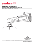
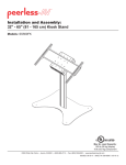
Use a stud finder to locate the edges of the studs. Use of an edge-to-edge stud finder is highly recommended.
Based on their edges, draw a vertical line down each stud’s center. Center of screen mounting plate will be
2.5" offset from center of outer mounting slot as shown in figure 1.1 or will be 0.19" offset from center of inner
mounting slot as shown in figure 1.2. Place wall arm (A) on wall as template, level, and mark the center of four
mounting holes. Top mounting slot will be X" above the screen center as shown in figure 1.1 and chart 1.
Drill four 5/32" dia. holes to a minimum depth of 2.5". Secure wall arm (A) to wall with four wood screws (D) as
shown in figure 1.2. NOTE: Be sure arrow is pointing up when mounting wall arm (A) to wall as shown in figure
1.1. Level, then tighten all fasteners.
Insert eight fastener caps (G) into wall plate mounting holes.
fig. 1.1
2.5"
(64 mm)
fig. 1.2
ARROW
0.19"
(5 mm)
X"
SCREEN
MOUNTING PLATE
Chart 1
for 46" display
for 55" display
10.7" (272mm)
9.1" (231mm)
= CENTER OF SCREEN
G
D
A
4 of 11
ISSUED: 10-01-10 SHEET #: 095-9354-1
Installation to Solid Concrete or Cinder Block
WARNING
• When installing Peerless wall mounts on cinder block, verify that you have a minimum of 1-3/8" (35 mm) of actual
concrete thickness in the hole to be used for the concrete anchors. Do not drill into mortar joints! Be sure to mount
in a solid part of the block, generally 1" (25 mm) minimum from the side of the block. Cinder block must meet ASTM
C-90 specifications. It is suggested that a standard electric drill on slow setting is used to drill the hole instead of a
hammer drill to avoid breaking out the back of the hole when entering a void or cavity.
• Concrete must be 2000 psi density minimum. Lighter density concrete may not hold concrete anchor.
• Installer must verify that the supporting surface will safely support the combined load of the equipment and all attached hardware and components.
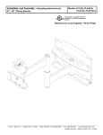
1
NOTE: Wall arm assembly (A) must be mounted to
wall using inner mounting holes.
Make sure that wall arm assembly is level and use
wall plate as a template to mark four mounting holes.
Top mounting slot will be X" above the screen center
as shown in figure 1.1 and chart 1 on page 4. Drill four
5/16" (8 mm) dia. holes to a minimum depth of 2.5"
(64 mm). Insert anchors (E) in holes flush with wall as
shown. Place wall arm assembly over anchors and
secure with wood screws (D). Level, then tighten all
fasteners. Insert eight fastener caps (G) into mounting
holes.
concrete
surface
1
E
Drill holes and insert anchors (E).
2
A
F
D
NOTE: Be sure arrow of label is pointing up when
mounting wall arm assembly (A) to wall as shown in
figure 1.1.
E
Place plate (A) over anchors (E) and secure with screws (D).
3
WARNING
• Tighten screws so that wall plate is firmly attached,
but do not overtighten. Overtightening can damage
screws, greatly reducing their holding power.
Tighten all fasteners.
• Never tighten in excess of 80 in. • lb (9 N.M.).
• Always attach concrete anchors directly to loadbearing concrete.
SOLID CONCRETE
CINDER BLOCK
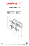
• Never attach concrete anchors to concrete covered
with plaster, drywall, or other finishing material.
If mounting to concrete surfaces covered with a
finishing surface is unavoidable (not evaluated by
UL), the finishing surface must be counterbored
as shown below. Be sure concrete anchors do not
pull away from concrete when tightening screws. If
plaster/drywall is thicker than 5/8" (16 mm), custom
fasteners must be supplied by installer (not evaluated
by UL).
CUTAWAY VIEW
INCORRECT
concrete
wall
plate
plaster/
dry wall
E
D
G
CORRECT
A
concrete
wall
plate
plaster/
dry wall
5 of 11
ISSUED: 10-01-10 SHEET #: 095-9354-1
WARNING
• Be sure to carry display upright, from the top and bottom edges, or damage to display may occur.
2
Follow instruction manual included with display to remove display from stand.
Set display on a flat, level surface. Refer to display manufacturer's installation guide for recommended careful
handling. Remove two M4 chrome plated screws from Ultra-Slim wall mount bar. Save all screws. Install eight
standoff screws (included with display) into eight mounting holes on bottom of display.
M5 CHROME SCREWS
DISPLAY
STANDOFFS
WARNING
• Do not assemble mounting plates (B,C) on top of display or damage to display may occur.
3
Assemble upper mounting plate (B) to lower mounting plate (C) using four 8-32 x 1/4" flat head thread forming
screws (K). Use configuration as shown in figures 3.1 and 3.2.
B
B
C
C
K
K
FIG. 3.1
FOR 46" DISPLAYS
FIG. 3.2
FOR 55" DISPLAYS
6 of 11
ISSUED: 10-01-10 SHEET #: 095-9354-1
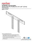
4
Install two 1/4-20 x 1/2" thread forming screws (L) into lower mounting plate (C) leaving 1/8" exposed thread as
shown below.
C
L
5
Set control box into lower mount plate (C) and place assembly onto back of display.
Secure assembly to back of display by reinstalling two M4 chrome plated screws (included with display) into ultraslim wall mount bar, four M4 black phillips screws (included with display) into lower mounting holes of control box,
and four M4 x 16 mm phillips screws (M) into upper mounting holes of control box.
ULTRA-SLIM WALL
MOUNT BAR
M4 CHROME SCREWS
M
DISPLAY
M4 BLACK SCREWS
CONTROL
BOX
7 of 11
ISSUED: 10-01-10 SHEET #: 095-9354-1
Mounting Flat Panel Screen
WARNING
• Tighten screws so screen brackets are firmly attached to screen. Do not tighten with excessive force. Overtightening
can cause stress damage to screws, greatly reducing their holding power and possibly causing screw heads to
become detached. Tighten to 40 in. • lb (4.5 N.M.) maximum torque.
6
Hook two 1/4-20 x 1/2" thread forming screws (L) onto top slots of front plate as shown in figure 6.1.
Fasten two 1/4-20 x 1/2" thread forming screws (L) into bottom mounting holes as shown in figure 6.2.
Tighten all screws.
FRONT PLATE
fig. 6.1
L
fig. 6.2
8 of 11
ISSUED: 10-01-10 SHEET #: 095-9354-1
Cable Management
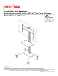
7
Cables may be routed using short cable ties (I).
Use holes on bottom of lower mounting plate (C) with cable ties (I) to secure cables as shown below.
I
CABLES
Cables may be routed using cable clip (H).
Slip cable clip (H) onto bottom of center joint as shown in figure 7.1 and secure cables to cable clip using long cable tie
(N) as shown in figure 7.2.
Secure cables to bottom of wall plate using cable tie (N) as shown below.
WALL PLATE
SLOTS
N
CENTER
JOINT
H
fig. 7.1
N
CABLES
CABLES
fig. 7.2
9 of 11
ISSUED: 10-01-10 SHEET #: 095-9354-1
© 2009, Peerless Industries, Inc. All rights reserved.
All other brand and product names are trademarks or registered trademarks of their respective owners.
Roll Adjustment
8
Adapter plate may be rolled +/- 5°.
Loosen four M6 nylock nuts half a turn, grasp edges of display and roll screen to desired position as shown.
Retighten four M6 nylock nuts and place four snap caps (J) onto M6 nylock nuts.
CAUTION
• Do not tighten joint screws. Doing so may cause
damage to screws, greatly reducing its holding
power.
JOINT SCREWS
M6 NYLOCK NUTS
10 of 11
ISSUED: 10-01-10 SHEET #: 095-9354-1
© 2009, Peerless Industries, Inc. All rights reserved.
All other brand and product names are trademarks or registered trademarks of their respective owners.
LIMITED FIVE-YEAR WARRANTY
Peerless Industries, Inc. establishes a warranty period of five years for products manufactured or supplied by Peerless. This period commences from the date of
sale of the product to the original consumer, but will in no case last for more than six years after the date of the product’s manufacture. During the warranty period
such products will be free from defects in material and workmanship, provided they are installed and used in compliance with the instructions established by
Peerless Industries, Inc. Subject to applicable legal requirements, during the warranty period Peerless will repair or replace, or refund the purchase price of, any
such product which fails to conform with this warranty.
Any other warranties prescribed by the law which may apply with respect to such products also are limited in duration to the warranty period specified in this
Limited Five-Year Warranty.
This warranty does not cover damage caused by (a) service or repairs by the customer or a person who is not authorized for such service or repairs by Peerless
Industries, Inc., (b) the failure to utilize proper packing when returning the product, (c) incorrect installation or the failure to follow Peerless’ instructions or warnings
when installing, using or storing the product, or (d) misuse or accident, in transit or otherwise, including in cases of third party actions and force majeure.
In no event shall Peerless be liable for incidental or consequential damages or damages arising from the theft of any product, whether or not secured by a security
device which may be included with the product.
This Limited Five-Year Warranty is in lieu of all other warranties, expressed or implied, and is the sole remedy with respect to product defects. No retailer, dealer,
distributor, installer or other person is authorized to modify or extend this warranty or impose any obligation on Peerless in connection with the sale of any product
manufactured or supplied by Peerless.
This warranty gives specific legal rights, and you may also have other rights provided by the national legislation of the country in which you purchased such
product.
www.peerlessmounts.com
11 of 11
© 2008 Peerless Industries, Inc.
ISSUED: 10-01-10 SHEET #: 095-9354-1