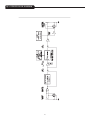
1
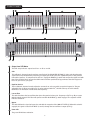
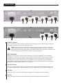
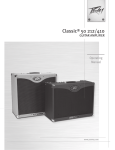
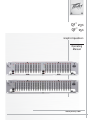
QF™ 231
QF™ 151
Graphic Equalizers
Operating
Manual
www.peavey.com
2
IMPORTANT SAFETY INSTRUCTIONS
WARNING: When using electrical products, basic cautions should always be followed, including the following:
1.
2.
3.
4.
5.
6.
7.
8.
9.
10.
11.
12.
13.
14.
15.
16.
17.
18.
19.
20.
Read these instructions.
Keep these instructions.
Heed all warnings.
Follow all instructions.
Do not use this apparatus near water.
Clean only with a dry cloth.
Do not block any of the ventilation openings. Install in accordance with manufacturer’s instructions.
Do not install near any heat sources such as radiators, heat registers, stoves or other apparatus (including amplifiers) that
produce heat.
Do not defeat the safety purpose of the polarized or grounding-type plug. A polarized plug has two blades with one wider than
the other. A grounding type plug has two blades and a third grounding plug. The wide blade or third prong is provided for your
safety. If the provided plug does not fit into your outlet, consult an electrician for replacement of the obsolete outlet.
Protect the power cord from being walked on or pinched, particularly at plugs, convenience receptacles, and the point they exit
from the apparatus.
Only use attachments/accessories provided by the manufacturer.
Use only with a cart, stand, tripod, bracket, or table specified by the manufacturer, or sold with the apparatus. When a cart is
used, use caution when moving the cart/apparatus combination to avoid injury from tip-over.
Unplug this apparatus during lightning storms or when unused for long periods of time.
Refer all servicing to qualified service personnel. Servicing is required when the apparatus has been damaged in any way, such
as power-supply cord or plug is damaged, liquid has been spilled or objects have fallen into the apparatus, the apparatus has
been exposed to rain or moisture, does not operate normally, or has been dropped.
Never break off the ground pin. Write for our free booklet “Shock Hazard and Grounding.” Connect only to a power supply of the
type marked on the unit adjacent to the power supply cord.
If this product is to be mounted in an equipment rack, rear support should be provided.
Note for UK only: If the colors of the wires in the mains lead of this unit do not correspond with the terminals in your plug‚
proceed as follows:
a) The wire that is colored green and yellow must be connected to the terminal that is marked by the letter E‚ the earth symbol‚
colored green or colored green and yellow.
b) The wire that is colored blue must be connected to the terminal that is marked with the letter N or the color black.
c) The wire that is colored brown must be connected to the terminal that is marked with the letter L or the color red.
This electrical apparatus should not be exposed to dripping or splashing and care should be taken not to place objects
containing liquids, such as vases, upon the apparatus.
The on/off switch in this unit does not break both sides of the primary mains. Hazardous energy can be present inside the
chassis when the on/off switch is in the off position. The mains plug or appliance coupler is used as the disconnect device, the
disconnect device shall remain readily operable.
Exposure to extremely high noise levels may cause a permanent hearing loss. Individuals vary considerably in susceptibility to
noise-induced hearing loss, but nearly everyone will lose some hearing if exposed to sufficiently intense noise for a sufficient
time. The U.S. Government’s Occupational Safety and Health Administration (OSHA) has specified the following permissible
noise level exposures:
Duration Per Day In Hours
8
6
4
3
2
1 1⁄2
1
1⁄2
1⁄4 or less
Sound Level dBA, Slow Response
90
92
95
97
100
102
105
110
115
According to OSHA, any exposure in excess of the above permissible limits could result in some hearing loss. Ear plugs or protectors to
the ear canals or over the ears must be worn when operating this amplification system in order to prevent a permanent hearing loss, if
exposure is in excess of the limits as set forth above. To ensure against potentially dangerous exposure to high sound pressure levels, it is
recommended that all persons exposed to equipment capable of producing high sound pressure levels such as this amplification system be
protected by hearing protectors while this unit is in operation.
SAVE THESE INSTRUCTIONS!
3
WICHTIGE SICHERHEITSHINWEISE
ACHTUNG: Beim Einsatz von Elektrogeräten müssen u.a. grundlegende Vorsichtsmaßnahmen befolgt werden:
1.
2.
3.
4.
5.
6.
7.
8.
9.
10.
11.
12.
13.
14.
15.
16.
17.
18.
19.
20.
LesenSiesichdieseAnweisungendurch.
BewahrenSiedieseAnweisungenauf.
BeachtenSiealleWarnungen.
BefolgenSiealleAnweisungen.
SetzenSiediesesGerätnichtinderNähevonWasserein.
ReinigenSieesnurmiteinemtrockenenTuch.
BlockierenSiekeinederLüftungsöffnungen.FührenSiedieInstallationgemäßdenAnweisungendesHerstellersdurch.
InstallierenSiedasGerätnichtnebenWärmequellenwieHeizungen,Heizgeräten,ÖfenoderanderenGeräten(auchVerstärkern),
dieWärmeerzeugen.
BeeinträchtigenSienichtdieSicherheitswirkungdesgepoltenSteckersbzw.desErdungssteckers.EingepolterSteckerweist
zweiStifteauf,vondeneneinerbreiteristalsderandere.EinErdungssteckerweistzweiStifteundeinendrittenErdungsstiftauf.
DerbreiteStiftbzw.derdritteStiftdientIhrerSicherheit.SolltederbeiliegendeSteckernichtinIhreSteckdosepassen,wenden
SiesichbitteaneinenElektriker,umdieungeeigneteSteckdoseaustauschenzulassen.
SchützenSiedasNetzkabel,sodassniemanddarauftrittoderesgeknicktwird,insbesondereanSteckernoderBuchsenund
ihrenAustrittsstellenausdemGerät.
VerwendenSienurdievomHerstellererhältlichenZubehörgeräteoderZubehörteile.
VerwendenSienureinenWagen,Stativ,Dreifuß,TrägeroderTisch,derdenAngabendesHerstellersentsprichtoderzusammen
mitdemGerätverkauftwurde.WirdeinWagenverwendet,bewegenSiedenWagenmitdemdaraufbefindlichenGerätbesonders
vorsichtig,damiternichtumkipptundmöglicherweisejemandverletztwird.
TrennenSiedasGerätwährendeinesGewittersoderwährendlängererZeiträume,indenenesnichtbenutztwird,vonder
Stromversorgung.
LassenSiesämtlicheWartungsarbeitenvonqualifiziertenKundendiensttechnikerndurchführen.EineWartungisterforderlich,
wenndasGerätinirgendeinerArtbeschädigtwurde,etwawenndasNetzkabeloderderNetzsteckerbeschädigtwurden,
FlüssigkeitoderGegenständeindasGerätgelangtsind,dasGerätRegenoderFeuchtigkeitausgesetztwurde,nichtnormal
arbeitetoderheruntergefallenist.
DerErdungsstiftdarfnieentferntwerden.AufWunschsendenwirIhnengerneunserekostenloseBroschüre„ShockHazardand
Grounding“(GefahrdurchelektrischenSchlagundErdung)zu.SchließenSienurandieStromversorgungderArtan,dieam
GerätnebendemNetzkabelangegebenist.
WenndiesesProduktineinGeräte-Rackeingebautwerdensoll,musseineVersorgungüberdieRückseiteeingerichtetwerden.
Hinweis–NurfürGroßbritannien:SolltedieFarbederDrähteinderNetzleitungdiesesGerätsnichtmitdenKlemmeninIhrem
Steckerübereinstimmen,gehenSiefolgendermaßenvor:
a)Dergrün-gelbeDrahtmussandiemitE(SymbolfürErde)markiertebzw.grüneodergrün-gelbeKlemmeangeschlossen
werden.
b)DerblaueDrahtmussandiemitNmarkiertebzw.schwarzeKlemmeangeschlossenwerden.
c)DerbrauneDrahtmussandiemitLmarkiertebzw.roteKlemmeangeschlossenwerden.
DiesesGerätdarfnichtungeschütztWassertropfenundWasserspritzernausgesetztwerdenundesmussdaraufgeachtet
werden,dasskeinemitFlüssigkeitengefüllteGegenstände,wiez.B.Blumenvasen,aufdemGerätabgestelltwerden.
DerNetzschalterindieserEinheitbrichtbeideSeitenvondenprimärenHaupleitungennicht.GerfährlicheEnergiekann
anwesendinnerhalbdesChassissein,wennherNetzschalterimabPoistionist.DieHauptleitungenstöpselnzuoder
Gerätkupplungistbenutzt,währenddasVorrichtungabschaltet,dasschaltetVorrichtungwirdbleibensogleichhantierbarab.
BelastungdurchextremhoheLärmpegelkannzudauerhaftemGehörverlustführen.DieAnfälligkeitfürdurchLärmbedingten
GehörverlustistvonMenschzuMenschverschieden,dasGehörwirdjedochbeijedemingewissemMaßegeschädigt,derüber
einenbestimmtenZeitraumausreichendstarkemLärmausgesetztist.DieUS-Arbeitsschutzbehörde(OccupationalandHealth
Administration,OSHA)hatdiefolgendenzulässigenPegelfürLärmbelastungfestgelegt:
Dauer pro Tag in Stunden
Geräuschpegel dBA, langsame Reaktion
8
6
4
3
2
1 1⁄2
1
1⁄2
1⁄4 oder weniger
90
92
95
97
100
102
105
110
115
LautOSHAkannjedeBelastungüberdenobenstehendenzulässigenGrenzwertenzueinemgewissenGehörverlustführen.SolltedieBelastung
dieobenstehendenGrenzwerteübersteigen,müssenbeimBetriebdiesesVerstärkungssystemsOhrenstopfenoderSchutzvorrichtungen
imGehörgangoderüberdenOhrengetragenwerden,umeinendauerhaftenGehörverlustzuverhindern.Umsichvoreinermöglicherweise
gefährlichenBelastungdurchhoheSchalldruckpegelzuschützen,wirdallenPersonenempfohlen,diemitGerätenarbeiten,diewiedieses
VerstärkungssystemhoheSchalldruckpegelerzeugenkönnen,beimBetriebdiesesGerätseinenGehörschutzzutragen.
BEWAHREN SIE DIESE SICHERHEITSHINWEISE AUF!
4
INSTRUCTIONS IMPORTANTES DE SECURITE
ATTENTION: L’utilisation de tout appareil électrique doit être soumise aux precautions d’usage incluant:
1.
2.
3.
4.
5.
6.
7.
8.
9.
10.
11.
12.
13.
14.
15.
16.
17.
18.
19.
20.
Lirecesinstructions.
Gardezcemanuelpourdefuturesréférences.
Prétezattentionauxmessagesdeprécautionsdecemanuel.
Suivezcesinstructions.
N’utilisezpascetteunitéprochedeplansd’eau.
N’utilisezqu’untissusecpourlenettoyagedevotreunité.
N’obstruezpaslessystèmesderefroidissementdevotreunitéetinstallezvotreunitéenfonctiondesinstructionsdecemanuel.
Nepositionnezpasvotreunitéàproximitédetoutesourcedechaleur.
Connecteztoujoursvotreunitésurunealimentationmuniedeprisedeterreutilisantlecordond’alimentationfourni.
Protégezlesconnecteursdevotreunitéetpositionnezlescablagespourévitertoutesdéconnexionsaccidentelles.
N’utilisezquedesfixationsapprouvéesparlefabriquant.
Lorsdel’utilsationsurpiedoupoledesupport,assurezdanslecasdedéplacementdel’ensembleenceinte/supportdeprévenir
toutbasculementintempestifdecelui-ci.
Ilestconseillédedéconnecterdusecteurvotreunitéencasd’orageoudeduréeprolongéesansutilisation.
Seuluntechnicienagrééparlefabriquantestàmêmederéparer/contrôlervotreunité.Celle-cidoitêtrecontrôléesielleasubit
desdommagesdemanipulation,d’utilisationoudestockage(humidité,…).
Nedéconnectezjamaislaprisedeterredevotreunité.
Sivotreunitéestdestinéeaetremontéeenrack,dessupportsarrieredoiventetreutilises.
NotepourlesRoyaumes-Unis:Silescouleursdeconnecteursducabled’alimentationnecorrespondpasauguidedelaprise
secteur,procédezcommesuit:
a)LeconnecteurvertetjaunedoitêtreconnectrerauterminalnotéE,indiquantlaprisedeterreoucorrespondantauxcouleurs
verteouverteetjauneduguide.
b)LeconnecteurBleudoitêtreconnectrerauterminalnotéN,correspondnatàlacouleurnoireduguide.
c)LeconnecteurmarrondoitêtreconnectrerauterminalnotéL,correspondantàlacouleurrougeduguide.
Cetéquipementélectriquenedoitenaucuncasêtreencontactavecunquelconqueliquideetaucunobjetcontenantunliquide,
vaseouautrenedevraitêtreposésurcelui-ci.
L'interrupter(on-off )danscetteuniténecassepaslesdeuxcôtésduprimaireprincipal.L'énergiehasardeusepeutêtre
preésentedanschâssisquandl'interrupter(on-off )estdansledelaposition.Lebouchonprincipalouatelaged'appareilest
utilisécommeledébrancherl'appareilresterafacilementopérable.
Uneexpositionàdehautsniveauxsonorespeutconduireàdesdommagesdel’écouteirréversibles.Lasusceptibilitéaubruit
varieconsidérablementd’unindividuàl’autre,maisunelargemajoritédelapopulationexpérienceraunepertedel’écouteaprès
uneexpositionàunefortepuissancesonorepouruneduréeprolongée.L’organismedelasantéaméricaine(OSHA)aproduitle
guideci-dessousenrapportàlaperteoccasionnée:
Durée par Jour (heures)
8
6
4
3
2
1 1⁄2
1
1⁄2
1⁄4 ou inférieur
Niveau sonore moyen (dBA)
90
92
95
97
100
102
105
110
115
D’aprèslesétudesmenéesparleOSHA,touteexpositionaudelàdeslimitesdécritesce-dessusentraineradespertesdel’écoutechezla
plupartdessujets.Leportdesystèmedeprotection(casque,oreilettedefiltrage,…)doitêtreobservélorsdel’opérationcetteunitéoudes
dommagesirréversiblespeuventêtreoccasionnés.Leportdecessystèmesdoitêtreobservépartoutespersonnessusceptiblesd’êtreexposéesàdesconditionsaudelàdeslimitesdécritesci-dessus.
GARDEZ CES INSTRUCTIONS!
5
INSTRUCCIONES IMPORTANTES PARA SU SEGURIDAD
CUIDADO: Cuando use productos electrónicos, debe tomar precauciones básicas, incluyendo las siguientes:
1.
2.
3.
4.
5.
6.
7.
8.
Leaestasinstrucciones.
Guardeestasinstrucciones.
Hagacasodetodoslosconsejos.
Sigatodaslasinstrucciones.
Nousaresteaparatocercadelagua.
Limpiarsolamenteconunatelaseca.
Nobloquearningunadelassalidasdeventilación.Instalardeacuerdoalasinstruccionesdelfabricante.
Noinstalarcercadeningunafuentedecalorcomoradiadores,estufas,hornosuotrosaparatos(incluyendoamplificadores)que
produzcancalor.
9.
Noretirelapatillaprotectoradelenchufepolarizadoodetipo“aTierra”.Unenchufepolarizadotienedospuntas,unadeellas
másanchaquelaotra.Unenchufedetipo“aTierra”tienedospuntasyunatercera“aTierra”.Lapuntaancha(latercera)se
proporcionaparasuseguridad.Sielenchufeproporcionadonoencajaensuenchufedered,consulteaunelectricistaparaque
reemplazesuenchufeobsoleto.
10.
Protejaelcabledealimentaciónparaquenoseapisadoopinchado,particularmenteenlosenchufes,huecos,ylospuntosque
salendelaparato.
11.
Usarsolamenteañadidos/accesoriosproporcionadosporelfabricante.
12.
Usarsolamenteuncarro,pie,trípode,osoporteespecificadoporelfabricante,ovendidojuntoalaparato.Cuandoseuseun
carro,tengacuidadoalmoverelconjuntocarro/aparatoparaevitarquesedañeenunvuelco.Nosuspendaestacajadeninguna
manera.
13.
Desenchufeesteaparatodurantetormentasocuandonoseausadodurantelargosperiodosdetiempo.
14.
Paracualquierreparación,acudaapersonaldeserviciocualificado.Serequierenreparacionescuandoelaparatohasidodañado
dealgunamanera,comocuandoelcabledealimentaciónoelenchufesehandañado,algúnlíquidohasidoderramadooalgún
objetohacaídodentrodelaparato,elaparatohasidoexpuestoalalluviaolahumedad,nofuncionademaneranormal,oha
sufridounacaída.
15.
NuncaretirelapatilladeTierra.Escríbanosparaobtenernuestrofolletogratuito“ShockHazardandGrounding”(“Peligrode
ElectrocuciónyTomaaTierra”).Conecteelaparatosóloaunafuentedealimentacióndeltipomarcadoalladodelcablede
alimentación.
16.Siesteproductovaaserenracadoconmásequipo,usealgúntipodeapoyotrasero.
17.
NotaparaelReinoUnidosolamente:Siloscoloresdeloscablesenelenchufeprincipaldeestaunidadnocorrespondenconlos
terminalesensuenchufe‚procedadelasiguientemanera:
a)ElcabledecolorverdeyazuldebeserconectadoalterminalqueestámarcadoconlaletraE‚elsímbolodeTierra(earth)‚
coloreadoenverdeoenverdeyamarillo.
b)ElcablecoloreadoenazuldebeserconectadoalterminalqueestámarcadoconlaletraNoelcolornegro.
c)ElcablecoloreadoenmarróndebeserconectadoalterminalqueestámarcadoconlaletraLoelcolorrojo.
18.Esteaparatoeléctriconodebesersometidoaningúntipodegoteoosalpicaduraysedebetenercuidadoparanoponerobjetos
quecontenganlíquidos,comovasos,sobreelaparato.
19.
Elinterruptordeen/lejosenestaunidadnorompeambosladosdelaredprimaria.Laenergíapeligrosapuedeserpresente
dentrodelchasiscuandoelinterruptordeen/lejosestáeneldelaposición.Eltapóndelaredoelacopladordelaparatoson
utilizadoscomoeldesconectadispositivo,eldesconectadispositivosequedaráfácilmenteoperable.
20.
Laexposiciónaaltosnivelesderuidopuedecausarunapérdidapermanenteenlaaudición.Lasusceptibilidadalapérdidade
audiciónprovocadaporelruidovaríasegúnlapersona,perocasitodoelmundoperderáalgodeaudiciónsiseexponeaun
nivelderuidosuficientemanteintensoduranteuntiempodeterminado.ElDepartamentoparalaSaludyparalaSeguridaddel
GobiernodelosEstadosUnidos(OSHA)haespecificadolassiguientesexposicionesalruidopermisibles: DuraciónporDíaenHoras
NiveldeSonidodBA,RespuestaLenta
8
6
4
3
2
11⁄2
1
1⁄2
1⁄4omenos
90
92
95
97
100
102
105
110
115
DeacuerdoalOSHA,cualquierexposiciónqueexcedaloslímitesarribaindicadospuedeproduciralgúntipodepérdidaenlaaudición.
Protectoresparaloscanalesauditivosotaponesparalosoídosdebenserusadoscuandoseopereconestesistemadesonidoparaprevenirunapérdidapermanenteenlaaudición,silaexposiciónexcedeloslímitesindicadosmásarriba.Paraprotegersedeunaexposicióna
altosnivelesdesonidopotencialmentepeligrosa,serecomiendaquetodaslaspersonasexpuestasaequipamientocapazdeproduciraltos
nivelesdepresiónsonora,talescomoestesistemadeamplificación,seencuentrenprotegidasporprotectoresauditivosmientrasestaunidadestéoperando.
GUARDE ESTAS INSTRUCCIONES!
6
™
QF
Series
Graphic Equalizers
ENGLISH
Thank you for purchasing a Peavey Electronics QF Series graphic equalizer. The QF family features one dual-channel
model and one single-channel unit, all incorporating Peavey’s legendary low-noise, low-distortion design. Ruggedly
constructed, QF Series EQs have 45 mm, center-detented control sliders enclosed in metal for durability. These two
rack-space units also offer ±15 dB gain control and an LED display indicating output level. Other shared features include
switchable low-cut filters, +21 dBu balanced inputs and outputs, and bypass switches. QF Series equalizer filters are
set at ISO center frequencies within 3% accuracy. Whether on stage, in the studio, or simply tweaking your home hi-fi
system, the QF Series has an EQ for you.
Please read this guide carefully to ensure your personal safety as well as the safety of your equipment.
Features
QF 215
• Dual channel (15 bands per channel)
• 2/3 octave filter sets
• ISO center frequencies within 3% accuracy
• 25 Hz to 16 kHz effective equalization range
• 45 mm, center-detent control sliders enclosed in metal for durability
• Constant Q filters
• Output level LEDs (-12 to +12 dB)
• 12 dB boost/18 dB cut per band
• 18 dB per octave 40 Hz low-cut filter with status LED
• +/-15 dB gain control
• Improved Peavey FLS® (Feedback Locating System)
• XLR and 1/4 inch TRS inputs/outputs for balanced or unbalanced operation
QF 131
• 31-band graphic EQ with +12 dB boost/-18 dB cut per band
• 1/3 octave filter sets
• ISO center frequencies within 3% accuracy
• 45 mm, center-detent control sliders enclosed in metal for durability
• Constant Q filters
• Output level LEDs (-12 to +12 dB)
• 18 dB per octave 40 Hz low-cut filter with status LED
• +/-15 dB gain control
• 20 Hz to 20 kHz effective equalization range
• XLR and 1/4" TRS inputs/outputs for balanced or unbalanced operation
• Bypass switch with status LED
• Improved FLS® (Feedback Locating System) circuitry for greater sensitivity
7
front p a nel
1
4
1
1
3
5
1
4
2
5
4
2
2
3
6
3
5
6
Output Level LED Meter
This LED array indicates output level from –12 dB to +12 dB.
2
Gain
This calibrated, detented control regulates overall gain of the EQUALIZER SECTION (3). Unity gain throughout the
signal chain can be maintained by recovering lost signal gain at this point. The equalization process may result in
noticeable signal loss. To compensate for this loss, engage the BYPASS (5) switch and compare the signal level with
that of the equalized level. Increase the GAIN control until the equalized level approximates that of the bypassed
level. Let your ears be your guide.
3
Equalizer Section
These calibrated, detented controls adjust the amount of cut or boost at their respective frequencies. They are
adjustable from 18 dB cut to 12 dB boost. For units equipped with FLS®, the LED at the top of each band will
illuminate as an indication of feedback at that frequency.
4
Low-cut filter
This switch activates the low-cut filter that rejects frequencies below 40 Hz. Frequency roll off is 24 dB per octave
with the switch engaged. This filter will operate even with the BYPASS (5) switch engaged. The adjacent red LED
indicates activation.
5
Bypass
This switch allows the signal to bypass the unit with the exception of the LOW-CUT FILTER (4). When this switch is
engaged, the signal is routed from INPUT (10 and 11) through the low-cut filter to output (8 and 9).
6
Power LED
The green LED indicates activation.
8
R E A R p a nel
7
8
9
8
7
7
10
8
9
8
10
8
9
8
10
IEC Mains Connector
This is a standard IEC power connector. An AC mains cord having the appropriate AC plug and ratings for
the intended operating voltage is included in the carton.
NOTE: Never break off the ground pin on any equipment. It is provided for your safety. If the
outlet used does not have a ground pin, a suitable grounding adapter should be used and the
third wire should be grounded properly. To prevent the risk of shock or fire hazard, always be sure
that the equalizer and all associated equipment is properly grounded.
NOTE: FOR UK ONLY
If the colors of the wires in the mains lead of this unit do not correspond with the colored markings
identifying the terminals in your plug, proceed as follows: (1) The wire that is colored green and yellow
must be connected to the terminal that is marked by the letter E, the earth symbol, colored green, or
colored green and yellow. (2) The wire that is colored blue must be connected to the terminal that is
marked with the letter N or the color black. (3) The wire that is colored brown must be connected to the
terminal that is marked with the letter L or the color red.
8
TRS Balanced Output
These 1/4" tip/ring/sleeve (stereo) jacks provide balanced output when used with TRS connectors and
2-conductor shielded cables. When used with a mono 1/4" (TS) phone plug, the output is unbalanced.
9
XLR Output
These male 3-pin connectors provide balanced output when used with female XLR connectors.
10
XLR Input
These female 3-pin connectors provide balanced input when used with male XLR connectors.
9
QF ™ Series Block Diagram
10
SPECIFICATIONS* QF™ 131 Filter Q Filter Frequencies (Hz) QF™ 215
4.77 2.3
20, 25, 32, 40, 50, 63, 80, 100, 125, 160, 200, 250, 315, 400, 500, 630, 800, 1 k, 1.25 k, 1.6 k, 2 k, 2.5 k,
3.15 k, 4 k, 5 k, 6.3 k, 8 k,
10 k, 12.5 k, 16 k, 20 k
Maximum Boost
and Cut Filter 25, 40, 63, 100, 160,
250, 400, 630, 1 k, 1.6 k,
2.5 k, 4 k, 6.3 k, 10 k, 16 k
+12 dB / -18 dB Output Noise
Bypass Mode Filter Mode (Flat)
+12 dB / -18 dB
-101 dBV -95 dBV
-100 dBv
-98 dBV
ALL MODELS
Frequency Response:
± 1 dB (20 Hz – 20 kHz)
Distortion:
.002% (20 Hz – 20 kHz)
Input Impedance: Balanced 20 k ohms (equal impedances to ground)
Output Impedance:
660 ohms
Maximum Input Level:
+18 dBV (8 V RMS)
Maximum Output Level: -18 dBV unbalanced; +21 dBV balanced
Nominal Input Level:
0 dBV (1 V RMS)
Nominal Output Level:
0 dBV (1 V RMS)
Input Headroom:
Nominal 18 dB
Output Headroom:
18 dB
Maximum Boost and
Cut Gain:
+15 dB / -15 dB
Low Cut Filter: 40 Hz @ 24 dB per octave
Power Consumption:
Domestic: 120 VAC, 60 Hz, 12 Watts
Export: 220-230V~, 50/60 Hz, 12 Watts
Dimension:
3.5" (89 mm) H x 19" (483 mm) W x 7.375" (187 mm) D
Weight:
7.8 lbs. (3.54 kg)
* All specifications are typical unless otherwise noted. (0 dBV = 1 volt.) All specifications are referenced to nominal
output level (0 dBV) unless otherwise stated.
NOTE: All specifications measured at 1 V RMS input, unbalanced output, sliders at mid position, and all switches out
unless otherwise noted.
11
PEAVEY ELECTRONICS CORPORATION LIMITED WARRANTY
Effective Date: 03/04/2010
What This Warranty Covers
Your Peavey Warranty covers defects in material and workmanship in Peavey products purchased and serviced in the U.S.A. and Canada.
What This Warranty Does Not Cover
The Warranty does not cover: (1) damage caused by accident, misuse, abuse, improper installation or operation, rental, product modification or neglect; (2) damage occurring
during shipment; (3) damage caused by repair or service performed by persons not authorized by Peavey; (4) products on which the serial number has been altered, defaced or
removed; (5) products not purchased from an Authorized Peavey Dealer.
Who This Warranty Protects
This Warranty protects only the original purchaser of the product.
How Long This Warranty Lasts
The Warranty begins on the date of purchase by the original retail purchaser. The duration of the Warranty is as follows:
Product Category Duration
Guitars/Basses, Amplifiers, Preamplifiers, Mixers, Electronic Crossovers and Equalizers
2 years *(+ 3 years)
Drums 2 years *(+ 1 year)
Enclosures 3 years *(+ 2 years)
Digital Effect Devices and Keyboards and MIDI Controllers 1 years *(+ 1 year)
Microphones 2 years
Speaker Components (incl. Speakers, Baskets, Drivers, Diaphragm Replacement Kits and Passive Crossovers)
Tubes and Meters 90 Days
Cables Limited Lifetime
Rockmaster Series, Strum’n Fun, Vectra, Rotor, OCC Stage pack, GT & BT Series amps, Retro Fire, Metal Maker and Iron Wing
1 year
1 year
[* Denotes additional Warranty period applicable if optional Warranty Registration Card is completed and returned to Peavey by original retail purchaser within 90 days of purchase.]
What Peavey Will Do
We will repair or replace (at Peavey’s discretion) products covered by Warranty at no charge for labor or materials. If the product or component must be shipped to Peavey for
Warranty service, the consumer must pay initial shipping charges. If the repairs are covered by Warranty, Peavey will pay the return shipping charges.
How To Get Warranty Service
(1) Take the defective item and your sales receipt or other proof of date of purchase to your Authorized Peavey Dealer or Authorized Peavey Service Center.
OR
(2) Ship the defective item, prepaid, to Peavey Electronics Corporation, International Service Center, 412 Highway 11 & 80 East, Meridian, MS 39301. Include a detailed description
of the problem, together with a copy of your sales receipt or other proof of date of purchase as evidence of Warranty coverage. Also provide a complete return address.
Limitation of Implied Warranties
ANY IMPLIED WARRANTIES, INCLUDING WARRANTIES OF MERCHANTABILITY AND FITNESS FOR A PARTICULAR PURPOSE, ARE LIMITED IN DURATION TO THE LENGTH OF
THIS WARRANTY.
Some states do not allow limitations on how long an implied Warranty lasts, so the above limitation may not apply to you.
Exclusions of Damages
PEAVEY’S LIABILITY FOR ANY DEFECTIVE PRODUCT IS LIMITED TO THE REPAIR OR REPLACEMENT OF THE PRODUCT, AT PEAVEY’S OPTION. IF WE ELECT TO REPLACE THE
PRODUCT, THE REPLACEMENT MAY BE A RECONDITIONED UNIT. PEAVEY SHALL NOT BE LIABLE FOR DAMAGES BASED ON INCONVENIENCE, LOSS OF USE, LOST PROFITS,
LOST SAVINGS, DAMAGE TO ANY OTHER EQUIPMENT OR OTHER ITEMS AT THE SITE OF USE, OR ANY OTHER DAMAGES WHETHER INCIDENTAL, CONSEQUENTIAL OR
OTHERWISE, EVEN IF PEAVEY HAS BEEN ADVISED OF THE POSSIBILITY OF SUCH DAMAGES.
Some states do not allow the exclusion or limitation of incidental or consequential damages, so the above limitation may not apply to you.
This Warranty gives you specific legal rights, and you may also have other rights which vary from state to state.
If you have any questions about this Warranty or services received or if you need assistance in locating an Authorized Service Center, please contact the Peavey International
Service Center at (601) 483-5365.
Features and specifications are subject to change without notice.
Logo referenced in Directive 2002/96/EC Annex IV
(OJ(L)37/38,13.02.03 and defined in EN 50419: 2005
The bar is the symbol for marking of new waste and
is applied only to equipment manufactured after
13 August 2005
Notes:
13
Features and specifications subject to change without notice.
Peavey Electronics Corporation • 5022 Hartley Peavey Drive • Meridian • MS • 39305
(601) 483-5365 • FAX (601) 486-1278 • www.peavey.com
©2010
Printed in the U.S.A.