1
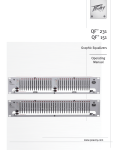
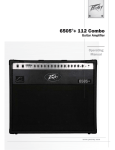
User Manual
IP™-Twelve 2-Channel Power Amplifier
Intended to alert the user to the presence of uninsulated “dangerous voltage” within the product’s
enclosure that may be of sufficient magnitude to constitute a risk of electric shock to persons.
Intended to alert the user of the presence of important operating and maintenance (servicing)
instructions in the literature accompanying the product.
CAUTION: Risk of electrical shock — DO NOT OPEN!
CAUTION: To reduce the risk of electric shock, do not remove cover. No user serviceable parts inside.
Refer servicing to qualified service personnel.
WARNING: To prevent electrical shock or fire hazard, this apparatus should not be exposed to rain or
moisture‚ and objects filled with liquids‚ such as vases‚ should not be placed on this apparatus. Before
using this apparatus‚ read the operating guide for further warnings.
Este símbolo tiene el propósito, de alertar al usuario de la presencia de “(voltaje) peligroso” sin
aislamiento dentro de la caja del producto y que puede tener una magnitud suficiente como para
constituir riesgo de descarga eléctrica.
Este símbolo tiene el propósito de alertar al usario de la presencia de instruccones importantes sobre la
operación y mantenimiento en la información que viene con el producto.
PRECAUCION: Riesgo de descarga eléctrica ¡NO ABRIR!
PRECAUCION: Para disminuír el riesgo de descarga eléctrica, no abra la cubierta. No hay piezas útiles
dentro. Deje todo mantenimiento en manos del personal técnico cualificado.
ADVERTENCIA: Para prevenir choque electrico o riesgo de incendios, este aparato no se debe exponer a
la lluvia o a la humedad. Los objetos llenos de liquidos, como los floreros, no se deben colocar encima
de este aparato. Antes de usar este aparato, lea la guia de funcionamiento para otras advertencias.
Ce symbole est utilisé dans ce manuel pour indiquer à l’utilisateur la présence d’une tension dangereuse
pouvant être d’amplitude suffisante pour constituer un risque de choc électrique.
Ce symbole est utilisé dans ce manuel pour indiquer à l’utilisateur qu’il ou qu’elle trouvera d’importantes
instructions concernant l’utilisation et l’entretien de l’appareil dans le paragraphe signalé.
ATTENTION: Risques de choc électrique — NE PAS OUVRIR!
ATTENTION: Afin de réduire le risque de choc électrique, ne pas enlever le couvercle. Il ne se trouve
à l’intérieur aucune pièce pouvant être reparée par l’utilisateur. Confiez I’entretien et la réparation de
l’appareil à un réparateur Peavey agréé.
AVIS: Dans le but de reduire les risques d'incendie ou de decharge electrique, cet appareil ne doit
pas etre expose a la pluie ou a l'humidite et aucun objet rempli de liquide, tel qu'un vase, ne doit
etre pose sur celui-ci. Avant d'utiliser de cet appareil, lisez attentivement le guide fonctionnant pour
avertissements supplémentaires.
Dieses Symbol soll den Anwender vor unisolierten gefährlichen Spannungen innerhalb des Gehäuses
warnen, die von Ausreichender Stärke sind, um einen elektrischen Schlag verursachen zu können.
Dieses Symbol soll den Benutzer auf wichtige Instruktionen in der Bedienungsanleitung aufmerksam
machen, die Handhabung und Wartung des Produkts betreffen.
VORSICHT: Risiko — Elektrischer Schlag! Nicht öffnen!
VORSICHT: Um das Risiko eines elektrischen Schlages zu vermeiden, nicht die Abdeckung enfernen.
Es befinden sich keine Teile darin, die vom Anwender repariert werden könnten. Reparaturen nur von
qualifiziertem Fachpersonal durchführen lassen.
WARNUNG: Um elektrischen Schlag oder Brandgefahr zu verhindern, sollte dieser Apparat nicht
Regen oder Feuchtigkeit ausgesetzt werden und Gegenstände mit Flüssigkeiten gefuellt, wie Vasen,
nicht auf diesen Apparat gesetzt werden. Bevor dieser Apparat verwendet wird, lesen Sie bitte den
Funktionsführer für weitere Warnungen.
2
IMPORTANT SAFETY INSTRUCTIONS
WARNING: When using electrical products, basic cautions should always be followed, including the following:
1.
Read these instructions.
2.
Keep these instructions.
3.
Heed all warnings.
4.
Follow all instructions.
5.
Do not use this apparatus near water.
6.
Clean only with a dry cloth.
7.
Do not block any of the ventilation openings. Install in accordance with manufacturer’s instructions.
8.
Do not install near any heat sources such as radiators, heat registers, stoves or other apparatus (including amplifiers) that
produce heat.
9.
Do not defeat the safety purpose of the polarized or grounding-type plug. A polarized plug has two blades with one wider than
the other. A grounding type plug has two blades and a third grounding plug. The wide blade or third prong is provided for your
safety. If the provided plug does not fit into your outlet, consult an electrician for replacement of the obsolete outlet.
10.
Protect the power cord from being walked on or pinched, particularly at plugs, convenience receptacles, and the point they exit
from the apparatus.
11.
Only use attachments/accessories provided by the manufacturer.
12.
Use only with a cart, stand, tripod, bracket, or table specified by the manufacturer, or sold with the apparatus. When a cart is
used, use caution when moving the cart/apparatus combination to avoid injury from tip-over.
13.
Unplug this apparatus during lightning storms or when unused for long periods of time.
14.
Refer all servicing to qualified service personnel. Servicing is required when the apparatus has been damaged in any way, such
as when power-supply cord or plug is damaged, liquid has been spilled or objects have fallen into the apparatus, the apparatus
has been exposed to rain or moisture, does not operate normally, or has been dropped.
15.
Never break off the ground pin. Write for our free booklet “Shock Hazard and Grounding.” Connect only to a power supply of
the type marked on the unit adjacent to the power supply cord.
16.
If this product is to be mounted in an equipment rack, rear support should be provided.
17.
Note for UK only: If the colors of the wires in the mains lead of this unit do not correspond with the terminals in your plug‚
proceed as follows:
a) The wire that is colored green and yellow must be connected to the terminal that is marked by the letter E‚ the earth symbol‚
colored green or colored green and yellow.
b) The wire that is colored blue must be connected to the terminal that is marked with the letter N or the color black.
c) The wire that is colored brown must be connected to the terminal that is marked with the letter L or the color red.
18.
This electrical apparatus should not be exposed to dripping or splashing and care should be taken not to place objects
containing liquids, such as vases, upon the apparatus.
19.
The on/off switch in this unit does not break both sides of the primary mains. Hazardous energy can be present inside the
chassis when the on/off switch is in the off position. The mains plug or appliance coupler is used as the disconnect device, the
disconnect device shall remain readily operable.
20.
Exposure to extremely high noise levels may cause a permanent hearing loss. Individuals vary considerably in susceptibility
to noise-induced hearing loss, but nearly everyone will lose some hearing if exposed to sufficiently intense noise for a sufficient
time. The U.S. Government’s Occupational Safety and Health Administration (OSHA) has specified the following permissible
noise level exposures:
Duration Per Day In Hours
8
6
4
3
2
1 1⁄2
1
1⁄2
1⁄4 or less
Sound Level dBA, Slow Response
90
92
95
97
100
102
105
110
115
According to OSHA, any exposure in excess of the above permissible limits could result in some hearing loss. Earplugs or protectors to
the ear canals or over the ears must be worn when operating this amplification system in order to prevent a permanent hearing loss, if
exposure is in excess of the limits as set forth above. To ensure against potentially dangerous exposure to high sound pressure levels, it is
recommended that all persons exposed to equipment capable of producing high sound pressure levels such as this amplification system be
protected by hearing protectors while this unit is in operation.
SAVE THESE INSTRUCTIONS!
WICHTIGE SICHERHEITSHINWEISE
ACHTUNG: Beim Einsatz von Elektrogeräten müssen u.a. grundlegende Vorsichtsmaßnahmen befolgt werden:
1.
Lesen Sie sich diese Anweisungen durch.
2.
Bewahren Sie diese Anweisungen auf.
3.
Beachten Sie alle Warnungen.
4.
Befolgen Sie alle Anweisungen.
5.
Setzen Sie dieses Gerät nicht in der Nähe von Wasser ein.
6.
Reinigen Sie es nur mit einem trockenen Tuch.
7.
Blockieren Sie keine der Lüftungsöffnungen. Führen Sie die Installation gemäß den Anweisungen des Herstellers durch.
8.
Installieren Sie das Gerät nicht neben Wärmequellen wie Heizungen, Heizgeräten, Öfen oder anderen Geräten (auch Verstärkern), die
Wärme erzeugen.
9.
Beeinträchtigen Sie nicht die Sicherheitswirkung des gepolten Steckers bzw. des Erdungssteckers. Ein gepolter Stecker weist zwei
Stifte auf, von denen einer breiter ist als der andere. Ein Erdungsstecker weist zwei Stifte und einen dritten Erdungsstift auf. Der breite
Stift bzw. der dritte Stift dient Ihrer Sicherheit. Sollte der beiliegende Stecker nicht in Ihre Steckdose passen, wenden Sie sich bitte an
einen Elektriker, um die ungeeignete Steckdose austauschen zu lassen.
10.
Schützen Sie das Netzkabel, sodass niemand darauf tritt oder es geknickt wird, insbesondere an Steckern oder Buchsen und ihren
Austrittsstellen aus dem Gerät.
11.
Verwenden Sie nur die vom Hersteller erhältlichen Zubehörgeräte oder Zubehörteile.
12.
Verwenden Sie nur einen Wagen, Stativ, Dreifuß, Träger oder Tisch, der den Angaben des Herstellers entspricht oder zusammen
mit dem Gerät verkauft wurde. Wird ein Wagen verwendet, bewegen Sie den Wagen mit dem darauf befindlichen Gerät besonders
vorsichtig, damit er nicht umkippt und möglicherweise jemand verletzt wird.
13.
Trennen Sie das Gerät während eines Gewitters oder während längerer Zeiträume, in denen es nicht benutzt wird, von der
Stromversorgung.
14.
Lassen Sie sämtliche Wartungsarbeiten von qualifizierten Kundendiensttechnikern durchführen. Eine Wartung ist erforderlich, wenn
das Gerät in irgendeiner Art beschädigt wurde, etwa wenn das Netzkabel oder der Netzstecker beschädigt wurden, Flüssigkeit
oder Gegenstände in das Gerät gelangt sind, das Gerät Regen oder Feuchtigkeit ausgesetzt wurde, nicht normal arbeitet oder
heruntergefallen ist.
15.
Der Erdungsstift darf nie entfernt werden. Auf Wunsch senden wir Ihnen gerne unsere kostenlose Broschüre „Shock Hazard and
Grounding“ (Gefahr durch elektrischen Schlag und Erdung) zu. Schließen Sie nur an die Stromversorgung der Art an, die am Gerät
neben dem Netzkabel angegeben ist.
16.
Wenn dieses Produkt in ein Geräte-Rack eingebaut werden soll, muss eine Versorgung über die Rückseite eingerichtet werden.
17.
Hinweis – Nur für Großbritannien: Sollte die Farbe der Drähte in der Netzleitung dieses Geräts nicht mit den Klemmen in Ihrem Stecker
übereinstimmen, gehen Sie folgendermaßen vor:
a) Der grün-gelbe Draht muss an die mit E (Symbol für Erde) markierte bzw. grüne oder grün-gelbe Klemme angeschlossen werden.
b) Der blaue Draht muss an die mit N markierte bzw. schwarze Klemme angeschlossen werden.
c) Der braune Draht muss an die mit L markierte bzw. rote Klemme angeschlossen werden.
18.
Dieses Gerät darf nicht ungeschützt Wassertropfen und Wasserspritzern ausgesetzt werden und es muss darauf geachtet werden, dass
keine mit Flüssigkeiten gefüllte Gegenstände, wie z. B. Blumenvasen, auf dem Gerät abgestellt werden.
19.
Der Netzschalter in dieser Einheit bricht beide Seiten von den primären Haupleitungen nicht. Gerfährliche Energie kann anwesend
innerhalb des Chassis sein, wenn her Netzschalter im ab Position ist. Die Hauptleitungen stöpseln zu oder Gerätkupplung ist benutzt,
während das Vorrichtung abschaltet, das schaltet Vorrichtung wird bleiben sogleich hantierbar ab.
20
Belastung durch extrem hohe Lärmpegel kann zu dauerhaftem Gehörverlust führen. Die Anfälligkeit für durch Lärm bedingten
Gehörverlust ist von Mensch zu Mensch verschieden, das Gehör wird jedoch bei jedem in gewissem Maße geschädigt, der über einen
bestimmten Zeitraum ausreichend starkem Lärm ausgesetzt ist. Die US-Arbeitsschutzbehörde (Occupational and Health Administration,
OSHA) hat die folgenden zulässigen Pegel für Lärmbelastung festgelegt:
Dauer pro Tag in Stunden
Geräuschpegel dBA, langsame Reaktion
8
6
4
3
2
1.5
1
.5
.25 oder weniger
90
92
95
97
100
102
105
110
115
Laut OSHA kann jede Belastung über den obenstehenden zulässigen Grenzwerten zu einem gewissen Gehörverlust führen. Sollte
die Belastung die obenstehenden Grenzwerte übersteigen, müssen beim Betrieb dieses Verstärkungssystems Ohrenstopfen oder
Schutzvorrichtungen im Gehörgang oder über den Ohren getragen werden, um einen dauerhaften Gehörverlust zu verhindern. Um sich vor
einer möglicherweise gefährlichen Belastung durch hohe Schalldruckpegel zu schützen, wird allen Personen empfohlen, die mit Geräten
arbeiten, die wie dieses Verstärkungssystem hohe Schalldruckpegel erzeugen können, beim Betrieb dieses Geräts einen Gehörschutz zu tragen.
BEWAHREN SIE DIESE SICHERHEITSHINWEISE AUF!
INSTRUCTIONS IMPORTANTES DE SECURITE
ATTENTION: L’utilisation de tout appareil électrique doit être soumise aux precautions d’usage incluant:
1.
2. 3.
4.
5.
6.
7.
8.
9.
10.
11. 12.
13.
14.
15.
16.
17.
18.
19.
20.
Lire ces instructions.
Gardez ce manuel pour de futures références.
Prétez attention aux messages de précautions de ce manuel.
Suivez ces instructions.
N’utilisez pas cette unité proche de plans d’eau.
N’utilisez qu’un tissu sec pour le nettoyage de votre unité.
N’obstruez pas les systèmes de refroidissement de votre unité et installez votre unité en fonction des instructions de ce
manuel.
Ne positionnez pas votre unité à proximité de toute source de chaleur.
Connectez toujours votre unité sur une alimentation munie de prise de terre utilisant le cordon d’alimentation fourni.
Protégez les connecteurs de votre unité et positionnez les cablages pour éviter toutes déconnexions accidentelles.
N’utilisez que des fixations approuvées par le fabriquant.
Lors de l’utilsation sur pied ou pole de support, assurez dans le cas de déplacement de l’ensemble enceinte/support de
prévenir tout basculement intempestif de celui-ci.
Il est conseillé de déconnecter du secteur votre unité en cas d’orage ou de durée prolongée sans utilisation.
Seul un technicien agréé par le fabriquant est à même de réparer/contrôler votre unité. Celle-ci doit être contrôlée si elle
a subit des dommages de manipulation, d’utilisation ou de stockage (humidité,…).
Ne déconnectez jamais la prise de terre de votre unité.
Si votre unité est destinée a etre montée en rack, des supports arriere doivent etre utilises.
Note pour les Royaumes-Unis: Si les couleurs de connecteurs du cable d’alimentation ne correspond pas au guide de la
prise secteur, procédez comme suit:
a) Le connecteur vert et jaune doit être connectrer au terminal noté E, indiquant la prise de terre ou correspondant aux
couleurs verte ou verte et jaune du guide.
b) Le connecteur Bleu doit être connectrer au terminal noté N, correspondnat à la couleur noire du guide.
c) Le connecteur marron doit être connectrer au terminal noté L, correspondant à la couleur rouge du guide.
Cet équipement électrique ne doit en aucun cas être en contact avec un quelconque liquide et aucun objet contenant un
liquide, vase ou autre ne devrait être posé sur celui-ci.
L'interrupter (on-off ) dans cette unitè ne casse pas les deux côtès du primaire principal. L'énergie hasardeuse peut
être preésente dans le châssis quand l'interrupter (on-off ) est dans le de la position. Le bouchon principal ou atelage
d'appareil est utilisé comme le débrancher l'appareil restera facilement opérable.
Une exposition à de hauts niveaux sonores peut conduire à des dommages de l’écoute irréversibles. La susceptibilité
au bruit varie considérablement d’un individu à l’autre, mais une large majorité de la population expériencera une
perte de l’écoute après une exposition à une forte puissance sonore pour une durée prolongée. L’organisme de la santé
américaine (OSHA) a produit le guide ci-dessous en rapport à la perte occasionnée:
Durée par Jour (heures)
8
6
4
3
2
1.5
1
.5
.25 ou inférieur
Niveau sonore moyen (dBA)
90
92
95
97
100
102
105
110
115
D’après les études menées par le OSHA, toute exposition au delà des limites décrites ce-dessus entrainera des pertes de l’écoute chez la
plupart des sujets. Le port de système de protection (casque, oreilette de filtrage,…) doit être observé lors de l’opération cette unité ou des
dommages irréversibles peuvent être occasionnés. Le port de ces systèmes doit être observé par toutes personnes susceptibles d’être exposées à des conditions au delà des limites décrites ci-dessus.
GARDEZ CES INSTRUCTIONS!
INSTRUCCIONES IMPORTANTES PARA SU SEGURIDAD
CUIDADO: Cuando use productos electrónicos, debe tomar precauciones básicas, incluyendo las siguientes:
1.
Lea estas instrucciones.
2.
Guarde estas instrucciones.
3.
Haga caso de todos los consejos.
4.
Siga todas las instrucciones.
5.
No usar este aparato cerca del agua.
6.
Limpiar solamente con una tela seca.
7.
No bloquear ninguna de las salidas de ventilación. Instalar de acuerdo a las instrucciones del fabricante.
8.
No instalar cerca de ninguna fuente de calor como radiadores, estufas, hornos u otros aparatos (incluyendo amplificadores) que
produzcan calor.
9.
No retire la patilla protectora del enchufe polarizado o de tipo “a Tierra”. Un enchufe polarizado tiene dos puntas, una de ellas más
ancha que la otra. Un enchufe de tipo “a Tierra” tiene dos puntas y una tercera “a Tierra”. La punta ancha (la tercera ) se proporciona
para su seguridad. Si el enchufe proporcionado no encaja en su enchufe de red, consulte a un electricista para que reemplaze su
enchufe obsoleto.
10.
Proteja el cable de alimentación para que no sea pisado o pinchado, particularmente en los enchufes, huecos, y los puntos que salen
del aparato.
11.
Usar solamente añadidos/accesorios proporcionados por el fabricante.
12.
Usar solamente un carro, pie, trípode, o soporte especificado por el fabricante, o vendido junto al aparato. Cuando se use un carro,
tenga cuidado al mover el conjunto carro/aparato para evitar que se dañe en un vuelco. No suspenda esta caja de ninguna manera.
13. Desenchufe este aparato durante tormentas o cuando no sea usado durante largos periodos de tiempo.
14. Para cualquier reparación, acuda a personal de servicio cualificado. Se requieren reparaciones cuando el aparato ha sido dañado de
alguna manera, como cuando el cable de alimentación o el enchufe se han dañado, algún líquido ha sido derramado o algún objeto ha
caído dentro del aparato, el aparato ha sido expuesto a la lluvia o la humedad, no funciona de manera normal, o ha sufrido una caída.
15. Nunca retire la patilla de Tierra.Escríbanos para obtener nuestro folleto gratuito “Shock Hazard and Grounding” (“Peligro de
Electrocución y Toma a Tierra”). Conecte el aparato sólo a una fuente de alimentación del tipo marcado al lado del cable de
alimentación.
16.
Si este producto va a ser enracado con más equipo, use algún tipo de apoyo trasero.
17. Nota para el Reino Unido solamente: Si los colores de los cables en el enchufe principal de esta unidad no corresponden con los
terminales en su enchufe‚ proceda de la siguiente manera:
a) El cable de color verde y azul debe ser conectado al terminal que está marcado con la letra E‚ el símbolo de Tierra (earth)‚ coloreado
en verde o en verde y amarillo.
b) El cable coloreado en azul debe ser conectado al terminal que está marcado con la letra N o el color negro.
c) El cable coloreado en marrón debe ser conectado al terminal que está marcado con la letra L o el color rojo.
18.
Este aparato eléctrico no debe ser sometido a ningún tipo de goteo o salpicadura y se debe tener cuidado para no poner objetos que
contengan líquidos, como vasos, sobre el aparato.
19.
El interruptor de en/lejos en esta unidad no rompe ambos lados de la red primaria. La energía peligrosa puede ser presente dentro del
chasis cuando el interruptor de en/lejos está en el de la posición. El tapón de la red o el acoplador del aparato son utilizados como el
desconecta dispositivo, el desconecta dispositivo se quedará fácilmente operable.
20.
La exposición a altos niveles de ruido puede causar una pérdida permanente en la audición. La susceptibilidad a la pérdida de
audición provocada por el ruido varía según la persona, pero casi todo el mundo perderá algo de audición si se expone a un nivel de
ruido suficientemante intenso durante un tiempo determinado. El Departamento para la Salud y para la Seguridad del Gobierno de los
Estados Unidos (OSHA) ha especificado las siguientes exposiciones al ruido permisibles:
Duración por Día en Horas Nivel de Sonido dBA, Respuesta Lenta
8
90
6
92
4
95
3
97
2
100
1.5
102
1
105
.5
110
.25 o menos
115
De acuerdo al OSHA, cualquier exposición que exceda los límites arriba indicados puede producir algún tipo de pérdida en la audición.
Protectores para los canales auditivos o tapones para los oídos deben ser usados cuando se opere con este sistema de sonido para prevenir una pérdida permanente en la audición, si la exposición excede los límites indicados más arriba. Para protegerse de una exposición a
altos niveles de sonido potencialmente peligrosa, se recomienda que todas las personas expuestas a equipamiento capaz de producir altos
niveles de presión sonora, tales como este sistema de amplificación, se encuentren protegidas por protectores auditivos mientras esta unidad esté operando.
GUARDE ESTAS INSTRUCCIONES!
Important Precautions
This symbol is used to alert the user to the
presence of important operating and maintenance
(servicing) instructions in the literature
accompanying the product.
This symbol is used to alert the user to the
presence of “dangerous voltage” within the
product enclosure that be of sufficient magnitude
to constitute a risk of electric shock to persons.
CAUTION: Risk of electrical shock - DO NOT OPEN!
CAUTION: To reduce the risk of electric shock, do not remove
cover. There are no user serviceable parts inside. Refer
servicing to qualified service personnel.
WARNING: To prevent electrical shock or fire hazard, do not
expose this appliance to rain or moisture. Before using this
appliance, read the operating guide for further warnings.
1. Save the carton and packing material even if the
equipment has arrived in good condition. Should
you ever need to ship the unit, use only the original
factory packing.
2.
Read all operating instructions in this manual and
on the back of the unit. Retain all instructions for
future reference.
3.
Follow all instructions printed on unit chassis for
proper operation.
4.
Do not spill water or other liquids into or on the unit,
or operate the unit near water, i.e., a bathtub, sink,
swimming pool, wet basement, etc.
5.
Connect only to a power supply of the type marked
on the unit adjacent to the power supply cord
connector. Damage caused by connection to
improper AC voltage is not covered by any
warranty.
6.
Power supply cords should be handled carefully.
Never walk or place equipment on power supply
cords. Periodically check cords for cuts or signs of
stress, especially at the plug and the point where
the cord exits the unit.
7.
Always operate the unit with the AC ground wire
connected to the electrical system ground. Never
break off the ground pin on the power supply cord.
For more information on grounding, write for our
free booklet Shock Hazard and Grounding.
8.
Have gain controls on amplifiers turned down during
power-up to prevent speaker damage if there are
high signal levels at the inputs.
9.
Power down and disconnect units from mains
voltage before making connections.
10.
Disconnect unit from power supply before cleaning.
Metal parts can be cleaned with a damp rag.
11.
This product should not be used near stoves, heat
registers, radiators, or other heat producing
devices.
12.
Do not block the fan intake. This product should be
located so that its position does not interfere with
its proper ventilation. It should not be placed flat
against a wall or placed in a built-in enclosure or
rack that will impede the flow of cooling air.
13.
The user should not attempt to service this
equipment. Do not remove the cover. All service
work should be performed by a qualified service
technician.
14.
Do not drive the inputs with a signal level greater
than that required to drive equipment to full
output. Peavey Electronics is not responsible for
damage to loudspeakers for any reason.
15.
Do not ground any + (“hot”) terminal. Never connect
a + (“hot”) output to ground or to another + (“hot”)
output!
16.
The user should not attempt to service this
equipment. Equipment should be serviced by
qualified service personnel when:
A.
The power supply cord or the plug has been
damaged;
B.
Anything has fallen, or been spilled into the
equipment;
C.
The equipment has been exposed to rain;
D.
The equipment does not appear to operate normally,
or exhibits a marked change in performance;
E.
The equipment has been dropped, or the enclosure
damaged.
17.
If you need set-up or operation assistance for
this product, please call Architectural Acoustics
Customer Service, Tech Service or your local
authorized dealer.
ENGLISH
IP™-Twelve Power Amplifier
Introduction
Congratulations on your purchase of a Peavey Architectural Acoustics IP-Twelve power amplifier. Please
read this manual carefully (especially the “Important Precautions” section located inside the front
cover) as it contains information vital to the safe operation of the amplifier. Also, please fill out and
return the enclosed product registration card.
IP-Twelve amplifiers are ruggedly built from high quality components and feature comprehensive
protection circuits to protect your amplifier in the real world.
If you need setup or operation assistance for this product, please call Architectural Acoustics
Customer Service Tech Service or your local authorized dealer. We appreciate suggestions that may
help us improve our products or service.
Unpacking
Inspect the amplifier during unpacking. If you find any damage, notify your dealer immediately. Only
the consignee may institute a claim with the carrier for damage incurred during shipping. Be sure
to save the carton and all packing materials. Should you ever need to ship the unit back to Peavey
Electronics, one of its service centers or the dealer, use only the original factory packaging.
Mounting
IP-Twelve amplifiers are two rack space units of 13.5" (343 mm) depth that mount in a standard 19"
rack. On all amplifiers, four front-panel mounting holes are provided. Rear-mounting ears are also
provided on all amplifiers for additional support. Distance from the back of the front-rack ear to the
center of the rear-mounting ear holes is 14 1/8" (333 mm).
Installation and
Mounting
To set the amplifier up for basic usage:
1. Rack mount the amplifier in the location where it is to be used, remembering to allow for
adequate access and cooling space. For more information, see the sections on Installation,
Mounting and Cooling Requirements.
2. Make input connections to the plugable terminal blocks on the input module. Use the
proper connections for stereo, parallel, bridged mono and grounding configuration. See the
sections on Signal Mode Configuration and Input Module Connections for more information.
3. Connect speakers to the output barrier strip. Be sure to make the correct output
connections for stereo, parallel or bridged mono configuration. See the section on Speaker
Output Connections for more information.
4. Make power connections, allowing for proper current draw. See the section on AC Mains
Circuit Size Requirements for more information.
5. Turn the front panel AC switch to ON, and bring up the back-panel gain attenuators to the
desired levels.
1
4
2
5
1
TWELVE
CH A
CH B
ACTIVE SIGNAL ACTIVE SIGNAL
TEMP
CLIP
TEMP
MODEL: IP-TWELVE
BOTTOM CABINET IP-TWELVE SPRAY BLACK
SCM: 660-180700-00
COLOUR:
TEXT AND GRAPHICS SCREENED ON CHASSIS:
PANTONE 645C GLOSSY BLUE & PEAVEY LIGHT GRAY
DATE: 12 OCTOBER 2005
1
3
Front Panel
CLIP
6
1
(1) Rack Mounting Ears
900
B REAKER
2
Two mounting holes are provided on each front mounting ear.
D ESIGNED & E NGINEERED IN U.S.A.
M ADE IN CHINA
(2) AC Power Switch/Circuit Breaker
MODEL: IP-TWELVE
BOTTOM CABINET IP-TWELVE SPRAY BLACK
SCM: 660-180700-00
COLOUR:
TEXT AND GRAPHICS SCREENED ON CHASSIS:
PANTONE 645C GLOSSY BLUE & PEAVEY LIGHT GRAY
DATE: 20 DECEMBER 2005
A power switch is on the front panel. With the switch pushed towards the up position, the
amplifier is ON.
(3) ACTIVE LED
The Active LED indicates that its channel’s output relay is closed and the channel is operational.
It lights under normal operation and remains on even when the channel is in Automatic Clip
Limiting or ACL gain reduction. These are protection features which leave the output relay closed.
If the Active LED goes off, there is no signal at the output connectors.
(4) CLIP LED
Each channel has a Clip Limiting LED. This LED illuminates at the clipping point and indicates
that internal circuitry is reducing amplifier gain to allow full power. See the section on Protection
Features for more information.
(5 ) SIGNAL LED
This LED lights when its channel produces an output signal of about 4 volts RMS or more (0.1
volt or more at the input, with 0 dB attenuation and standard x40 voltage gain). It is useful in
determining whether a signal is reaching and being amplified by the amplifier.
(6) TEMP LED
The Temp LED lights to indicate that the channel’s output relay is open, disconnecting the
speaker(s) due to an overheating condition. Once the channel temperature has returned to
safe operating conditions the LED will turn off, the channel’s output relay will close, and the
speaker(s) will be reconnected.
TWELVE
CH A
CH B
ACTIVE SIGNAL ACTIVE SIGNAL
TEMP
CLIP
TEMP
CLIP
5
6
MODEL: IP-TWELVE
BOTTOM CABINET IP-TWELVE SPRAY BLACK
SCM: 660-180700-00
COLOUR:
TEXT AND GRAPHICS SCREENED ON CHASSIS:
PANTONE 645C GLOSSY BLUE & PEAVEY LIGHT GRAY
DATE: 12 OCTOBER 2005
900
2
B REAKER
D ESIGNED & E NGINEERED IN U.S.A.
M ADE IN CHINA
MODEL: IP-TWELVE
BOTTOM CABINET IP-TWELVE SPRAY BLACK
SCM: 660-180700-00
COLOUR:
TEXT AND GRAPHICS SCREENED ON CHASSIS:
PANTONE 645C GLOSSY BLUE & PEAVEY LIGHT GRAY
DATE: 20 DECEMBER 2005
3
4
Rear Panel
2
1
(1) Input Connector
The IP-Twelve comes standard with a plug-able input connector and individual channel rotary
attenuators. Gain/input sensitivity is factory-set for an overall amplifier gain of 40. Connections at
the input connector permit the audio signal ground to be connected or lifted from the chassis ground.
See the sections on Input Module Connections and Removing or Replacing a Module for more
information.
(2) Gain Select Switch
The rear panel Gain Select Switch determines whether the amplifier has an overall gain of 40 (32 dB)
or a gain of 20 (26 dB). The out position will select x40 while the in position will select x20.
(3) Output Barrier Strip
A barrier strip is provided for connection of loudspeakers with bare wire or spade-lug connectors.
(4) IEC Power Connector
A standard IEC power connector is located at the upper left corner of the amplifier back panel. An AC
mains cord having an appropriate AC plug for the intended operating voltage is included.
(5) Fan Grille
A continuously variable speed DC fan supplies cool air into the amplifier. Do not block this air intake!
The fan operates only when the amplifier heat sinks require cooling.
(6) Circuit Breaker
A circuit breaker is on the back panel. If the circuit breaker has tripped, push it back on to return the
amplifier to operating condition. If the circuit breaker continues to trip, the amplifier needs servicing.
Do not continue to reset as severe internal damage and safety hazards could occur!
10
Operation
AC Mains Circuit Size Requirements
Power requirements for the IP-Twelve amplifier are rated at “idle”, 1/8th power (“typical” music
conditions), 1/3rd power, and maximum rated power. The maximum power current draw rating is
limited by the amplifier’s circuit breaker. Consult the specification sheet for the current that each
amplifier will demand. AC mains voltage must be the same as that indicated on the back of the
amplifier. Damage caused by connecting the amplifier to improper AC voltage is not covered by any
warranty.
NOTE: Always turn off and disconnect the amplifier from the mains voltage before making
audio connections. As an extra precaution, turn down the input attenuators while powering
up.
Cooling Requirements
IP-Twelve amplifiers use a forced-air cooling system to maintain a low, even operating temperature.
Cooling air is drawn by a continuously variable speed fan mounted on the back panel, and exhausts
through slots on the front panel. The fan will remain inactive until internal operating temperature
rises above 45C. Make sure that there is enough space around the back of the amplifier to allow air to
enter.
NOTE: If the amplifier is rack-mounted, do not use doors or covers on the front or back
without pressurizing the back of the rack. Whatever type of rack you are using, make sure
that heated air can escape freely, and that there is no resistance to the intake of cool air
through the back grill. Intake and exhaust air must flow without resistance.
Input Module Connections
The input connector accepts balanced and unbalanced audio signals. For use with an unbalanced
source, tie the inverting (-) input to ground by installing a jumper to the signal ground connection. If
the inverting input is left floating, a 6 dB loss in gain will result.
11
Operation
Signal Mode Configuration
The IP-Twelve amplifier is configured for Two-Channel (stereo), Bridged Mode, or Parallel Mode
operation at the input connector.
To send the same signal to both channels (Parallel Mode), connect the input signal to channel A
via the input connector. Run jumpers from the positive and negative terminals of channel A’s input
connector to the respective terminals of Channel B. Both channels then share channel A’s input
signal, but will operate independently. Speakers are connected as in two channel (stereo) mode.
Bridged Mode converts the amplifier into a single-channel unit with a power rating equal to the sum
of both channel’s power ratings, and at a load rating of twice that of the single channel rating. In
Bridged Mode the channels operate at opposite polarity of each other so that one channel “pushes”
and the other “pulls” equally. Signal is connected to the input connector with one jumper connecting
the positive (+) terminal of input A to the negative (-) terminal of Input B, and another jumper
connecting the negative (-) terminal of input A to the positive (+) terminal of Input B. Both channel
attenuators (A&B) are used to control signal level, and both must at the same level, preferably at 0dB
attenuation. The speakers are connected only to the designated “+” output terminals. Never ground
either side of the speaker cable when the amplifier is in Bridged mode as both sides are “hot”. If an
output patch panel is used, all connections must be isolated from each other and from the panel. For
the IP-Twelve amplifier, the minimum nominal load impedance in bridged mode is 4 ohms; this is the
equivalent of driving both channels at 2 ohms. Driving loads of less than 4 ohms may activate the
Load Fault Correction circuit and may also cause a thermal protect condition
NOTE: Regardless of operating mode, NEVER connect amplifier outputs together!
12
CONNECTIONS
Speaker Output Connections
Speakers are connected using the output barrier strip connectors. Spade lugs, ring tongues
or bare wire may be connected to the output barrier strip elements. The barrier strip can
accommodate up to a 10 gage wire per terminal. Make sure the amplifier is turned off before
you change any output connections or jumpers. Consult the Wire Gauge Chart to find a suitable
wire gauge to minimize losses of power in the speaker cables. Also, make sure that the load
impedance is not lower than that rated for the amplifier.
Signal Ground Connection
Connections at the input connector permit the audio signal ground to be connected or lifted from the
chassis ground. Whenever possible, the shield of the signal source connecting cable should connect to
the chassis ground. In some cases, however, particularly if an amplifier is being installed in an existing
system, this may result in a ground loop. If this happens, connect the shield to the signal ground only.
The chassis ground also connects to the AC ground internally. If the cable shield is connected to the
signal ground only, it will be clamped to 0.6V above or below chassis/AC ground.
13
WIRE GAUGE CHART
Cable Length
Standard Wire Gauge
Power Loss
Power Loss
Power Loss
(4Ω)
(2Ω)
(Ft.)
(AWG)
(8Ω)
5'
18 AWG
.79%
16
.5
1.0
2.0
14
.31
.62
1.24
12
.20
.40
.80
10
.125
.25
.50
10'
18 AWG
1.58%3.16%
1.58%3.16%
6.32%
16
1.0
2.0
4.0
14
.62
1.25
2.50
12
.40
.80
1.6
10
.25
.50
1.0
18 AWG
8.0%
12.6%
25.2%
16
4.0
8.0
16.0
14
2.5
5.0
10.0
12
1.603.2
6.4
10
1.0
2.0
4.0
8
.625
1.25
2.25
16 AWG
8.0%
14
5.0
10.0
20.0
123.2
6.4
12.8
10
4.0
8.0
40'
80'
16.0%32.0%
2.0
14
PROTECTION
FEATURES
The IP-Twelve incorporates protection features derived from Peavey’s extensive experience with
reliability. The amplifiers are ruggedly built from high quality components and feature comprehensive
protection circuits to protect your amplifier from those real world occurrences.
Clip Limiting
At the amplifier’s full power, or clipping point, the channel gain will automatically be reduced,
guarding the loudspeakers against damaging high power and continuous square waves that would
otherwise be produced. This is indicated by illumination of the Clip LED. Normal program transients
will not trigger Clip Limiting, only steady or excessive clipping will. Operation is virtually transparent
in use and full signal bandwidth is maintained.
Load Fault Correction
LFC (Load Fault Correction) is an innovative circuit that will instantaneously reduce channel gain to
allow the amplifier to operate at a safe level into an abnormal load. This is indicated by illumination
of the LFC LED. Moderate activation of LFC is inaudible in normal use. In addition, if extreme low
impedance or a short circuit is encountered during high signal level conditions, the amplifier’s output
relay will open.
Fade-In Protection
Fade-in operates every time the amplifier is turned on, or after a protect condition. During turn on,
the amplifier goes into protect mode and leaves the speaker load disconnected until the amplifier
determines that the operating status is normal. The Fade-in circuit attenuates the signal during
the initial turn on or protect operation. After relay release, channel gain gradually increases to the
attenuator setting to avoid unnecessary stress on the loudspeakers.
Thermal Protection
If the heat sink temperature or power transformer reaches an abnormally high temperature, the
amplifier will protect itself by disconnecting the speaker load until the amplifier returns to a normal
temperature. During this time, the Status LED will turn off, and the cooling fan will operate at
maximum speed.
Short Circuit
If an output is shorted, the LFC, speaker relay and thermal circuits will automatically protect the
amplifier. The LFC circuit senses the short circuit as an abnormal load condition and reduces the
channel gain to a safe level for the load. In extreme or severe conditions, the speaker relays will
disconnect the load and initiate a power-on start up sequence.
DC Voltage Protection
If an amplifier channel detects DC voltage or subsonic signals at its output terminals, the speaker
relay will immediately open to prevent loudspeaker damage. The Status LEDs turn off.
15
IP™-Twelve
SPECIFICATIONS
Rated Power 4 ohms bridge
1850 watts @ 1 kHz <0.1% THD
Rated Power 2 x 2 ohms
900 watts per channel @ 1 kHz <0.05% THD both channels driven
Rated Power 2 x 4 ohms
700 watts per channel @ 1 kHz <0.05% THD both channels driven
Rated Power 2 x 8 ohms
450 watts per channel @ 1 kHz <0.05% THD both channels driven
Rated Power 1 x 2 ohms
950 watts @ 1 kHz at <0.05% THD
Rated Power 1 x 4 ohms
775 watts @ 1 kHz at <0.05% THD
Rated Power 1 x 8 ohms
475 watts @ 1 kHz at <0.05% THD
Minimum Load Impedance
2 ohms
Maximum RMS Voltage Swing
73 volts
Frequency Response
10 Hz - 100 kHz; +0, -3 dB at 1 watt
Power Bandwidth
10 Hz - 50 kHz; +0, -3 dB at rated 4 ohm power
T.H.D. 2 x 2 ohms
< 0.2% @ 700 W per channel from 20 Hz to 20 kHz
T.H.D. 2 x 4 ohms
< 0.1% @ 600 W per channel from 20 Hz to 20 kHz
T.H.D. 2 x 8 ohms
< 0.1% @ 425 W per channel from 20 Hz to 20 kHz
SMPTE IMD
< 0.1% 60 Hz and 7 kHz, 250 W @ 4 ohms
Slew Rate
> 35V/us
Damping Factor (8 ohms)
> 150:1 @ 20 Hz - 1 kHz @ 8 ohms
Input CMRR
> -75 dB @ 1 kHz
Voltage Gain
x 40 (32 dB)
Input Sensitivity
1.32 volts +/- 3% for 1 kHz. 4 ohm rated power, 1.06 volts +/- 3% for 1 kHz. 2
16
IP™-Six
SPECIFICATIONS
Input Impedance
15k ohms, balanced
Hum and Noise
> -106dB, “A” weighted referenced to rated 8 ohm power
Crosstalk
> -55dB, “A” weighted referenced to rated 8 ohm power
Current Draw @ 1/8 power
1,000 watts @ 2 ohms, 685 watts @ 4 ohms, 400 @ 8 ohms
Current Draw @ 1/3 power
2,340 watts @ 2 ohms, 1,650 watts @ 4 ohms, 1,000 watts @ 8 ohms
Idle Current Draw
30 watts
Max. Current Draw
1752 watts @ 2 ohms, 1158 watts @ 4 ohms, 710 watts @ 8 ohms
Thermal Emissions (BTU/hr.)
683 @ 1/8 Power into 2 ohms
512 @ 1/8 Power into 4 ohms
307 @ 1/8 Power into 8 ohms
Cooling
Temperature dependant variable speed 80 mm DC fan
Controls
2 rear panel attenuators, gain select switch
Indicator LEDs
2 DDT (clip limiting), 2 Signal presence, 2 Active status, 2 Temp
Protection
Thermal, DC, turn-on bursts, subsonic, incorrect loads.
Connectors
Dual four pin Euro connectors, Barrier Strip speaker output, 15 amp IEC mains con-
Construction
16 ga. steel with cast front panel
Dimensions
3.5" x 19" x 13.5" + 1.25"
Packaged Weight
45 lbs. (20.4 kg)
Unit Weight
32.6 lbs. (14.8 kg)
17
Peavey Electronics Corporation • 711 A Street • Meridian, MS 39301
601-483-5376 • Fax 601-486-1678 • http://aa.peavey.com
©2007
8030