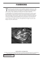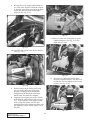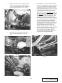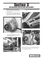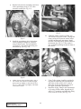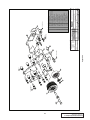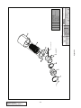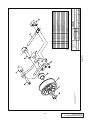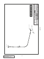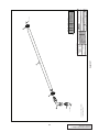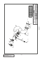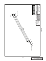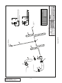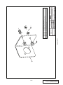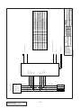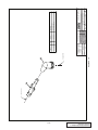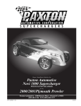
1
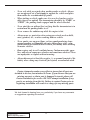
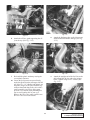
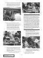
Owner’s Installation Guide for the
Paxton Automotive
Novi 1000 Supercharger
for the
2000/2001 Dodge Durango
Paxton Automotive . 1300 Beacon Place . Oxnard CA 93033
888 9-PAXTON . FAX (805) 604-1337
DP/N: 4809632 - V1.0
09/25/02
FOREWORD
T
his manual provides information on the installation, maintenance and service of the
Paxton supercharger kit expressly designed for the 2000-2001 4.7L Dodge Durango.
Contact Paxton Automotive Corporation for any additional information regarding
this kit and any of these modifications at (805) 604-1336 7:00am-3:30pm PST.
An understanding of the information contained herein will help novices, as well as experienced technicians, to correctly install and receive the greatest possible benefit from their
Paxton supercharger. When reference is made in this manual to a brand name, number, specific tool or technique, an equivalent product may be used in place of the item mentioned.
All information, illustrations and specifications contained herein are based on the latest
product information available at the time of this publication. All rights reserved to make
changes at any time without notice.
© 2002 PAXTON AUTOMOTIVE
All rights recerved. No parts of this publication may be reproduced, transmitted, transcrived, or translated into
another language in any form, by any means without written permission of Paxton Automotive.
P/N: 4809632
©2002 Paxton Automotive
All Rights Reserved, Intl. Copr. Secured
25SEP02 v1.0 Dodge Durango(4809632v1.0)
ii
TABLE OF CONTENTS
FOREWORD . . . . . . . . . . . . . . . . . . . . . . . . . . . . . . . . . . . . . . . . . . . . . . . . . . . . . . . . . . .ii
TABLE OF CONTENTS . . . . . . . . . . . . . . . . . . . . . . . . . . . . . . . . . . . . . . . . . . . . . . . . . .iii
IMPORTANT NOTES . . . . . . . . . . . . . . . . . . . . . . . . . . . . . . . . . . . . . . . . . . . . . . . . . . . .iv
RECOMMENDED TOOLS . . . . . . . . . . . . . . . . . . . . . . . . . . . . . . . . . . . . . . . . . . . . . . . .vi
PARTS LIST . . . . . . . . . . . . . . . . . . . . . . . . . . . . . . . . . . . . . . . . . . . . . . . . . . . . . . . . . . . .vii
1.0 INTRODUCTION . . . . . . . . . . . . . . . . . . . . . . . . . . . . . . . . . . . . . . . . . . . . . . . . . . . .1-1
2.0 INITIAL PREPARATION AND DISASSEMBLY . . . . . . . . . . . . . . . . . . . . . . . . . . . .2-1
3.0 SUPERCHARGER INSTALLATION AND ASSEMBLY . . . . . . . . . . . . . . . . . . . . . . .3-1
4.0 FINAL CHECK-OUT AND START-UP . . . . . . . . . . . . . . . . . . . . . . . . . . . . . . . . . . . .4-1
APPENDIX:
#1201216
#1016416
#1016623
#1015934
#1017416
#1019342
#1019343
#1020116
#1020217
#1015511
KIT, PARTS LIST . . . . . . . . . . . . . . . . . . . . . . . . . . . . . . . . . . . . . . . . . . . .A-1
ASY, S/C NOVI 1000 . . . . . . . . . . . . . . . . . . . . . . . . . . . . . . . . . . . . . . . . .A-2
ASY, S/C MOUNTING BRACKET . . . . . . . . . . . . . . . . . . . . . . . . . . . . . .A-3
ASY, AIR INTAKE . . . . . . . . . . . . . . . . . . . . . . . . . . . . . . . . . . . . . . . . . . .A-4
ASY, BELT TENSIONER . . . . . . . . . . . . . . . . . . . . . . . . . . . . . . . . . . . . . .A-5
ASY, OIL FEED . . . . . . . . . . . . . . . . . . . . . . . . . . . . . . . . . . . . . . . . . . . . .A-6
ASY, OIL DRAIN . . . . . . . . . . . . . . . . . . . . . . . . . . . . . . . . . . . . . . . . . . . .A-7
KIT, AIR DISCHARGE . . . . . . . . . . . . . . . . . . . . . . . . . . . . . . . . . . . . . . .A-8
KIT, HEATER HOSE RELOCATION . . . . . . . . . . . . . . . . . . . . . . . . . . . . .A-9
ASY, COMPRESSOR BYPASS . . . . . . . . . . . . . . . . . . . . . . . . . . . . . . . . .A-10
#1020216 ASY, CRUISE CONTROL RELOCATION . . . . . . . . . . . . . . . . . . . . . . . . .A-11
#1017718 ASY, FUEL CONTROL . . . . . . . . . . . . . . . . . . . . . . . . . . . . . . . . . . . . . . .A-12
#1020218 ASY, WASHER HOSE MODIFICATION . . . . . . . . . . . . . . . . . . . . . . . . . .A-13
iii
P/N: 4809632
©2002 Paxton Automotive
All Rights Reserved, Intl. Copr. Secured
25SEP02 v1.0 Dodge Durango(4809632v1.0)
RECOMMENDED TOOLS
FOR
INSTALLATION:
1. Metric and Standard sockets
sets
2. Metric and Standard combination
wrenches
3. Phillips and common screw drivers
4. 12” crescent wrench or 36mm
open end wrenches
5. Pliers
6. Wire cutters and wire crimping Tool
7. Hose cutters
8. 1/8” drill bit and hand drill
9. Allen wrenches
10. Small heat source
11. 3/8 Tap NPT
P/N: 4809632
©2002 Paxton Automotive
All Rights Reserved, Intl. Copr. Secured
25SEP02 v1.0 Dodge Durango(4809632v1.0)
iv
Section 1
INTRODUCTION
installation will result in a charge for any missing parts.
Before starting the installation, we suggest
your engine compartment be clean. You can
clean the engine and compartment with a pressure washer (such as those used at self serve
car washes) and a safe-for-aluminum
cleaner/degreaser. Cover the distributor with a
plastic bag to prevent water from entering.
C
ongratulations! You have purchased the
finest street Supercharger available for
the 2000-2001 4.7L Dodge Durango.
The centerpiece of this kit is the highly efficient and reliable Paxton Automotive Corp.
NOVI-1000 supercharger. A mechanically
driven (by belt) centrifugal blower (supercharger).
This kit comes with all of the parts you’ll need
for a successful installation. The operations
required have been grouped in order of
sequence. Photos and drawings accompany the
text, allowing quick orientation and parts identification.
Installation requires a selection of tools which
are listed in a table at the end of this section.
We also suggest that you obtain a Dodge shop
manual and become familiar with the details of
your cars systems. Manuals may be obtained
from your local Dodge dealer or you can order
one from Helm publications at (800)
782-4356.
For best results follow the instructions closely
and in sequence. The average installation time
for this kit is 8-10 hours. Your actual installation time will depend on skill level and working conditions. The estimate does not include
time for initial vehicle inspection, cleaning,
fine tuning or troubleshooting. Before even
picking up a wrench, read this entire manual.
We are available for technical assistance at
(805) 604-1336, 7am-3:30pm pacific time.
After reading the manual, verify that all major
assembly groups are present in the main kit
box. You should have ample space to layout
the components. As you remove a box or bag
from the main kit, note the identification label
and compare it with the parts list. Please check
the box for small parts.
Paxton makes every effort to insure that all
parts are included in the box. However, if you
discover any missing or mislabeled parts,
please contact Paxton by phone for service.
*****CAUTION*****
We do not recommend proceeding with the kit installation unless your vehicle is within normal operating
parameters.
You are undoubtedly enthusiastic about getting
started on your project, but take just a little
more time to insure that your safety is not
jeopardized. A moment’s lack of attention can
result in an accident, as can failure to observe
certain simple safety precautions. The possibility of an accident will always exist, and the
following points should not be considered a
comprehensive list of all dangers. Rather, they
are intended to make you aware of the risk and
to encourage a safety conscious approach to all
work you do on your vehicle.
We look forward to hearing from you, particularly if you
have any comments or suggestions regarding this manual at (805) 604-1336
Paxton Automotive Corporation
1300 Beacon Place
Oxnard, CA 93033
E-mail Address [email protected].
***** NOTE *****
Throughout these procedures the word “discard” is used
periodically in relationship to items that will no longer be
utilized in conjunction with the supercharger installation.
It is recommended that these items be saved for future
use should it become necessary.
*****WARNING*****
DO NOT attempt installation if any part(s) are missing
from this kit. Failure to contact Paxton prior to beginning
1-1
P/N: 4809632
©2002 Paxton Automotive
All Rights Reserved, Intl. Copr. Secured
25SEP02 v1.0 Dodge Durango(4809632v1.0)
•
Never rely solely on a jack when working under a vehicle. Always
use an approved set of jackstands to support the vehicle and place
them under the recommended lift points.
•
When jacking a vehicle, make sure it is on a level surface, preferably concrete or asphalt. The transmission should be in “PARK” or
“FIRST”, the parking brake engaged and the wheels blocked.
•
Never start the car without first verifying that the transmission is in
neutral and the parking brake is set.
•
Never remove the radiator cap while the engine is hot.
•
Always wear eye protection when using power tools such as drills,
saws, grinders, etc., or when working under a vehicle.
•
Never smoke, use an open flame, or have spark-producing items
around gasoline or flammable solvents. Always have a fire extinguisher rated for chemical and electrical fires handy when working
on motor vehicles.
•
Run engines only in well ventilated areas. Carbon monoxide, gasoline, and solvent vapors are colorless and sometimes odorless. These
can asphyxiate or explode without warning.
•
Always disconnect at least the negative (-) or ground terminal of the
battery when doing any electrical, fuel system, or underdash work.
Paxton Automotive makes every effort to insure that all parts are
included in the box, but mistakes do occur. If you discover that you are
missing any part, or that a part is damaged in transit, please call
Paxton Automotive for service. DO NOT attempt installation if any
part(s) are missing from this kit. Failure to contact Paxton prior to
beginning installation will result in a charge for any missing parts.
We look forward to hearing from you, particularly if you have any comments
or suggestions regarding this manual.
P/N: 4809632
©2002 Paxton Automotive
All Rights Reserved, Intl. Copr. Secured
25SEP02 v1.0 Dodge Durango(4809632v1.0)
1-2
Section 2
INITIAL PREPARATION AND DISASSEMBLY
d.
B
egin the initial preparation and disassembly
process by disconnecting the battery cables.
2.1
FAN AND FAN SHROUD REMOVAL
a.
b.
Remove the fan using a 36mm or a large
crescent wrench. Hitting the wrench with a
brass hammer will break it loose. The fan
unscrews counter-clockwise as viewed from
the front of the engine. (See Fig. 2-3.)
Remove the plastic panel under the front of
the vehicle by prying out the seven plastic
clips. Drain the radiator.
Remove the upper fan shroud/reservoir by
first disconnecting the three elctrical plugs
and two small hoses on the passenger side.
(See Fig 2.1.)
Fig. 2-3
2.2
AIR FILTER REMOVAL
e.
Fig. 2-1
c.
Disconnect the coolant overflow hose at the
filler cap. (See Fig. 2-2.) Make sure to
clamp or plug this hose to avoid coollant
loss. Remove the two bolts securing the
shroud using a 10mm socket. Lift up and
remove shroud.
Remove the air filter assembly (See Fig. 24). by first loosening the clamp at the throttle body, then disconnect the “S” shaped pcv
hose. (See Fig. 2-5.) Remove the nut securing rear of air box using a 10mm socket.
Lift assembly up and off the rubber mounts.
Fig. 2-4
Fig. 2-2
2-1
P/N: 4809632
©2002 Paxton Automotive
All Rights Reserved, Intl. Copr. Secured
25SEP02 v1.0 Dodge Durango(4809632v1.0)
i.
Attach the supplied coolant hoses being
careful to get the orientation correct. If necessary, hold the original metal lines in place
to see which hose goes with what fitting.
Re-use the factory spring type clamps
removed from both ends of the original
metal lines at the splice point. (See Fig.
2-8.)
Fig. 2-5
f.
g.
h.
Remove both metal coolant lines and their
mounts that run across the top of the engine.
On the passenger side of the engine, remove
the uppermost hose fitting that was connected to the coolant hose using a 3/4” wrench.
Using Teflon sealant, install the supplied 45
deg. brass fitting so it points back and up
slightly. Thread the straight hose fitting into
this using Teflon sealant. (See Figs. 2-6,
2-7.)
Fig. 2-8
j.
Detach wiring harness from the front of the
engine. (See Fig. 2-9.)
Fig. 2-6
Fig. 2-9
k.
l.
Fig. 2-7
P/N: 4809632
©2002 Paxton Automotive
All Rights Reserved, Intl. Copr. Secured
25SEP02 v1.0 Dodge Durango(4809632v1.0)
2-2
Remove the fan belt by rotating the tensioner using a 15mm wrench or socket.
Remove the four bolts securing the oil filler
neck using a 10mm deep socket. (See Fig.
2-10.)
Fig. 2-12
Fig. 2-10
p. Detach the cruise control cable at the throttle
body. (See Fig. 2-13.) Using a 10mm socket,
unbolt the cruise control actuator and seperate it from its mounting bracket.
m. Remove the three bolts securing the A/C
compressor using a 13mm and 15mm socket. Lift compressor up and let it rest on top
of the valve cover.
n. Using a 1-1/8” wrench or socket, remove the
large bolt on the front of the cylinder head.
(See Fig. 2-11.)
Fig. 2-13
q. Once you have removed the two 10mm nuts
securing the cable to the actuator, pull out
the small pin using a pair of pliers. (See Fig.
2-14.)
Fig. 2-11
o.
Trim the plastic hose that connects to the oil
filler by cutting it off just before the second
barb (approx 3/4”). Do not remove the second barb as this keeps the hose from coming
off under boost. (See Fig. 2-12.) Install the
supplied longer hose.
Fig. 2-14
2-3
P/N: 4809632
©2002 Paxton Automotive
All Rights Reserved, Intl. Copr. Secured
25SEP02 v1.0 Dodge Durango(4809632v1.0)
r.
Re-route the cruise control cable behind the
A/C lines at the firewall. Unbolt the computer from the inner fender panel using an 8mm
socket and route the cruise control cable
behind it. (See Fig. 2-15.)
Fig. 2-17
v. Bolt the oil filler neck to the plate using the
supplied hardware. (See Fig. 2-18.) Reattach the PCV hose.
Fig. 2-15
s. Re-assemble the actuator onto the new bracket.
(See Fig. 2-16.)
Fig. 2-18
w.
Bolt the A/C Compressor back in place
using the original hardware. You may need
to bend the A/C line slightly to fit in corner
of plate. (See Fig. 2-19.)
Fig. 2-16
t.
u.
Bolt the bracket to the fender panel using
the two existing holes next to the large
opening. The plug portion should point
straight down. Re-attach the cable at the
throttle body. Re-attach the computer.
Attach the rear support plate to the cylinder
head using the supplied large bolt. (See Figure
2-17) Use at least two of the supplied 6mm
bolts to align the bracket with the other
mounting holes before tightening. Make sure
the supplied O-ring is in place on the rear of
the plate.
A/C LINE
A/C COMPRESSOR
Fig. 2-19
P/N: 4809632
©2002 Paxton Automotive
All Rights Reserved, Intl. Copr. Secured
25SEP02 v1.0 Dodge Durango(4809632v1.0)
2-4
x.
Bolt the front plate to the rear plate using a
9/16”, 3/4” and a 17mm socket (See Fig.
2-20.) Check the tightness of the small idler
attached to the plate with a 9/16” socket.
z.
Fig. 2-20
y.
Install the new Accessory drive belt. (See
Fig. 2-21.) Re-install the fan. (See Fig.
2-22.)
From under the vehicle mark and drill the
oil pan in preparation for the oil drain. (See
Fig. 2-23.) On the front of the pan, measure
and mark the center. Now find the centerpoint between the pan rail. Coat a 3/16” drill
bit with grease and drill the hole. Coat the
supplied punch with anti-seize or heavy
grease and drive it in only halfway using an
air chisel with a blunt tip. Do not use a hammer. Do not go in all the way or you will
damage internal engine components. Now
you must cut off the front portion of the
hardened steel punch with either a grinder or
a cut off wheel. Continue driving the punch
in, and expand the hole until it measures
Ø9/16". Go slow with this. It will affect
your tapped hole if you go too far. Now tap
the hole using a greased 3/8 NPT tap. Go
slowly and make sure the tap goes in
straight. Stop periodically to clean and regrease the tap. Run the tap in only 2/3 of the
way and check to see that the fitting will
screw in leaving at least three threads
exposed. Clean threads thoroughly, coat fitting with Teflon sealant and install.
Fig. 2-21
Fig. 2-23
Fig. 2-22
2-5
P/N: 4809632
©2002 Paxton Automotive
All Rights Reserved, Intl. Copr. Secured
25SEP02 v1.0 Dodge Durango(4809632v1.0)
This Page Left Intentionaly Blank.
P/N: 4809632
©2002 Paxton Automotive
All Rights Reserved, Intl. Copr. Secured
25SEP02 v1.0 Dodge Durango(4809632v1.0)
2-6
Section 3
SUPERCHARGER INSTALLATION AND ASSEMBLY
3.1
d.
SUPERCHARGER INSTALLATION:
a.
b.
Test fit the supercharger in the mounting
bracket. You may need to bend the A/C lines
for a perfect fit.
Measure and cut the supplied oil drain hose
to 22-1/2” long. Secure hose to drain fitting
on supercharger using supplied clamp. (See
Fig. 3-1.)
Fasten supercharger with 6 bolts and attach
drain hose to fitting on pan. (See Figs. 3-3,
3-4.)
Fig. 3-3
Fig. 3-1
c.
Lower the supercharger into place making
sure that the oil drain hose goes over the
A/C line. (See Fig. 3-2.)
Fig. 3-4
Make sure the drain hose is routed smoothly down
hill without dips or kinks. Drain restriction may
cause supercharger failure.
Fig. 3-2
3-1
P/N: 4809632
©2002 Paxton Automotive
All Rights Reserved, Intl. Copr. Secured
25SEP02 v1.0 Dodge Durango(4809632v1.0)
e.
Bolt the belt tensioner assembly to the front
of the supercharger using a 7/32” allen
wrench or socket (See Fig. 3-5.)
Fig. 3-7
h.
Fig. 3-5
f.
Install the supercharger drive belt and tension by turning the leadscrew clockwise
using a 10mm socket. The belt should be
very tight as it will stretch after being run
and loosen up. (See Fig. 3-6)
Fig. 3-8
Fig. 3-6
g.
i.
Tighten the nut on the tensioner pulley using a
3/4” wrench. You will have to bend the uppermost a/c line up slightly to clear the belt. (See
Fig. 3-7.) Also, bend it up slightly at the radiator end until it clears.
j.
P/N: 4809632
©2002 Paxton Automotive
All Rights Reserved, Intl. Copr. Secured
25SEP02 v1.0 Dodge Durango(4809632v1.0)
Under the vehicle, near the oil filter, you
will find the oil pressure sender. Unplug and
remove using an oil pressure sender socket
available at most auto parts stores. Install
the brass TEE fitting using Teflon sealant on
the threads. (See Fig. 3-8.) The sender is
now re-installed pointing toward the front of
the vehicle.
3-2
Using Teflon sealant, install the straight fitting into the remaining port and attach one
end of the oil line using a 9/16” wrench.
Route the oil line up and across the top of
the engine toward the supercharger.
Install the 90 deg. fitting in the supercharger
oil jet using Teflon sealant. Support the jet
with a 1/2” wrench as you tighten the fitting.
Next, route the oil line. (See Fig. 3-9.)
Fig. 3-11
Fig. 3-9
k.
n.
Attach the oil line, again supporting the oil
jet at the top. (See Fig. 3-10.)
Attach the discharge tube so the injectors are
situated under the throttle linkage. (See Fig.
3-12.)
Fig. 3-12
Fig. 3-10
o.
Re-install the plastic undertray reusing the
seven plastic fasteners.
m. Locate the fuel pressure test port directly
under the dipstick on the passenger side fuel
rail. (See Fig. 3-11.) Remove the plastic cap
and place a rag over the port. Hold the rag
with one hand and depress the valve with a
small screwdriver to relieve fuel system
pressure. Use caution when prforming this
step to avoid getting fuel in your eyes.
Remove the valve core using a small screwdriver or valve core removal tool.
l.
Attach the straight end of the fuel line to the
fuel rail and the 90 deg. end to the injector
block. Tighten using a 9/16” wrench. (See
Fig. 3-13.)
Fig. 3-13
3-3
P/N: 4809632
©2002 Paxton Automotive
All Rights Reserved, Intl. Copr. Secured
25SEP02 v1.0 Dodge Durango(4809632v1.0)
q.
Route the red and black wires along with the
small four wire harness back and along the
firewall, but do not secure. The relay will be
mounted to the stud just above and to the
side of the brake booster. (See Figure 3-14.)
Fig. 3-16
*****DURANGO ONLY*****
Engine Management installation, please refer to assembly
drawing #1017718. This shows the pin locations and
correct connector on the factory ECM. Mount Paxton’s
Engine Control Unit to the cover of the power distribution
box in the engine compartment. Route the 8-wire harness across the firewall of the engine compartment to
the factory ECM. Locate the black connector on the ECM
and strip back enough of the factory tape and split loom
to allow locating the pins and colored wires in the factory
harness. Make your cuts in the harmess approximately
2” to 3” from the plug to the ECM. This allows working
room to make the connection from the Paxton supplied
Engine Management Unit to the factory ECM. (Although
Paxton supplies 8 butt connectors in the kit to make the
connections between the Engine Control Unit and the
ECM we recommend you solder the connection in place
of the supplied connectors, assuring a good connection.)
If you use the connectors, be sure to carefully crimp
them to make a good connection.
Fig. 3-14
r.) Attach the ground from the relay and the
Paxton engine management unit to the same
stud. Connect the red wire from the fueler to
terminal 87 on the relay. Route the wires
from the relay back toward the fuse box.
Using the supplied blue shrink type butt
connector, splice the green wire into the
green wire with the black stripe. (See Fig.
3-15.) This will be the trigger for the relay.
u.
v.
Route the injector harness straight across
and over the engine. Connect to the two
injectors in the discharge tube.
Re-install the fan shroud and re-connect all
electrical connections. Install the supplied
90°. rubber elbow on the washer pump discharge port nearest the dual idler pulley. Reconnect the remaining pump as stock. (See
Fig. 3-17.)
Fig. 3-15
s.
t.
Using a heat gun or lighter, apply heat until
the connector shrinks. Attach the red to the
main power terminal in the fuse box (large
black wire). (See Fig. 3-16.) Cover the wires
with the black splitloom.
Route the small four wire harness across the
firewall to the factory computer.
P/N: 4809632
©2002 Paxton Automotive
All Rights Reserved, Intl. Copr. Secured
25SEP02 v1.0 Dodge Durango(4809632v1.0)
Fig. 3-17
Install the air intake assembly. Connect the
“S” shaped hose to the small hose barb.
Connect the compressor bypass to the larger
hose barb and secure.
z. Refill the radiator with coolant.
Congratulations - you are done.
y.
3-4
Section 4
FINAL CHECK OUT AND START UP
T
his section covers pre-start checks and inspections, as well as initial start-up.
4.1 INSPECT THE FOLLOWING:
a.
b.
c.
d.
e.
4.2
Wires, harnesses and electrical connections.
Are all items properly dressed, connected
and secured? If any electrical connections
have been dis-connected, re-connect them
before you start your vehicle.
Hoses, lines and fittings. Are all items properly dressed, connected and secured?
Fasteners, brackets, and clamps. Are all
items properly installed and tightened?
Fluid levels. Is the radiator coolant and the
engine oil at their proper levels? Are there
any fluid leaks?
Belt(s). Is the serpentine drive belt (or
accessory drive and supercharger drive belts,
depending on the requirement of your vehicle) properly installed, aligned and tensioned?
Now that the work is done, it’s time to enjoy your
labor of love. Take the car out on the road
and let it flex it’s muscles, but remember, the
response and performance will now be different
from that to which you have been accustomed.
Have fun!
Perform the following:
a.
b.
c.
4.2
*****CAUTION*****
See the supercharger service manual included in your kit
for information on supercharger servicing and maintenance, belt tightening, troubleshooting, special tuning,
and warranty information.
Cycle the ignition key from “off “ to “on”
position three (3) times at fifteen (15) second intervals. Afterwards, check the entire
fuel system for any leaks.
Start the car. Verify that the oil pressure is
within the normal operating range. Listen
closely. The engine should idle and sound
the same as it did before you began the
installation. Shutdown the engine, disconnect the oil feed line from the blower.
Remove the oil jet from the blower. Blow
through the oil jet to ensure there is no
blockage or foreign matter plugging it. Reinstall oil jet and oil feed line and proceed.
Allow the engine to come to normal operating temperatures. Bleed the cooling system
and top off as necessary.
Check for the following:
a.
b.
c.
d.
Fuel leaks
Fluid leaks
Belt slippage
Throttle response
3-5
P/N: 4809632
©2002 Paxton Automotive
All Rights Reserved, Intl. Copr. Secured
25SEP02 v1.0 Dodge Durango(4809632v1.0)
This Page Left Intentionaly Blank.
P/N: 4809632
©2002 Paxton Automotive
All Rights Reserved, Intl. Copr. Secured
25SEP02 v1.0 Dodge Durango(4809632v1.0)
3-6
Appendix
A-1
P/N: 4809632
©2002 Paxton Automotive
All Rights Reserved, Intl. Copr. Secured
25SEP02 v1.0 Dodge Durango(4809632v1.0)
APPENDIX INDEX
APPENDIX NO.
1
2
3
4
5
6
7
8
9
10
11
12
13
P/N: 4809632
©2002 Paxton Automotive
All Rights Reserved, Intl. Copr. Secured
25SEP02 v1.0 Dodge Durango(4809632v1.0)
Pg.
A-3
A-4
A-5
A-6
A-7
A-8
A-9
A-10
A-11
A-12
A-13
A-14
A-15
PART NO.
DESCRIPTION
1201216
1016416
1016623
1015934
1017416
1019342
1019343
1020116
1020217
1015511
1020216
1017718
1020218
KIT CONTENTS
ASY, S/C NOVI 1000 FORWARD ROTATION
ASY, S/C MTG BRKT
ASY, AIR INTAKE
ASY, BELT TENSIONER
ASY, S/C OIL FEED HOSE
ASY, S/C OIL DRAIN HOSE
ASY, AIR DISCHARGE WITH FUEL INJECTION
ASY, HEATER HOSE RELOCATION
ASY, COMPRESSION BYPASS
ASY, CRUISE CONTROL RELOCATION
ENGINE MANAGEMENT WIRING DIAGRAM
ASY, WASHER HOSE MODIFICATION
A-2
A-3
P/N: 4809632
©2002 Paxton Automotive
All Rights Reserved, Intl. Copr. Secured
25SEP02 v1.0 Dodge Durango(4809632v1.0)
1016416
1016623
1015934
1017416
1019342
1019343
1020116
1020217
1212616
1020216
1017718
1020218
4809632
4813001
4813002
4821700
1
1
1
1
1
1
1
1
1
1
1
1
1
1
20
2
3
4
5
6
7
8
9
10
11
12
13
14
15
16
PART NO.
1
QTY.
1
ITEM NO.
Appendix 1
WRAP, NYLON TIE 5.50" LG
DECAL, GUAGE PANEL "SUPERCHARGED ENGINE"
DECAL, FUEL CAP "92 OCTANE FUEL ONLY"
BOOKLET, INSTRUCTION
ASY, WASHER HOSE MODIFICATION
ENGINE MANAGEMENT
ASY, CRUISE CONTROL RELOCATION
ASY, COMPRESSOR BYPASS
ASY, HEATER HOSE RELOCATION
ASY, AIR DISCHARGE WITH FUEL INJECTION
ASY, S/C OIL RETURN HOSE
ASY, S/C OIL SUPPLY HOSE
ASY, BELT TENSIONER
ASY, AIR INTAKE
ASY, S/C MTG BRKT
ASY, S/C NOVI 1000 FORWARD ROTATION
DESCRIPTION
Kit Contents
FINISH
NONE
WEIGHT
APPR.
21.4 LBS
UNLESS OTHERWISE SPECIFIED
CAD GENERATED DRAWING,
DIMENSIONS ARE IN INCHES
DO NOT MANUALLY UPDATE
TOLERANCES ARE: .XX± .01
DECIMALS:
.XXX±.005
DATE
APPROVALS
±1/2•
FRACTIONS:
DRAWN
G. COMPTON 1/16/01
ANGLES:
±1/16
ENGINEERING
MATERIAL
R&D
SEE PARTS LIST
SCALE:
SIZE
B
1:1
1201216
DO NOT SCALE DRAWING
DWG.
REV.
NC
SHEET 1 OF 1
KIT, 2000/2001 4.7L DODGE DURANGO
2000/2001 4.7L DODGE DURANGO
1300 BEACON PLACE OXNARD, CA 93033
TEL: (805) 604-1336 FAX: (805) 604-1337
P/N: 4809632
©2002 Paxton Automotive
All Rights Reserved, Intl. Copr. Secured
25SEP02 v1.0 Dodge Durango(4809632v1.0)
A-4
7
6
5
4
HUB TOWARD BLOWER
2
3
1
Appendix 2
FINISH
NONE
WEIGHT
APPR.
21.4 LBS
S/C ROTATION
SCALE:
SIZE
D
1:1
1016416
DO NOT SCALE DRAWING
DWG.
ASY, S/C NOVI 1000 FW ROTATION
REV.
NC
SHEET 1 OF 1
1300 BEACON PLACE OXNARD, CA 93033
TEL: (805) 604-1336 FAX: (805) 604-1337
DESCRIPTION
BLWR, NOVI 1000 REAR DISCH.
PULLEY, S/C 6 GRV 3.5
KEY, 1.25" LG x 1/8"
RET, CUP BLWR PULLEY
RET, PULLEY S/C 3/8"
SCREW, 3/8-24 x 1.00
CAP, TAMPER PROOF (GREY)
00/01 4.7L DODGE DURANGO
ITEM NO. QTY. PART NO.
1 8001007
1
1 4803342
2
2 2711503
3
1 3717250
4
1 3717204
5
1 4807201
6
1 3717225
7
UNLESS OTHERWISE SPECIFIED
CAD GENERATED DRAWING,
DIMENSIONS ARE IN INCHES
DO NOT MANUALLY UPDATE
TOLERANCES ARE: .XX± .01
DECIMALS:
.XXX±.005
DATE
APPROVALS
±1/2•
FRACTIONS:
DRAWN
A. PROCTOR 1/15/01
ANGLES:
±1/16
ENGINEERING
MATERIAL
R&D
SEE PARTS LIST
ALIGN BOLT WITH MOUNTING HOLE
A-5
P/N: 4809632
©2002 Paxton Automotive
All Rights Reserved, Intl. Copr. Secured
25SEP02 v1.0 Dodge Durango(4809632v1.0)
34 33
10
31 ? x 6
TO SUPERCHARGER
38
37
30 ?
36
30 ?
32
26 x 6
Appendix 3
41 ? TO WATER PUMP
35
28
39
42 43 x 4
TO ENGINE BLOCK
FINISH
NONE
WEIGHT
APPR.
23
G. COMPTON 2/12/01 SIZE
12.1 LBS
SCALE:
1:1
D
ITEM NO. QTY. PART NO.
1
1 4PCE010-044
2
1 4PCE010-054
3
6 2A017-878-05
4
1 4PCE017-071
5
2 4PCE017-081
6
8
7J375-044
7
2
7A375-300
8
6
7A375-250
9
1 4PCE017-101
10
1
1210518
11
1
7J500-001
12
1
7A500-600
13
1 4PCE017-051
14
1
4FR016-150
15
1
2H040-011
16
1
7A375-225
17
1 2A017-875-14
18
1
7J010-002
19
1
7C010-055
20
4
7C060-040
21
4
7J006-093
22
1
7PC024-010
23
1
7U100-063
DO NOT SCALE DRAWING
1016623
ASY, MTG BRKT
DWG.
REV.
A
SHEET 1 OF 1
1300 BEACON PLACE OXNARD, CA 93033
TEL: (805) 604-1336 FAX: (805) 604-1337
DESCRIPTION
BRKT, MTG FRONT
BRKT, MTG REAR
SPACER, PRESS FIT 7/8 x 1.50 LG
SPACER, 1.25 O.D. x .51 I.D. x 1.81 LG
SPACER, 1.25 O.D. x .39 I.D. x 1.81 LG
WASHER, 3/8 FLAT
SCREW, 3/8-16 x 3.00 LG
SCREW, 3/8-16 x 2.50 LG
COLLAR, STEP
ASY, PULLEY, IDLER DUAL
WASHER, 1/2 I.D. FLAT
SCREW, 1/2-13 x 6.00 LG
COLLAR, STEP, 950
PULLEY, IDLER SMOOTH
RET. PULLEY S/C 3/8”
SCREW, 3/8-16 x 2.25 LG
SPACER, .406 THRU
WASHER, FLAT 10.5mm I
SCREW, M10 x 1.5 x 50mm LG
SCREW, M6 x 1.0 x 40mm LG
WASHER, FLAT 6.4mm
BOLT, COMPRESSOR MTG
O-RING, BUNA-N 70
00/01 4.6L DODGE DURANGO
44 TO ENGINE BLOCK
UNLESS OTHERWISE SPECIFIED
CAD GENERATED DRAWING,
DIMENSIONS ARE IN INCHES
DO NOT MANUALLY UPDATE
TOLERANCES ARE: .XX± .01
.XXX±.005
DECIMALS:
DATE
APPROVALS
±1/2•
FRACTIONS:
DRAWN
A. PROCTOR 1/10/01
ANGLES:
±1/16
ENGINEERING G. COMPTON 1/17/01
MATERIAL
R&D
SEE PARTS LIST
L. KECK 2/12/01
24
28
27
25
P/N: 4809632
©2002 Paxton Automotive
All Rights Reserved, Intl. Copr. Secured
25SEP02 v1.0 Dodge Durango(4809632v1.0)
A-6
TO S/C ASY
9
7
8
5 4 X3
TO COMPRESSOR
BY-PASS ASY
Appendix 4
6
10
FINISH
NONE
APPR.
WEIGHT
3.8 LBS
SCALE:
SIZE
D
1:2
1015934
DO NOT SCALE DRAWING
DWG.
ASY, AIR INTAKE
00/01 4.7L DODGE
REV.
NC
SHEET 1 OF 1
1300 BEACON PLACE OXNARD, CA 93033
TEL: (805) 604-1336 FAX: (805) 604-1337
ITEM NO. QTY. PART NO. DESCRIPTION
1
1
8001997-1 HSG, FILTER MODIFIED
2
RING, FILTER RETAINER
1
8002105
3
FILTER, AIR HIGH FLOW
1
4808802
4
WASHER, #10 INT LOCK
3
2717001
5
SCREW, PAN HD, 10-24UNC-2A X .38 LG.
3
4828900
6
TUBE, AIR INTAKE
1
4810168
7
HOSE, STEP, 4.00 X 3.50
1
2735411
8
CLAMP, HOSE #56
1
1053410
9
CLAMP, HOSE #64
1
1053430
10
FTG, NIPPLE 1/2 HOSE
1
2755500
UNLESS OTHERWISE SPECIFIED
CAD GENERATED DRAWING,
DIMENSIONS ARE IN INCHES
DO NOT MANUALLY UPDATE
TOLERANCES ARE: .XX± .01
DECIMALS:
.XXX±.005
DATE
APPROVALS
±1/2•
FRACTIONS:
DRAWN
A. PROCTOR 1/10/01
ANGLES:
±1/16
ENGINEERING
MATERIAL
R&D
SEE PARTS LIST
TO CRANKCASE VENT
2
3
1
A-7
P/N: 4809632
©2002 Paxton Automotive
All Rights Reserved, Intl. Copr. Secured
25SEP02 v1.0 Dodge Durango(4809632v1.0)
1. THESE PARTS SHIP LOOSE.
NOTES: UNLESS OTHERWISE SPECIFIED
8
9
4
10
2
3
4
Appendix 5
7
6
3
1
1
11
12
PART NO.
2A046-305
7PA375-500
4FA016-150
7J500-001
7F500-025
7A250-100
7PB500-200
4PFA010-031
7A375-176
2A017-879-06
4PCE017-061
4PCE010-031
DESCRIPTION
BELT, 6 GRV
LEADSCREW
FINISH
NONE
WEIGHT
APPR.
G. COMPTON 2/12/01 SIZE
2.0 LBS
SCALE:
1:1
C
1300 BEACON PLACE OXNARD, CA 93033
TEL: (805) 604-1336 FAX: (805) 604-1337
5
1017416
DO NOT SCALE DRAWING
DWG.
ASY, BELT TENSIONER
REV.
A
SHEET 1 OF 1
2000/2001 4.7L DODGE DURANGO
IDLER, PLASTIC, 6 GRV SMOOTH
WASHER, 1/2", HEAVY
NUT, 1/2"-20UNF-2B
SCREW, FLSH, 1/4-20UNC-2A x 1.00 LG.
TENSIONER, ARBOR
RETAINER, LEADSCREW
SCREW, FLSH, 3/8-16UNC-2A x 1.75 LG.
SPACER, .875 O.D. x .390 I.D. x .800 LG
COLLAR, STEP .484 LG
TENSIONER, MTG PLATE 3/8" THK
UNLESS OTHERWISE SPECIFIED
CAD GENERATED DRAWING,
DIMENSIONS ARE IN INCHES
DO NOT MANUALLY UPDATE
TOLERANCES ARE: .XX± .01
DECIMALS:
.XXX±.005
DATE
APPROVALS
±1/2•
FRACTIONS:
DRAWN
A. PROCTOR 11/29/0
ANGLES:
±1/16
ENGINEERING G. COMPTON 1/18/01
MATERIAL
R&D
SEE PARTS LIST
L. KECK 2/12/0
1
1
1
9
10
1
8
1
5
2
2
4
7
2
3
1
1
2
6
1
QTY.
1
ITEM NO.
11
P/N: 4809632
©2002 Paxton Automotive
All Rights Reserved, Intl. Copr. Secured
25SEP02 v1.0 Dodge Durango(4809632v1.0)
A-8
5
6
TO S/C ASY
?
TO FACTORY OIL
SENDER PORT
Appendix 6
8
FACTORY OIL SENDER
FINISH
NONE
WEIGHT
APPR.
G. COMPTON 2/12/01 SIZE
.5 LBS
SCALE:
UNLESS OTHERWISE SPECIFIED
CAD GENERATED DRAWING,
DIMENSIONS ARE IN INCHES
DO NOT MANUALLY UPDATE
TOLERANCES ARE: .XX± .01
.XXX±.005
DECIMALS:
DATE
APPROVALS
±1/2•
FRACTIONS:
DRAWN
A. PROCTOR 12/01/00
ANGLES:
±1/16
ENGINEERING G. COMPTON 1/16/01
MATERIAL
R&D
SEE PARTS LIST
L. KECK 2/12/01
1:2
D
ITEM NO. QTY.
PART NO.
7U250-000-465
1
1
7P125-004
1
2
7P125-005
1
3
7P125-034
1
4
1019342
DO NOT SCALE DRAWING
DWG.
ASY, OIL FEED
000/2001 4.6L DODGE DURANGO
REV.
NC
SHEET 1 OF 1
1300 BEACON PLACE OXNARD, CA 93033
TEL: (805) 604-1336 FAX: (805) 604-1337
DESCRIPTION
HOSE, OIL SS BRAID #4
FTG, ELBOW 90° #4 AN
FTG, CONNECTOR 1/8 NPT
FTG, ADAPTER TEE 1/8 NPT
A-9
P/N: 4809632
©2002 Paxton Automotive
All Rights Reserved, Intl. Copr. Secured
25SEP02 v1.0 Dodge Durango(4809632v1.0)
3
1. SHIP THESE PARTS LOOSE.
NOTES: UNLESS OTHERWISE SPECIFIED
TO OIL PAN
2
6
Appendix 7
1
NONE
WEIGHT
APPR.
.6 LBS
UNLESS OTHERWISE SPECIFIED
CAD GENERATED DRAWING,
DIMENSIONS ARE IN INCHES
DO NOT MANUALLY UPDATE
TOLERANCES ARE: .XX± .01
DECIMALS:
.XXX±.005
DATE
APPROVALS
±1/2•
FRACTIONS:
DRAWN
A. PROCTOR 12/04/00
ANGLES:
±1/16
ENGINEERING
MATERIAL
R&D
SEE PARTS LIST
FINISH
TO S/C
SCALE:
SIZE
1:1
D
1019343
DO NOT SCALE DRAWING
DWG.
ASY, OIL DRAIN
4.7L DODGE DURANGO
REV.
NC
SHEET 1 OF 1
1300 BEACON PLACE OXNARD, CA 93033
TEL: (805) 604-1336 FAX: (805) 604-1337
ITEM NO. QTY. PART NO. DESCRIPTION
2753300-24 HOSE, OIL 1/2" I.D. x 24.00" LG
1
1
8002661
1
FTG, 90° BENT TUBE
2
8002658
1
FTG, STRT #8 AN MALE
3
8002690
1
PUNCH, OIL PAN SELF TAPPING
5
7R001-008
2
6
1
6
P/N: 4809632
©2002 Paxton Automotive
All Rights Reserved, Intl. Copr. Secured
25SEP02 v1.0 Dodge Durango(4809632v1.0)
A-10
TO STOCK
THROTTLE BODY
6
7
TO FUEL RAIL
2 REQD 4
5
6
3
TO COMPRESSOR
BY-PASS ASY
2 REQD 2
Appendix 8
6
5
1
ITEM NO. QTY.
1
1
2
2
1
3
2
4
2
5
4
6
1
7
PART NO.
4PCE012-031
8F060-042
1016044
7PA250-275
7PS300-200
7R002-048
1018913
FINISH
NONE
WEIGHT
APPR.
1020116
DO NOT SCALE DRAWING
DWG.
REV.
A
SHEET 1 OF 1
ASY, AIR DISCHARGE w/FUEL ENRICHMENT
00/01 4.7L DODGE DURANGO
1300 BEACON PLACE OXNARD, CA 93033
TEL: (805) 604-1336 FAX: (805) 604-1337
DESCRIPTION
TUBE, AIR DISCHARGE
INJECTOR, FUEL 42LB
ASY, FUEL LOG
SCREW, SHLD SOC HD, 1/4-20UNC-2A
HOSE, TURBO, 3.00 O.D. X 2.00 LG.
CLAMP, HOSE #48
ASY, FUEL LINE
G. COMPTON 2/12/01 SIZE
D
2.6 LBS
SCALE: 1:1.5
UNLESS OTHERWISE SPECIFIED
CAD GENERATED DRAWING,
DIMENSIONS ARE IN INCHES
DO NOT MANUALLY UPDATE
TOLERANCES ARE: .XX± .01
DECIMALS:
.XXX±.005
DATE
APPROVALS
±1/2•
FRACTIONS:
DRAWN
A. PROCTOR 1/10/01
ANGLES:
±1/16
ENGINEERING G. COMPTON 2/12/01
MATERIAL
R&D
SEE PARTS LIST
L. KECK
6
TO S/C ASY
A-11
P/N: 4809632
©2002 Paxton Automotive
All Rights Reserved, Intl. Copr. Secured
25SEP02 v1.0 Dodge Durango(4809632v1.0)
TO UPPERMOST FITTING ON
PASSENGER SIDE OF ENGINE
4
3
5
Appendix 9
1
FINISH
NONE
WEIGHT
APPR.
1.8 LBS
2
SCALE:
SIZE
D
1:1
1020217
DO NOT SCALE DRAWING
DWG.
ASY, HEATER HOSE RELOCATION
REV.
NC
SHEET 1 OF 1
2000/2001 4.7L DODGE DURANGO
1300 BEACON PLACE OXNARD, CA 93033
TEL: (805) 604-1336 FAX: (805) 604-1337
ITEM NO. QTY. PART NO. DESCRIPTION
3863110-42 HOSE, HEATER 5/8 x 42.00" LG
2
1
8001541
COUPLING, INLINE HOSE
2
2
8002933
FTG, W/H 5/8" x 3/8"
1
3
3886401
FTG, 45^ STREET ELBOW
1
4
1048960
CLAMP, HOSE #10
2
5
RE-USE FACTORY SPRING
UNLESS OTHERWISE SPECIFIED
CAD GENERATED DRAWING,
DIMENSIONS ARE IN INCHES
DO NOT MANUALLY UPDATE
TOLERANCES ARE: .XX± .01
DECIMALS:
.XXX±.005
DATE
APPROVALS
±1/2•
FRACTIONS:
DRAWN
A. PROCTOR 12/01/00
ANGLES:
±1/16
ENGINEERING
MATERIAL
R&D
SEE PARTS LIST
TO FACTORY
HEATER HOSE
P/N: 4809632
©2002 Paxton Automotive
All Rights Reserved, Intl. Copr. Secured
25SEP02 v1.0 Dodge Durango(4809632v1.0)
A-12
4
11
TO AIR DISCHARGE ASY
TO AIR INTAKE ASY
4
4
10
1
4
12
9
8
Appendix 10
14
TO VACUUM PORT
ON INTAKE MANIFOLD
ITEM NO.
1
4
8
9
10
11
12
13
14
FINISH
NONE
WEIGHT
APPR.
4.3 LBS
2
6.00 ±.06
SCALE:
SIZE
5:8
D
PART NO.
8D001-001
7R002-016
7P156-082
7P157-219
7U133-100-10
7U133-100-09
7U030-046X30-2
7U030-046X36
7U030-046X15
1015511
DO NOT SCALE DRAWING
DWG. NO.
ASY, COMPRESSOR BY-PASS
00/01 4.7L DODGE DURANGO/RT
REV.
NC
SHEET 1 OF 1
1300 BEACON PLACE OXNARD, CA 93033
TEL: (805) 604-1336 FAX: (805) 604-1337
DESCRIPTION
VALVE, BY-PASS
HOSE, CLAMP #16
TEE, VACUUM, 5/32
ADAPTER, VACUUM, 5/32 X 7/32
ITEM 2 MODIFICATION DETAIL
QTY.
1
4
1
1
1
1
1
1
1
TO VACUUM PORT
ON FUELER
3
ITEM 3 MODIFICATION DETAIL
UNLESS OTHERWISE SPECIFIED
CAD GENERATED DRAWING,
DIMENSIONS ARE IN INCHES
DO NOT MANUALLY UPDATE
TOLERANCES ARE: .XX± .01
DECIMALS:
.XXX±.005
DATE
APPROVALS
±1/2•
FRACTIONS:
DRAWN
G. COMPTON 4/18/01
ANGLES:
±1/16
ENGINEERING
MATERIAL
R&D
SEE PARTS LIST
13
4.00 ±.06
4.00 ±.06
5.00 ±.06
A-13
P/N: 4809632
©2002 Paxton Automotive
All Rights Reserved, Intl. Copr. Secured
25SEP02 v1.0 Dodge Durango(4809632v1.0)
1
4 2x
Appendix 11
2
2
2
4
2
3
4
SCREW, HXHD, 1/4-20UNC-2A X .75 LG., STEEL GR5
NUT, HXHD, 1/4-20UNC-2B STEEL GR5 WITH NYLOK
WASHER, 1/4 FLAT SAE
4PCE010-060
7A250-074
7F250-021
7J250-022
FINISH
NONE
WEIGHT
APPR.
1300 BEACON PLACE OXNARD, CA 93033
TEL: (805) 604-1336 FAX: (805) 604-1337
G. COMPTON 2/12/01 SIZE
C
.3 LBS
SCALE: 1.5:1
1020216
DO NOT SCALE DRAWING
DWG.
ASY, CRUISE CONTROL RELOCATION
REV.
A
SHEET 1 OF 1
2000/2001 4.7L DODGE DURANGO
DESCRIPTION
BRKT, MTG, CRUISE CONTROL
PART NO.
4 2x
UNLESS OTHERWISE SPECIFIED
CAD GENERATED DRAWING,
DIMENSIONS ARE IN INCHES
DO NOT MANUALLY UPDATE
TOLERANCES ARE: .XX± .01
DECIMALS:
.XXX±.005
DATE
APPROVALS
±1/2•
FRACTIONS:
DRAWN
A. PROCTOR 8/14/01
ANGLES:
±1/16
ENGINEERING G. COMPTON 10/4/01
MATERIAL
R&D
SEE PARTS LIST
2/12/01
L. KECK
1
QTY.
1
ITEM NO.
3
PCM CONNECTOR (BLACK)
PIN #26 O2 SENSOR
PIN #24 O2 SENSOR
PIN #18 CAM SENSOR
LIGHT GREEN/RED
LIGHT GREEN/RED
BLACK/GREEN
BLACK/GREEN
TAN/YELLOW
TAN/YELLOW
PIN #8 CRANK SENSOR
GRAY/BLACK
GRAY/BLACK
P/N: 4809632
©2002 Paxton Automotive
All Rights Reserved, Intl. Copr. Secured
25SEP02 v1.0 Dodge Durango(4809632v1.0)
A-14
O2 SENSOR
O2 SENSOR
CAMSENSOR
CRANK SENSOR
LIGHT/ GREEN
DARK/GREEN
TAN
GRAY
GRAY/BLACK
TAN/YELLOW
BLACK/GREEN
LIGHT GREEN/RED
O2 SENSOR OUT
O2 SENSOR OUT
CAM OUT
CRANK OUT
CRANK IN
CAM IN
O2 SENSOR IN
O2 SENSOR IN
PAXTON FUELER & IGNITION BOX
BLACK
RED
Appendix 12
UNLESS OTHERWISE SPECIFIED
THIS DRAWING IS THE PROPERTY DIMENSIONS ARE IN INCHES
OF PAXTON AUTOMOTIVE CORP
TOLERANCES ARE: .XX± .01
AND IS FURNISHED ON THE
DECIMALS:
.XXX±.005
CONDITION THAT IT IS NOT TO BE
±1/2•
FRACTIONS:
REPRODUCED, COPIED OR USED
ANGLES:
±1/16
DIRECTLY OR INDIRECTLY IN THE MATERIAL
MAKING OF DRAWINGS, PRINTS,
SEE
PARTS
LIST
APPARATUS OR PARTS THEREOF
WITHOUT WRITTEN
FINISH
AUTHORIZATION.
NONE
TO VACUUM/ BOOST
TO GROUND
DESCRIPTION
WEIGHT
APPR.
R&D
21.4 LBS
DATE
6/07/02
SCALE:
SIZE
A
1017718
DO NOT SCALE
DWG.
REV.
NC
SHEET 1 OF 1
ENGINE MANAGEMENT WIRING DIAGRAM
FOR 4.7 DODGE DURANGO / RAM 1500
1300 BEACON PLACE OXNARD, CA 93033
TEL: (805) 604-1336 FAX: (805) 604-1337
ENGINE MANAGEMENT UNIT 00-01 PROGR.
10-24 x 1/2 BUTTONHD CAP
10-24 NYLOK NUT
#10 x .50 LG. HX FLG SCREW, SHMTL,
HARNESS, ENGINE MANAGEMENT POWER
12-10GA FEMALE SLIDE
SOLDERLESS CONNECTOR
WIRE TAP INLINE
1/2" PLASTIC WIRE LOOM
CAD GENERATED DRAWING,
DO NOT MANUALLY UPDATE
QTY
1
2
2
2
1
2
8
1
8'
APPROVALS
DRAWN
LK
ENGINEERING
PART NO.
4PCE160-010
7C010-052
7F010-024
7E010-051
5A001-040
5W001-040
5W001-012
5W001-001
5W001-021
TO SUPPLIED RELAY TERMINAL 87 ON RELAY
1
2
3
4
5
6
7
8
9
ITEM NO.
TO SUPPLIED INJECTORS
A-15
P/N: 4809632
©2002 Paxton Automotive
All Rights Reserved, Intl. Copr. Secured
25SEP02 v1.0 Dodge Durango(4809632v1.0)
TO FACTORY HOSE
2
Appendix 13
QTY.
1
1
ITEM NO.
1
2
PART NO.
7P157-219
7U125-010
FINISH
NONE
WEIGHT
APPR.
G. COMPTON 2/12/01 SIZE
.01 LBS
SCALE:
B
2:1
1020218
DO NOT SCALE DRAWING
DWG.
ASY, WASHER HOSE MODIFICATION
REV.
A
SHEET 1 OF 1
1300 BEACON PLACE OXNARD, CA 93033
TEL: (805) 604-1336 FAX: (805) 604-1337
00/01 4.7L DODGE DURANGO
FTG, ADAPTER, 5/32-7/32
FTG, WASHER PUMP
DESCRIPTION
UNLESS OTHERWISE SPECIFIED
CAD GENERATED DRAWING,
DIMENSIONS ARE IN INCHES
DO NOT MANUALLY UPDATE
TOLERANCES ARE: .XX± .01
DECIMALS:
.XXX±.005
DATE
APPROVALS
±1/2•
FRACTIONS:
DRAWN
G. COMPTON 1/16/01
ANGLES:
±1/16
ENGINEERING G. COMPTON 1/16/01
MATERIAL
R&D
SEE PARTS LIST
2/12/01
L. KECK
TO WASHER PUMP
1
1300 Beacon Place, Oxnard CA 93033 • Tel: 888 9-PAXTON • www.paxtonautomotive.com
P/N: 4809632
©2002 Paxton Automotive
All Rights Reserved, Intl. Copr. Secured
25SEP02 v1.0 Dodge Durango(4809632v1.0)
A-16