1
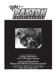
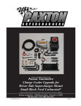
PaxFreehandBW/Lg-1.eps—11/11/03
Owner’s Installation Guide for the
Paxton Automotive
Novi 1200 Supercharger
for the
Universal Small
Block Ford-Carbureted System*
* Legal in California only for racing vehicles which may never be used upon a highway.
Paxton Automotive, 1300 Beacon Place, Oxnard CA 93033 • 805 604-1336
www.paxtonautomotive.com • M-F 8:00 AM - 4:30 PM PST
P/N: 4PFX020-010
©2004 Paxton Automotive Corp.
All Rights Reserved, Intl. Copr. Secured
28JUL04 v1.2(Univ.SBF Carb-4PFX v1.2)
FOREWORD
This manual provides information on the installation, maintenance and service of the Paxton
supercharger kit designed for small block Ford carbureted engines. Contact Paxton Automotive Corporation for any additional information regarding this kit and any of these modifications at (805) 604-1336 7:00am-3:30pm PST.
An understanding of the information contained herein will help novices, as well as experienced technicians, to correctly install and receive the greatest possible benefit from their
Paxton supercharger. When reference is made in this manual to a brand name, number, specific tool or technique, an equivalent product may be used in place of the item mentioned. All
information, illustrations and specifications contained herein are based on the latest product
information available at the time of this publication. All rights reserved to make changes at
any time without notice.
*** NOTE ***
This supercharger kit is not compatible with air conditioning as the A/C pulley is not
present on the supplied crank pulley.
NOTES
• The crank pulley supplied with this kit is designed to
accomodate the stock 1965 Mustang water pump*,
alternator and power steering. Vehicles with different
accessories may need custom spacing or elimination
of some accessories.
o be replaced).
• Distributor clearance to the carburetor enclosure
is minimal. Distributors must have a small diameter cap in order to fit. Additionally, tall distributors
such as an MSD PN 8354 installed on a 351W
contact the front of the carburetor enclosure and
should be replaced with an MSD PN 8578 (or
equivalent).
© 2004 PAXTON AUTOMOTIVE
All rights reserved. No part of this publication may be reproduced, transmitted, transcribed, or
translated into another language in any form, by any means without written permission
of Paxton Automotive.
P/N: 4PFX020-010
©2004 Paxton Automotive Corp.
All Rights Reserved, Intl. Copr. Secured
28JUL04 v1.2(Univ.SBF Carb-4PFX v1.2)
ii
TABLE OF CONTENTS
FOREWORD/NOTES .................................................................................................. ii
TABLE OF CONTENTS ................................................................................................ iii
TOOL & SUPPLY REQUIREMENTS ........................................................................... iv
PARTS LIST ................................................................................................................. v
1.
INTRODUCTION ................................................................................................................ 1-1
2.
PREPARATION/REMOVAL ............................................................................................... 2-1
3.
OIL FEED INSTALLATION ............................................................................................... 3-1
4.
OIL DRAIN INSTALLATION ............................................................................................ 4-1
5.
FUEL PUMP BOOST REFERENCE .................................................................................. 5-1
6.
MOUNTING BRACKET/SUPERCHARGER INSTALLATION ..................................... 6-1
7.
CARBURETOR ENCLOSURE INSTALLATION ............................................................. 7-1
8.
AIR DUCTING INSTALLATION ....................................................................................... 8-1
9.
CRANK PULLEY AND SUPERCHARGER DRIVE PULLEY INSTALLATION ........... 9-1
10.
FINAL REASSEMBLY AND CHECK ............................................................................... 10-1
iii
P/N: 4PFX020-010
©2004 Paxton Automotive Corp.
All Rights Reserved, Intl. Copr. Secured
28JUL04 v1.2(Univ.SBF Carb-4PFX v1.2)
Universal Small Block Ford
Carbureted System
Installation Instructions
PLEASE READ CAREFULLY
This kit should only be installed by qualified mechanics. It is imperative that the correct
air/fuel mixture be maintained at all times. This Kit is to be supplied to competent
engine tuners for their completion by the addition of, and tuning of, an appropriate
carburetor unit.
This product is intended for use on healthy, well maintained engines. Installation on a
worn-out or damaged engine is not recommended and may result in failure of the engine.
Paxton Automotive is not responsible for engine damage. Installation on new
engines will not harm or adversely affect the break-in period so long as factory breakin procedures are followed.
For best performance and continued durability, please take note of the following key
points:
1. Use only premium grade fuel 91 octane or higher (R+M/2).
2. The engine must have stock or lower than stock compression ratio.
3. If the engine has been modified in any way, check with Paxton prior to using this product.
4. Always listen for any sign of detonation (pinging) and discontinue hard use (no boost) until
problem is resolved.
5. Perform an oil and filter change upon completion of this installation and prior to operating the
vehicle. Thereafter, always use a high grade SF rated engine oil or a high quality synthetic,
and change the oil and filter every 3000 miles.
6. Before beginning installation, replace all spark plugs with one to two step colder heat range
and reset timing to no more than 26° total or install a boost retard ignition. (Always follow the
procedures indicated in the factory repair manual.)
TOOL AND SUPPLY REQUIREMENTS:
• Factory Repair Manual
• 3/8" Drive and Socket Set: SAE and Metric
• 1/2" Drive and Socket Set: SAE and Metric
• Open End Wrenches: SAE and Metric
• Center Punch
• SF Rated Quality Engine Oil
• Loctite Sealer #RC-609
P/N: 4PFX020-010
©2004 Paxton Automotive Corp.
All Rights Reserved, Intl. Copr. Secured
28JUL04 v1.2(Univ.SBF Carb-4PFX v1.2)
iv
• Oil Filter, and Wrench
• Heavy Grease
• Silicone Sealer
• Teflon Paste Sealant
• TAP, 3/8-18 NPT
1964-1968 Mustang Small Block
Ford, Passenger Side Carbureted
Part No. 1001839
PARTS LIST
SUPERCHARGERS & FUEL SYSTEMS
IMPORTANT: Before beginning installation, verify that all parts are included in the kit. Report any shortages
or damaged parts immediately.
Part Number
1016116
2A038-370
2A048-575
Description
Quantity
S/C ASSY, NOVI 1200, CW, CRV
S/C PULLEY Ø3.70 8-GROOVE
BELT, 57.5"
1
1
1
4PFX118-021
4FA111-042
4PFX017-933
4PFX018-021
7A375-151
7A375-250
7K375-040
S/C DRIVE ASSY 3 OR 4 BOLT
S/C BELT TENSIONER ASSY, H.O.
SPACER, SBF C/P
CRANK PULLEY, SBF CARB
3/8-16 X 1.5 HXHD GR8
3/8-16 X GR8 HX
3/8 AN960 FLAT WASHER, PLATED
1
1
1
1
4
3
4
8PM205-012
8PM105-012
8PM003-051
7P500-087
7A312-078
7P187-102
7P187-103
7P375-104
7A312-252
7F312-024
7J312-000
7U100-003
7U100-008
8M001-018
7C011-050
7U100-020
8M001-017
7P250-084
CARB.ENCL ASSY, SBF CARB
ENCL. STD. MACH. ASSY
CARB CVR, PAXTON
PLUG BTNHD, AN-8 WITH 0-RING, BLK
5/16-18 X 3/4 HOSE
FITTING, -3 TO 1/4 HOSE
PLUG, -3 BUTTONHEAD WITH O-RING
PLUG, OIL HOLE
5/16 STUD
6/16-24 JAM NUT
5/16 FLAT WASHER-SAE
O-RING, -3
O-RING, -8
GASKET, 90MM THROTTLE BODY
10-32 PLUG SCREW
10-32 GASKET
HOLLEY 4-BARREL BASE GASKET
1/4 NPT X 1/2 X 90 BARB
1
1
1
3
16
3
1
3
4
4
4
4
3
1
1
1
2
1
8M110-600
2A017-031
4PFX017-200
7A375-075
7C010-052
7C010-077
7C010-187
7C010-188
7C011-075
7F010-001
7F010-033
7J010-001
7J010-687
7J375-044
8M010-010
8M010-040
8M010-050
8M010-070
8M010-080
8M010-090
8M010-140
8M010-600
ASSY, THROTTLE 64-68 MUSTANG
SPACER, THROTTLE ENCL. .313 ID
SPACER, 64-68 MUSTANG THROTTLE ARM, 2”
3/8-16 X 3/4 GR5 HXHD ZINC
10-24 X 1/2 SS BHCS
10-24 X 3/4 SS BHCS
3/16 ROD END RH WITH NUT
3/16 ROD END LH WITH NUT
10-32 SCREW
NUT, THROTTLE
10-32 NUT
#10 FLAT WASHER
WASHER, THROTTLE
3/8 SAE WASHER, PLTD
BRACKET, IDLE
THROTTLE ARM INNER
THROTTLE SHAFT
RETAINER, SPRING ENCL.
RETAINER, SPRING THROTTLE
SPRING, THROTTLE ENCL.
SHAFT, 5/16 HEX
SHAFT, THROTTLE 64-66 MUSTANG
1
1
1
1
4
5
2
2
1
1
1
8
1
2
1
2
1
1
1
1
1
1
4PFX110-044
4PFX010-034
4PFX010-044
2A017-101-400
2A017-101-121
7A375-500
7A375-575
7A375-126
7A437-550
7K375-040
MTG PLATE ASSY, PASSENGER SIDE
PRIMARY MTG PLATE
S/C MTG PLATE
SPACER, SBF MTG PLATE
SPACER, FORD ALTERNATOR
3/8-16 X 5” HXHD GR8
3/8-16 X 5.75 HXHD GR8 PLT
3/8-16 X 1.25 HXHD GR8 PLT
7/16”-14 X 5-1/2” HXHD
3/8 AN960 FLAT WASHER, PLATED
1
1
1
4
1
3
2
6
1
11
4PFX130-026
7P125-004
7P250-034
7P250-250
7U250-090-240
7U100-055
OIL FEED LINE ASSY, SBF CARB
1/8 NPT 90° X -4 JIC FTG
1/4 NPT X 1/4 NPT STRT T
1/4” NPT STR X -4 JIC FTG
OIL FEED HOSE, 24” -4 X 90°
TIE WRAP, 6” NYLON
1
1
1
1
1
2
Part Number
Description
Quantity
4PFX130-036
7P375-017
7R001-008
7U030-036
OIL DRAIN ASSY, SBF CARB
3/8 NPT X 1/2 BEADED HOSE BARB
#8 STNLS HOSE CLAMP
1/2” OIL DRAIN HOSE
1
1
2
1.5
4PFX112-021
4PFX012-021
7P750-100
7PS300-275
7PS350-300
7R002-016
7R002-044
7R002-048
7R002-056
7U030-046
7U034-016
8D001-001
8M003-041
8H040-075
AIR DISCHARGE ASSY, SBF CARB
MACH, DISCH TUBE SBF CARB
3/4 NPT X 1” HOSE FITTING
REDUCER, 3.00 - 2.75
REDUCER, BLK 3.5 - 3 X 2LG, MOD
#16 GOLDSEAL, HOSE CLAMP
#44 SAE TYPE F SS HOSE CLAMP
#48 SAE TYPE F SS HOSE CLAMP
#56 SAE TYPE F SS HOSE CLAMP
5/32” VACUUM LINE
1” GS HOSE
STD COMP BYPASS VALVE
MACHINE, 3.5 FLANGE
1" AIR FILTER
1
1
1
1
1
2
1
2
1
2
0.25
1
1
1
4PFX101-001
7P125-016
7P250-043
7P250-047
7P250-141
7P500-083
7P500-084
7P500-085
7P500-086
7P500-087
7P500-089
7P500-377
7R001-006
7U030-046
7U032-016
7U100-008
8H040-020
8F001-120
FUEL ASSEMBLY, SBF CARB
1/8 NPT PLUG
1/4 NPT X 5/16” BARB
1/4 NPT TO 3/8” BARB 90°
-6 HOSE END, 90°
AN -8 HOSE END, STRAIGHT
MALE TEE -8, -6, -6
FITTING, -8 BULKHEAD WITH O-RING
120° -8 TO 1/2” BARB
PLUG, AN-8 O-RING PORT
FITTING, -8 BULKHEAD NUT, BLK
AN-8 MALE SHORT -6 MALE STD
#6 STNLS HOSE CLAMP
5/32” VACUUM LINE
3/8” EFI FUEL HOSE HI-PSR
O-RING, -8
FUEL FILTER, INLINE 3/8”
FUEL PUMP, SBF CARB 120 GPH, 6 PSI
1
1
1
1
1
1
1
1
1
1
1
1
4
4.5
2.5
3
1
1
4PFX020-010
INSTALLATION INSTRUCTIONS, SBF CARB
1
AIR FILTER, 3.5” FLG X 5.1L OFFSET
1
8H040-350
008575
S/C STRT INFO PKG ASSY PAXTON
1
8M110-100
HOLLEY 4150 FLOAT BOWL LINE ASSY
1
8M110-120
DEMO FLOAT BOWL LINE ASSY W/FTGS
1
ADDITIONAL PARTS NEEDED FOR COMPLETE INSTALLATION
1) HOLLEY 4150 OR DEMON STYLE MECHANICAL SECONDARY
CARBURETOR
v
P/N: 4PFX020-010
©2004 Paxton Automotive Corp.
All Rights Reserved, Intl. Copr. Secured
28JUL04 v1.2(Univ.SBF Carb-4PFX v1.2)
1964-1968 Mustang Small Block
Ford, Driver Side Carbureted
Part No. 1001840
PARTS LIST
SUPERCHARGERS & FUEL SYSTEMS
IMPORTANT: Before beginning installation, verify that all parts are included in the kit. Report any shortages
or damaged parts immediately.
Part Number
1016117
2A038-370
2A048-575
Description
Quantity
S/C ASSY, NOVI 1200, CW, STR
S/C PULLEY Ø3.70 8-GROOVE
BELT, 57.5"
1
1
1
4PFX118-021
4FA111-042
4PFX017-933
4PFX018-021
7A375-151
7A375-250
7K375-040
S/C DRIVE ASSY 3 OR 4 BOLT
S/C BELT TENSIONER ASSY, H.O.
SPACER, SBF C/P
CRANK PULLEY, SBF CARB
3/8-16 x 1.5 HXHD GR8
3/8-16 x GR8 HX
3/8 AN960 FLAT WASHER, PLATED
1
1
1
1
4
3
4
8PM205-012
8PM105-012
8PM003-051
7P500-087
7A312-078
7P187-102
7P187-103
7P375-104
7A312-252
7F312-024
7J312-000
7U100-003
7U100-008
8M001-018
7C011-050
7U100-020
8M001-017
7P250-084
CARB.ENCL ASSY, SBF CARB
ENCL. STD. MACH. ASSY
CARB CVR, PAXTON
PLUG BTNHD, AN-8 WITH 0-RING, BLK
5/16-18 x 3/4 HOSE
FITTING, -3 TO 1/4 HOSE
PLUG, -3 BUTTONHEAD WITH O-RING
PLUG, OIL HOLE
5/16 STUD
6/16-24 JAM NUT
5/16 FLAT WASHER-SAE
O-RING, -3
O-RING, -8
GASKET, 90MM THROTTLE BODY
10-32 PLUG SCREW
10-32 GASKET
HOLLEY 4-BARREL BASE GASKET
1/4 NPT x 1/2 x 90 BARB
1
1
1
3
16
3
1
3
4
4
4
4
3
1
1
1
2
1
8M110-600
ASSY, THROTTLE 64-68 MUSTANG
2A017-031
SPACER, THROTTLE ENCL. .313 ID
4PFX017-200SPACER, 64-68 MUSTANG THROTTLE ARM, 2”
7A375-075
3/8-16 x 3/4 GR5 HXHD ZINC
7C010-052
10-24 x 1/2 SS BHCS
7C010-077
10-24 x 3/4 SS BHCS
7C010-187
3/16 ROD END RH WITH NUT
7C010-188
3/16 ROD END LH WITH NUT
7C011-075
10-32 SCREW
7F010-001
NUT, THROTTLE
7F010-033
10-32 NUT
7J010-001
#10 FLAT WASHER
7J010-687
WASHER, THROTTLE
7J375-044
3/8 SAE WASHER, PLTD
8M010-010
BRACKET, IDLE
8M010-040
THROTTLE ARM INNER
8M010-050
THROTTLE SHAFT
8M010-070
RETAINER, SPRING ENCL.
8M010-080
RETAINER, SPRING THROTTLE
8M010-090
SPRING, THROTTLE ENCL.
8M010-140
SHAFT, 5/16 HEX
8M010-600
SHAFT, THROTTLE 64-66 MUSTANG
1
1
1
1
4
5
2
2
1
1
1
8
1
2
1
2
1
1
1
1
1
1
4PFX110-034
4PFX010-034
4PFX010-044
2A017-101-475
7A375-650
7A375-575
7A375-126
7A437-650
7K375-040
MTG PLATE ASSY, DRIVER SIDE
PRIMARY MTG PLATE
S/C MTG PLATE
SPACER, SBF MTG PLATE
3/8-16 x 6.5” HXHD GR8
3/8-16 x 5.75 HXHD GR8 PLT
3/8-16 x 1.25 HXHD GR8 PLT
7/16”-14 x 6.5” HXHD
3/8 AN960 FLAT WASHER, PLATED
1
1
1
4
2
2
6
1
11
4PFX130-026
7P125-004
7P250-034
7P250-250
7U250-090-240
7U100-055
OIL FEED LINE ASSY, SBF CARB
1/8 NPT 90° x -4 JIC FTG
1/4 NPT x 1/4 NPT STRT T
1/4” NPT STR X -4 JIC FTG
OIL FEED HOSE, 24” -4 x 90°
TIE WRAP, 6” NYLON
1
1
1
1
1
2
P/N: 4PFX020-010
©2004 Paxton Automotive Corp.
All Rights Reserved, Intl. Copr. Secured
28JUL04 v1.2(Univ.SBF Carb-4PFX v1.2)
Part Number
4PFX130-036
7P375-017
7R001-008
7U030-036
Description
Quantity
OIL DRAIN ASSY, SBF CARB
3/8 NPT x 1/2 BEADED HOSE BARB
#8 STNLS HOSE CLAMP
1/2” OIL DRAIN HOSE
1
1
2
1.5
AIR DISCHARGE ASSY, DRVER SIDE
DISCH TUBE DRIVER SIDE
SLEEVE, 2,75 x 2.0” BLACK
REDUCER, BLK 3.5 - 2.75
#16 GOLDSEAL, HOSE CLAMP
#44 SAE TYPE F SS HOSE CLAMP
#56 SAE TYPE F SS HOSE CLAMP
5/32” VACUUM LINE
1” GS HOSE
STD COMP BYPASS VALVE
MACHINE, 3.5 FLANGE 90°
1" AIR FILTER
1
1
1
1
2
3
1
3’
0.25
1
1
1
4PFX101-001
FUEL ASSEMBLY, SBF CARB
1
7P125-016
7P250-043
7P250-047
7P250-141
7P500-083
7P500-084
7P500-085
7P500-086
7P500-087
7P500-089
7P500-377
7R001-006
7U030-046
7U032-016
7U100-008
8H040-020
8F001-120
1/8 NPT PLUG
1/4 NPT x 5/16” BARB
1/4 NPT TO 3/8” BARB 90°
-6 HOSE END, 90°
AN -8 HOSE END, STRAIGHT
MALE TEE -8, -6, -6
FITTING, -8 BULKHEAD WITH O-RING
120° -8 TO 1/2” BARB
PLUG, AN-8 O-RING PORT
FITTING, -8 BULKHEAD NUT, BLK
AN-8 MALE SHORT -6 MALE STD
#6 STNLS HOSE CLAMP
5/32” VACUUM LINE
3/8” EFI FUEL HOSE HI-PSR
O-RING, -8
FUEL FILTER, INLINE 3/8”
FUEL PUMP, SBF CARB 120 GPH, 6 PSI
1
1
1
1
1
1
1
1
1
1
1
4
4.5
2.5
3
1
1
4PFX212-040
4PFX112-040
7PS275-200
7PS350-275
7R002-016
7R002-044
7R002-056
7U030-046
7U034-016
8D001-001
8M003-011
8H040-075
4PFX020-010 INSTALLATION INSTRUCTIONS, SBF CARB
8H040-350
AIR FILTER, 3.5” FLG x 5.1L OFFSET
008575
S/C STRT INFO PKG ASSY PAXTON
8M110-100
HOLLEY 4150 FLOAT BOWL LINE ASSY
8M110-120 DEMON FLOAT BOWL LINE ASSY W/FTGS
ADDITIONAL PARTS NEEDED FOR COMPLETE INSTALLATION
1) HOLLEY 4150 OR DEMON STYLE MECHANICAL SECONDARY
CARBURETOR
vi
1
1
1
1
1
Universal Small Block
Ford, Passenger Side Carbureted
Part No. 1001841
PARTS LIST
SUPERCHARGERS & FUEL SYSTEMS
IMPORTANT: Before beginning installation, verify that all parts are included in the kit. Report any shortages
or damaged parts immediately.
Part Number
1016118
Description
Quantity
S/C ASSY, NOVI 1200, CW, CRV
1
4PFX118-021
4FA111-042
4PFX017-933
4PFX018-021
7A375-151
7A375-250
7K375-040
S/C DRIVE ASSY 3 OR 4 BOLT
S/C BELT TENSIONER ASSY, H.O.
SPACER, SBF C/P
CRANK PULLEY, SBF CARB
3/8-16 X 1.5 HXHD GR8
3/8-16 X GR8 HX
3/8 AN960 FLAT WASHER, PLATED
1
1
1
1
4
3
4
8PM205-012
8PM105-012
8PM003-051
7P500-087
7A312-078
7P187-102
7P187-103
7P375-104
7A312-252
7F312-024
7J312-000
7U100-003
7U100-008
8M001-018
7C011-050
7U100-020
8M001-017
7P250-084
CARB.ENCL ASSY, SBF CARB
ENCL. STD. MACH. ASSY
CARB CVR, PAXTON
PLUG BTNHD, AN-8 WITH 0-RING, BLK
5/16-18 X 3/4 HOSE
FITTING, -3 TO 1/4 HOSE
PLUG, -3 BUTTONHEAD WITH O-RING
PLUG, OIL HOLE
5/16 STUD
6/16-24 JAM NUT
5/16 FLAT WASHER-SAE
O-RING, -3
O-RING, -8
GASKET, 90MM THROTTLE BODY
10-32 PLUG SCREW
10-32 GASKET
HOLLEY 4-BARREL BASE GASKET
1/4 NPT X 1/2 X 90 BARB
1
1
1
3
16
3
1
3
4
4
4
4
3
1
1
1
2
1
4PFX110-044
4PFX010-034
4PFX010-044
2A017-101-400
2A017-101-121
7A375-500
7A375-575
7A375-126
7A437-550
7K375-040
MTG PLATE ASSY, PASSENGER SIDE
PRIMARY MTG PLATE
S/C MTG PLATE
SPACER, SBF MTG PLATE
SPACER, FORD ALTERNATOR
3/8-16 X 5” HXHD GR8
3/8-16 X 5.75 HXHD GR8 PLT
3/8-16 X 1.25 HXHD GR8 PLT
7/16”-14 X 5-1/2” HXHD
3/8 AN960 FLAT WASHER, PLATED
1
1
1
4
1
3
2
6
1
11
4PFX130-026
7P125-004
7P250-034
7P250-250
7U250-090-240
7U100-055
OIL FEED LINE ASSY, SBF CARB
1/8 NPT 90° X -4 JIC FTG
1/4 NPT X 1/4 NPT STRT T
1/4” NPT STR X -4 JIC FTG
OIL FEED HOSE, 24” -4 X 90°
TIE WRAP, 6” NYLON
1
1
1
1
1
2
4PFX130-036
7P375-017
7R001-008
7U030-036
4PFX112-021
4PFX012-021
7P750-100
7PS300-275
7PS350-300
7R002-016
7R002-044
7R002-048
7R002-056
7U030-046
7U034-016
8D001-001
8M003-041
8H040-075
008575
4PFX020-010
OIL DRAIN ASSY, SBF CARB
3/8 NPT X 1/2 BEADED HOSE BARB
#8 STNLS HOSE CLAMP
1/2” OIL DRAIN HOSE
AIR DISCHARGE ASSY, SBF CARB
MACH, DISCH TUBE SBF CARB
3/4 NPT X 1” HOSE FITTING
REDUCER, 3.00 - 2.75
REDUCER, BLK 3.5 - 3 X 2LG, MOD
#16 GOLDSEAL, HOSE CLAMP
#44 SAE TYPE F SS HOSE CLAMP
#48 SAE TYPE F SS HOSE CLAMP
#56 SAE TYPE F SS HOSE CLAMP
5/32” VACUUM LINE
1” GS HOSE
STD COMP BYPASS VALVE
MACHINE, 3.5 FLANGE
1" AIR FILTER
Part Number
4PFX101-001
7P125-016
7P250-043
7P250-047
7P250-141
7P500-083
7P500-084
7P500-085
7P500-086
7P500-087
7P500-089
7P500-377
7R001-006
7U030-046
7U032-016
7U100-008
8H040-020
8F001-120
1
1
1
1
2
1
2
1
2
0.25
1
1
1
1
1
1
1
1
1
1
1
1
1
1
1
1
1
4
4.5
2.5
3
1
1
ADDITIONAL PARTS NEEDED FOR COMPLETE INSTALLATION
1
S/C STRT INFO PKG ASSY PAXTON
Quantity
1) HOLLEY 4150 OR DEMON STYLE MECHANICAL SECONDARY
CARBURETOR
2) FUEL LINE ASSEMBLY
HOLLEY: 8M110-100 (USES STANDARD INVERTED FLARE BOWL
INLET FITTINGS)
DEMON: 8M110-120 (SUPPLIED WITH AN -6 BOWL INLET FITTINGS)
3) THROTTLE ASSEMBLY
1964-1968 MUSTANG: 8M110-600
1969 MUSTANG: 8M110-069
UNIVERSAL: 8M110-010 (REQUIRES CUSTOMER FABRICATED
BRACKET)
4) SUPERCHARGER PULLEY AND BELT
3.70": 2A038-370 S/C PULLEY (USES 2A048-575 - 57.5" BELT)
3.33": 2A038-333 S/C PULLEY (USES 2A048-565 - 56.5" BELT)
5) AIR FILTER (CUSTOM AIR INLET MAY BE NEEDED FOR NONSTANDARD APPLICATIONS)
8H040-350: AIR FILTER 3.5" FLG x 5.1L (CAN BE ORDERED
SEPARATELY)
8H040-035: AIR FILTER 3.5" FLG x 3.7"L OFFSET (CAN BE ORDERED
SEPARATELY)
6) UNIVERSAL BATTERY RELOCATION ASSEMBLY: 8N150-010
(OPTIONAL, MAY BE REQUIRED FOR PASSENGER SIDE
INSTALLATIONS)
1
1
2
1.5
INSTALLATION INSTRUCTIONS SBF CARB
Description
FUEL ASSEMBLY, SBF CARB
1/8 NPT PLUG
1/4 NPT X 5/16” BARB
1/4 NPT TO 3/8” BARB 90°
-6 HOSE END, 90°
AN -8 HOSE END, STRAIGHT
MALE TEE -8, -6, -6
FITTING, -8 BULKHEAD WITH O-RING
120° -8 TO 1/2” BARB
PLUG, AN-8 O-RING PORT
FITTING, -8 BULKHEAD NUT, BLK
AN-8 MALE SHORT -6 MALE STD
#6 STNLS HOSE CLAMP
5/32” VACUUM LINE
3/8” EFI FUEL HOSE HI-PSR
O-RING, -8
FUEL FILTER, INLINE 3/8”
FUEL PUMP, SBF CARB 120 GPH, 6 PSI
v
P/N: 4PFX020-010
©2004 Paxton Automotive Corp.
All Rights Reserved, Intl. Copr. Secured
28JUL04 v1.2(Univ.SBF Carb-4PFX v1.2)
Universal Small Block
Ford, Driver Side Carbureted
Part No. 1001842
PARTS LIST
SUPERCHARGERS & FUEL SYSTEMS
IMPORTANT: Before beginning installation, verify that all parts are included in the kit. Report any shortages
or damaged parts immediately.
Part Number
Quantity
Part Number
S/C ASSY, NOVI 1200, CW, STR
1
4PFX118-021
4FA111-042
4PFX017-933
4PFX018-021
7A375-151
7A375-250
7K375-040
S/C DRIVE ASSY 3 OR 4 BOLT
S/C BELT TENSIONER ASSY, H.O.
SPACER, SBF C/P
CRANK PULLEY, SBF CARB
3/8-16 x 1.5 HXHD GR8
3/8-16 x GR8 HX
3/8 AN960 FLAT WASHER, PLATED
1
1
1
1
4
3
4
8PM205-012
8PM105-012
8PM003-051
7P500-087
7A312-078
7P187-102
7P187-103
7P375-104
7A312-252
7F312-024
7J312-000
7U100-003
7U100-008
8M001-018
7C011-050
7U100-020
8M001-017
7P250-084
CARB.ENCL ASSY, SBF CARB
ENCL. STD. MACH. ASSY
CARB CVR, PAXTON
PLUG BTNHD, AN-8 WITH 0-RING, BLK
5/16-18 x 3/4 HOSE
FITTING, -3 TO 1/4 HOSE
PLUG, -3 BUTTONHEAD WITH O-RING
PLUG, OIL HOLE
5/16 STUD
6/16-24 JAM NUT
5/16 FLAT WASHER-SAE
O-RING, -3
O-RING, -8
GASKET, 90mm THROTTLE BODY
10-32 PLUG SCREW
10-32 GASKET
HOLLEY 4-BARREL BASE GASKET
1/4 NPT x 1/2 x 90 BARB
1
1
1
3
16
3
1
3
4
4
4
4
3
1
1
1
2
1
4PFX101-001
7P125-016
7P250-043
7P250-047
7P250-141
7P500-083
7P500-084
7P500-085
7P500-086
7P500-087
7P500-089
7P500-377
7R001-006
7U030-046
7U032-016
7U100-008
8H040-020
8F001-120
4PFX110-034
4PFX010-034
4PFX010-044
2A017-101-475
7A375-650
7A375-575
7A375-126
7A437-650
7K375-040
MTG PLATE ASSY, PASSENGER SIDE
PRIMARY MTG PLATE
S/C MTG PLATE
SPACER, SBF MTG PLATE
3/8-16 x 6.5" HXHD GR8
3/8-16 x 5.75 HXHD GR8 PLT
3/8-16 x 1.25 HXHD GR8 PLT
7/16"-14 x 6.5" HXHD
3/8 AN960 FLAT WASHER, PLATED
1
1
1
4
2
2
6
1
11
4PFX130-026
7P125-004
7P250-034
7P250-250
7U250-090-240
7U100-055
OIL FEED LINE ASSY, SBF CARB
1/8 NPT 90° x -4 JIC FTG
1/4 NPT x 1/4 NPT STRT T
1/4” NPT STR x -4 JIC FTG
OIL FEED HOSE, 24" -4 x 90°
TIE WRAP, 6" NYLON
1
1
1
1
1
2
OIL DRAIN ASSY, SBF CARB
3/8 NPT x 1/2 BEADED HOSE BARB
#8 STNLS HOSE CLAMP
1/2" OIL DRAIN HOSE
1
1
2
1.5
1016119
4PFX130-036
7P375-017
7R001-008
7U030-036
Description
4PFX212-040 AIR DISCHARGE ASSY, DRIVER SBF CARB
4PFX112-040
DISCH TUBE SBF CARB
7PS275-200
SLEEVE, 2,75 x 2.0” BLACK
7PS350-275
REDUCER, BLK 3.50 - 2.75
7R002-016
#16 GOLDSEAL, HOSE CLAMP
7R002-044
#44 SAE TYPE F SS HOSE CLAMP
7R002-056
#56 SAE TYPE F SS HOSE CLAMP
7U030-046
5/32" VACUUM LINE
7U034-016
1" GS HOSE
8D001-001
STD COMP BYPASS VALVE
8M003-011
MACHINE, 3.5 FLANGE 90°
8H040-075
1" AIR FILTER
008575
S/C Strt Info Pkg Assy Paxton
1
Installation Instructions SBF Carb
1
P/N: 4PFX020-010
©2004 Paxton Automotive Corp.
All Rights Reserved, Intl. Copr. Secured
28JUL04 v1.2(Univ.SBF Carb-4PFX v1.2)
Quantity
1
1
1
1
1
1
1
1
1
1
1
1
4
4.5
2.5
3
1
1
ADDITIONAL PARTS NEEDED FOR COMPLETE INSTALLATION
1) HOLLEY 4150 OR DEMON STYLE MECHANICAL SECONDARY
CARBURETOR
2) FUEL LINE ASSEMBLY
HOLLEY: 8M110-100 (USES STANDARD INVERTED FLARE BOWL
INLET FITTINGS)
DEMON: 8M110-120 (SUPPLIED WITH AN -6 BOWL INLET FITTINGS)
3) THROTTLE ASSEMBLY
1964-1968 MUSTANG: 8M110-600
1969 MUSTANG: 8M110-069
UNIVERSAL: 8M110-010 (REQUIRES CUSTOMER FABRICATED
BRACKET)
4) SUPERCHARGER PULLEY AND BELT
3.70": 2A038-370 S/C PULLEY (USES 2A048-575 - 57.5" BELT)
3.33": 2A038-333 S/C PULLEY (USES 2A048-565 - 56.5" BELT)
5) AIR FILTER (CUSTOM AIR INLET MAY BE NEEDED FOR NONSTANDARD APPLICATIONS)
8H040-350: AIR FILTER 3.5" FLG x 5.1L (CAN BE ORDERED
SEPARATELY)
8H040-035: AIR FILTER 3.5" FLG x 3.7"L OFFSET (CAN BE ORDERED
SEPARATELY)
6) UNIVERSAL BATTERY RELOCATION ASSEMBLY: 8N150-010
(OPTIONAL, MAY BE REQUIRED FOR PASSENGER SIDE
INSTALLATIONS)
1
1
1
1
2
3
1
3'
0.25
1
1
1
4PFX020-010
Description
FUEL ASSEMBLY, SBF CARB
1/8 NPT PLUG
1/4 NPT x 5/16” BARB
1/4 NPT TO 3/8” BARB 90°
-6 HOSE END, 90°
AN -8 HOSE END, STRAIGHT
MALE TEE -8, -6, -6
FITTING, -8 BULKHEAD WITH O-RING
120° -8 TO 1/2” BARB
PLUG, AN-8 O-RING PORT
FITTING, -8 BULKHEAD NUT, BLK
AN-8 MALE SHORT -6 MALE STD
#6 STNLS HOSE CLAMP
5/32” VACUUM LINE
3/8” EFI FUEL HOSE HI-PSR
O-RING, -8
FUEL FILTER, INLINE 3/8”
FUEL PUMP, SBF CARB 120 GPH, 6 PSI
vi
1969 Mustang 351W Small Block
Ford, Passenger Side Carbureted
Part No. 1001843
PARTS LIST
SUPERCHARGERS & FUEL SYSTEMS
IMPORTANT: Before beginning installation, verify that all parts are included in the kit. Report any shortages or damaged parts immediately.
Part Number
1016122
2A038-370
2A048-575
Description
Quantity
S/C ASSY, NOVI 1200, CW, CRV 1969
S/C PULLEY Ø3.70 8-GROOVE
BELT, 57.5"
1
1
1
4PFX117-069
4FA111-042
4PFX017-069
4PFX018-021
7A375-250
7K375-040
S/C DRIVE ASSY SBF, 69 351
S/C BELT TENSIONER ASSY, H.O.
SPACER, SBF C/P, 69 351
CRANK PULLEY, SBF CARB
3/8-16 X GR8 HX
3/8 AN960 FLAT WASHER, PLATED
1
1
1
1
3
3
8PM205-012
8PM105-012
8PM003-051
7P500-087
7A312-078
7P187-102
7P187-103
7P375-104
7A312-252
7F312-024
7J312-000
7U100-003
7U100-008
8M001-018
7C011-050
7U100-020
8M001-017
7P250-084
CARB.ENCL ASSY, SBF CARB
ENCL. MACH. ASSY, SBF
CARB CVR, PAXTON
PLUG BTNHD, AN-8 WITH 0-RING, BLK
5/16-18 X 3/4 HOSE
FITTING, -3 TO 1/4 HOSE
PLUG, -3 BUTTONHEAD WITH O-RING
PLUG, OIL HOLE
5/16 STUD
6/16-24 JAM NUT
5/16 FLAT WASHER-SAE
O-RING, -3
O-RING, -8
GASKET, 90MM THROTTLE BODY
10-32 PLUG SCREW
10-32 GASKET
HOLLEY 4-BARREL BASE GASKET
1/4 NPT X 1/2 X 90 BARB
1
1
1
3
16
3
1
3
4
4
4
4
3
1
1
1
2
1
8M110-069
2A017-031
7C010-052
7C010-077
7C010-187
7C010-188
7C011-075
7F010-001
7F010-033
7J010-001
7J010-687
8M010-010
8M010-040
8M010-050
8M010-070
8M010-080
8M010-090
8M010-140
7C010-251
7F010-024
8M010-025
8M010-180
ASSY, THROTTLE 69 351 MUSTANG
SPACER, THROTTLE ENCL. .313 ID
10-24 X 1/2 SS BHCS
10-24 X 3/4 SS BHCS
3/16 ROD END RH WITH NUT
3/16 ROD END LH WITH NUT
10-32 SCREW
NUT, THROTTLE
10-32 NUT
#10 FLAT WASHER
WASHER, THROTTLE
BRACKET, IDLE
THROTTLE ARM INNER
THROTTLE SHAFT
RETAINER, SPRING ENCL.
RETAINER, SPRING THROTTLE
SPRING, THROTTLE ENCL.
SHAFT, 5/16 HEX
.25 BALL, THROTTLE, 10-24 MT THRD
10-24 NYLOCK NUT
MORSE CABLE BRKT
BRKT, 69 MUSTANG THROTTLE
1
1
6
5
1
1
1
1
1
8
1
1
2
1
1
1
1
1
1
2
1
1
4PFX110-060
4PFX010-050
4PFX010-060
2A017-101-400
2A017-104-400
2A017-101-121
7A375-500
7A375-575
7A375-126
7A437-550
7K375-040
MTG PLATE ASSY, PASS, SIDE 69 351
PRIMARY MTG PLATE
S/C MTG PLATE
SPACER, SBF MTG PLATE
SPACER, 351 SBF MTG PLT
SPACER, FORD ALTERNATOR
3/8-16 X 5” HXHD GR8
3/8-16 X 5.75 HXHD GR8 PLT
3/8-16 X 1.25 HXHD GR8 PLT
7/16”-14 X 5-1/2” HXHD
3/8 AN960 FLAT WASHER, PLATED
1
1
1
2
2
1
3
2
6
1
11
4PFX130-351
7P125-004
7P250-034
7P250-250
7U250-090-320
7U100-055
OIL FEED LINE ASSY, SBF CARB
1/8 NPT 90° X -4 JIC FTG
1/4 NPT X 1/4 NPT STRT T
1/4” NPT STR X -4 JIC FTG
OIL FEED HOSE, 32” -4 X 90°
TIE WRAP, 6” NYLON
1
1
1
1
1
2
Part Number
Description
Quantity
4PFX130-036
7P375-017
7R001-008
7U030-036
OIL DRAIN ASSY, SBF CARB
3/8 NPT X 1/2 BEADED HOSE BARB
#8 STNLS HOSE CLAMP
1/2” OIL DRAIN HOSE
1
1
2
1.5
4PFX112-031
4PFX012-031
7PS350-200
7PS350-275
7R002-044
7R002-056
7U030-046
8H040-175
AIR DISCHARGE ASSY, SBF CARB
MACH, DISCH TUBE SBF CARB
SLEEVE, BLACK 3.5 I.D. X 2.0 LG
REDUCER, BLK 3.5 - 2.75
#44 SAE TYPE F SS HOSE CLAMP
#56 SAE TYPE F SS HOSE CLAMP
5/32” VACUUM LINE
FILTER, 1-3/4" I.D. MFRB
1
1
1
1
1
3
2
1
8D204-010
RACE BYPASS VALVE - BLACK
1
4PFX101-001
7P125-016
7P250-043
7P250-047
7P250-141
7P500-083
7P500-084
7P500-085
7P500-086
7P500-087
7P500-089
7P500-377
7R001-006
7U030-046
7U032-016
7U100-008
8H040-020
8F001-120
FUEL ASSEMBLY, SBF CARB
1/8 NPT PLUG
1/4 NPT X 5/16” BARB
1/4 NPT TO 3/8” BARB 90°
-6 HOSE END, 90°
AN -8 HOSE END, STRAIGHT
MALE TEE -8, -6, -6
FITTING, -8 BULKHEAD WITH O-RING
120° -8 TO 1/2” BARB
PLUG, AN-8 O-RING PORT
FITTING, -8 BULKHEAD NUT, BLK
AN-8 MALE SHORT -6 MALE STD
#6 STNLS HOSE CLAMP
5/32” VACUUM LINE
3/8” EFI FUEL HOSE HI-PSR
O-RING, -8
FUEL FILTER, INLINE 3/8”
FUEL PUMP, SBF CARB 120 GPH, 6 PSI
1
1
1
1
1
1
1
1
1
1
1
1
4
4.5
2.5
3
1
1
4PFX020-010
INSTALLATION INSTRUCTIONS, SBF CARB
1
AIR FILTER, 3.5” FLG X 3.7L OFFSET
1
8H040-035
008575
S/C STRT INFO PKG ASSY PAXTON
1
8M110-100
HOLLEY 4150 FLOAT BOWL LINE ASSY
1
8M110-120
DEMON FLOAT BOWL LINE ASSY W/FTGS
1
ADDITIONAL PARTS NEEDED FOR COMPLETE INSTALLATION
1) HOLLEY 4150 OR DEMON STYLE MECHANICAL SECONDARY
CARBURETOR
vii
P/N: 4PFX020-010
©2004 Paxton Automotive Corp.
All Rights Reserved, Intl. Copr. Secured
28JUL04 v1.2(Univ.SBF Carb-4PFX v1.2)
1969 Mustang 351W Small Block
Ford, Driver Side Carbureted
Part No. 1001844
PARTS LIST
SUPERCHARGERS & FUEL SYSTEMS
IMPORTANT: Before beginning installation, verify that all parts are included in the kit. Report any shortages
or damaged parts immediately.
Part Number
Description
1016123
2A038-370
2A048-575
Quantity
S/C ASSY, NOVI 1200, CW, CRV 1969
S/C PULLEY Ø3.70 8-GROOVE
BELT, 57.5"
1
1
1
4PFX117-069
4FA111-042
4PFX017-069
4PFX018-021
7A375-250
7K375-040
S/C DRIVE ASSY SBF, 69 351
S/C BELT TENSIONER ASSY, H.O.
SPACER, SBF C/P, 69 351
CRANK PULLEY, SBF CARB
3/8-16 X GR8 HX
3/8 AN960 FLAT WASHER, PLATED
1
1
1
1
3
3
8PM205-012
8PM105-012
8PM003-051
7P500-087
7A312-078
7P187-102
7P187-103
7P375-104
7A312-252
7F312-024
7J312-000
7U100-003
7U100-008
8M001-018
7C011-050
7U100-020
8M001-017
7P250-084
CARB.ENCL ASSY, SBF CARB
ENCL. MACH. ASSY, SBF
CARB CVR, PAXTON
PLUG BTNHD, AN-8 WITH 0-RING, BLK
5/16-18 X 3/4 HOSE
FITTING, -3 TO 1/4 HOSE
PLUG, -3 BUTTONHEAD WITH O-RING
PLUG, OIL HOLE
5/16 STUD
6/16-24 JAM NUT
5/16 FLAT WASHER-SAE
O-RING, -3
O-RING, -8
GASKET, 90MM THROTTLE BODY
10-32 PLUG SCREW
10-32 GASKET
HOLLEY 4-BARREL BASE GASKET
1/4 NPT X 1/2 X 90 BARB
1
1
1
3
16
3
1
3
4
4
4
4
3
1
1
1
2
1
8M110-069
2A017-031
7C010-052
7C010-077
7C010-187
7C010-188
7C011-075
7F010-001
7F010-033
7J010-001
7J010-687
8M010-010
8M010-040
8M010-050
8M010-070
8M010-080
8M010-090
8M010-140
7C010-251
7F010-024
8M010-025
8M010-180
ASSY, THROTTLE 69 351 MUSTANG
SPACER, THROTTLE ENCL. .313 ID
10-24 X 1/2 SS BHCS
10-24 X 3/4 SS BHCS
3/16 ROD END RH WITH NUT
3/16 ROD END LH WITH NUT
10-32 SCREW
NUT, THROTTLE
10-32 NUT
#10 FLAT WASHER
WASHER, THROTTLE
BRACKET, IDLE
THROTTLE ARM INNER
THROTTLE SHAFT
RETAINER, SPRING ENCL.
RETAINER, SPRING THROTTLE
SPRING, THROTTLE ENCL.
SHAFT, 5/16 HEX
.25 BALL, THROTTLE, 10-24 MT THRD
10-24 NYLOCK NUT
MORSE CABLE BRKT
BRKT, 69 MUSTANG THROTTLE
1
1
6
5
1
1
1
1
1
8
1
1
2
1
1
1
1
1
1
2
1
1
4PFX110-050
4PFX010-050
4PFX010-060
2A017-101-475
2A017-101-121
7A375-650
7A375-575
7A375-126
7A437-650
7K375-040
MTG PLATE ASSY, DRIVER SIDE 69 351
PRIMARY MTG PLATE
S/C MTG PLATE
SPACER, SBF MTG PLATE DS
SPACER, FORD ALTERNATOR
3/8-16 X 6.5” HXHD GR8
3/8-16 X 5.75 HXHD GR8 PLT
3/8-16 X 1.25 HXHD GR8 PLT
7/16”-14 X 6.5” HXHD
3/8 AN960 FLAT WASHER, PLATED
1
1
1
4
1
2
2
6
1
10
4PFX130-026
7P125-004
7P250-034
7P250-250
7U250-090-240
7U100-055
OIL FEED LINE ASSY, SBF CARB
1/8 NPT 90° X -4 JIC FTG
1/4 NPT X 1/4 NPT STRT T
1/4” NPT STR X -4 JIC FTG
OIL FEED HOSE, 24” -4 X 90°
TIE WRAP, 6” NYLON
1
1
1
1
1
2
P/N: 4PFX020-010
©2004 Paxton Automotive Corp.
All Rights Reserved, Intl. Copr. Secured
28JUL04 v1.2(Univ.SBF Carb-4PFX v1.2)
Part Number
Description
Quantity
4PFX130-036
7P375-017
7R001-008
7U030-036
OIL DRAIN ASSY, SBF CARB
3/8 NPT X 1/2 BEADED HOSE BARB
#8 STNLS HOSE CLAMP
1/2” OIL DRAIN HOSE
1
1
2
1.5
4PFX112-031
4PFX012-031
7PS350-200
7PS350-275
7R002-044
7R002-056
7U030-046
8H040-175
AIR DISCHARGE ASSY, SBF CARB
MACH, DISCH TUBE SBF CARB
SLEEVE, BLACK 3.5 I.D. X 2.0 LG
REDUCER, BLK 3.5 - 2.75
#44 SAE TYPE F SS HOSE CLAMP
#56 SAE TYPE F SS HOSE CLAMP
5/32” VACUUM LINE
FILTER, 1-3/4" I.D. MFRB
1
1
1
1
1
3
2
1
8D204-010
RACE BYPASS VALVE - BLACK
1
4PFX101-001
7P125-016
7P250-043
7P250-047
7P250-141
7P500-083
7P500-084
7P500-085
7P500-086
7P500-087
7P500-089
7P500-377
7R001-006
7U030-046
7U032-016
7U100-008
8H040-020
8F001-120
FUEL ASSEMBLY, SBF CARB
1/8 NPT PLUG
1/4 NPT X 5/16” BARB
1/4 NPT TO 3/8” BARB 90°
-6 HOSE END, 90°
AN -8 HOSE END, STRAIGHT
MALE TEE -8, -6, -6
FITTING, -8 BULKHEAD WITH O-RING
120° -8 TO 1/2” BARB
PLUG, AN-8 O-RING PORT
FITTING, -8 BULKHEAD NUT, BLK
AN-8 MALE SHORT -6 MALE STD
#6 STNLS HOSE CLAMP
5/32” VACUUM LINE
3/8” EFI FUEL HOSE HI-PSR
O-RING, -8
FUEL FILTER, INLINE 3/8”
FUEL PUMP, SBF CARB 120 GPH, 6 PSI
1
1
1
1
1
1
1
1
1
1
1
1
4
4.5
2.5
3
1
1
4PFX020-010
INSTALLATION INSTRUCTIONS, SBF CARB
1
AIR FILTER, 3.5” FLG X 3.7L OFFSET
1
S/C STRT INFO PKG ASSY PAXTON
1
8H040-035
008575
8M110-100
HOLLEY 4150 FLOAT BOWL LINE ASSY
1
8M110-120
DEMON FLOAT BOWL LINE ASSY W/FTGS
1
ADDITIONAL PARTS NEEDED FOR COMPLETE INSTALLATION
1) HOLLEY 4150 OR DEMON STYLE MECHANICAL SECONDARY
CARBURETOR
viii
Section
1
INTRODUCTION
Congratulations! You have purchased the finest street
Supercharger available. The centerpiece of this kit is the
highly efficient and reliable Paxton Automotive Corp.
NOVI-1200 supercharger. A mechanically driven (by
belt) centrifugal blower (supercharger).
This kit comes with all of the parts you’ll need for a
successful installation. The operations required have
been grouped in order of sequence. Photos and drawings
accompany the text, allowing quick orientation and parts
identification.
Installation requires a selection of tools which are listed
in a table at the end of this section.
We also suggest that you obtain a shop manual and
become familiar with the details of your cars systems.
For best results follow the instructions closely and in
sequence. The average installation time for this kit is 6
hours. Your actual installation time will depend on skill
level and working conditions. The estimate does not
include time for initial vehicle inspection, cleaning, fine
tuning or troubleshooting. Before even picking up a
wrench, read this entire manual. We are available for
technical assistance at (805) 604-1336, 8am-4:30pm
pacific time.
After reading the manual, verify that all major assembly
groups are present in the main kit box. You should have
ample space to layout the components. As you remove a
box or bag from the main kit, note the identification
label and compare it with the parts list. Please check the
box for small parts.
cleaner/degreaser. Cover the distributor with a plastic
bag to prevent water from entering.
*** CAUTION ***
We do not recommend proceeding with the kit installation unless your vehicle is within normal operating
parameters.
You are undoubtedly enthusiastic about getting started
on your project, but take just a little more time to insure
that your safety is not jeopardized. A moment’s lack of
attention can result in an accident, as can failure to
observe certain simple safety precautions. The possibility of an accident will always exist, and the following
points should not be considered a comprehensive list of
all dangers. Rather, they are intended to make you aware
of the risk and to encourage a safety conscious approach
to all work you do on your vehicle.
We look forward to hearing from you, particularly if you
have any comments or suggestions regarding this
manual at:
(805) 604-1336
Paxton Automotive Corporation
1300 Beacon Place
Oxnard, CA 93033
E-mail Address [email protected].
*** NOTE ***
Throughout these procedures the word “discard” is
used periodically in relationship to items that will no
longer be utilized in conjunction with the supercharger
installation. It is recommended that these items be
saved for future use should it become necessary.
Paxton makes every effort to insure that all parts are
included in the box. However, if you discover any
missing or mislabeled parts, please contact Paxton by
phone for service.
*** WARNING ***
DO NOT attempt installation if any part(s) are missing
from this kit. Failure to contact Paxton prior to beginning installation will result in a charge for any missing
parts.
Before starting the installation, we suggest your engine
compartment be clean. You can clean the engine and
compartment with a pressure washer (such as those used
at self serve car washes) and a safe-for-aluminum
1-1
P/N: 4PFX020-010
©2004 Paxton Automotive Corp.
All Rights Reserved, Intl. Copr. Secured
28JUL04 v1.2(Univ.SBF Carb-4PFX v1.2)
• Never rely solely on a jack when working under a vehicle. Always use an
approved set of jackstands to support the vehicle and place them under
the recommended lift points.
• When jacking a vehicle, make sure it is on a level surface, preferably
concrete or asphalt. The transmission should be in “PARK” or
“FIRST”, the parking brake engaged and the wheels blocked.
• Never start the car without first verifying that the transmission is in
neutral and the parking brake is set.
• Never remove the radiator cap while the engine is hot.
• Always wear eye protection when using power tools such as drills, saws,
grinders, etc., or when working under a vehicle.
• Never smoke, use an open flame, or have spark-producing items around
gasoline or flammable solvents. Always have a fire extinguisher rated for
chemical and electrical fires handy when working on motor vehicles.
• Run engines only in well ventilated areas. Carbon monoxide, gasoline,
and solvent vapors are colorless and sometimes odorless. These can
asphyxiate or explode without warning.
• Always disconnect at least the negative (-) or ground terminal of the
battery when doing any electrical, fuel system, or underdash work.
Paxton Automotive makes every effort to insure that all parts are included in
the box, but mistakes do occur. If you discover that you are missing any
part, or that a part is damaged in transit, please call Paxton Automotive for
service. DO NOT attempt installation if any part(s) are missing from this
kit. Failure to contact Paxton prior to beginning installation will result in a
charge for any missing parts.
We look forward to hearing from you, particularly if you have any comments or
suggestions regarding this manual.
P/N: 4PFX020-010
©2004 Paxton Automotive Corp.
All Rights Reserved, Intl. Copr. Secured
28JUL04 v1.2(Univ.SBF Carb-4PFX v1.2)
1-2
Section
2
PREPARATION/REMOVAL
2.1
PREPARATION/REMOVAL
A. Disconnect the negative lead of all batteries.
B. Loosen all nuts and bolts that are used to
tension the alternator and power steering
pump V-belts.
C. Remove all of the belts from the accessories.
D. Remove the stock crank pulley.
E. Remove any accessories that are mounted on
the front of the head that the supercharger will
be mounted on.
*** NOTE ***
If you have not changed spark plugs in the last
15,000 miles do so prior to the installation of this
kit.
F. If the ignition coil is mounted on top of the
intake manifold, it will need to be relocated to
the front of the engine for carburetor enclosure
clearance.
*** NOTE ***
If you are installing a universal supercharger kit,
some of the following instructions may not apply
or may require custom fabrication.
2-1
P/N: 4PFX020-010
©2004 Paxton Automotive Corp.
All Rights Reserved, Intl. Copr. Secured
28JUL04 v1.2(Univ.SBF Carb-4PFX v1.2)
This Page Left Intentionally Blank.
P/N: 4PFX020-010
©2004 Paxton Automotive Corp.
All Rights Reserved, Intl. Copr. Secured
28JUL04 v1.2(Univ.SBF Carb-4PFX v1.2)
2-2
Section
3
OIL FEED INSTALLATION
3.1
OIL FEED INSTALLATION
A. The supercharger uses engine oil for lubrication and must have an oil feed line connected
to a filtered oil access on the engine.
B. Remove the 1/4" NPT oil pressure sending
unit from the fitting installed in the engine
block (just above the factory fuel pump).
Install the supplied 1/4 NPT street TEE in the
factory fitting. Install the oil pressure sender in
one of the openings and the supplied 1/4 NPT
x -4 fitting in the other. (See Fig. 3-a).
*** NOTE ***
Use clean engine oil on the pipe threads. Teflon
tape and sealant is NOT recommended as it might
loosen and cause blockage of the small oil feed
orifice resulting in supercharger failure.
C. Attach the 90° end of the supplied -4 braided
oil feed line to the installed fitting. (See Fig.
3-a). Secure the hose with the tie wraps
provided, routing it away from exhaust heat,
chafing and/or sharp objects. Temporarily
cover the open end from debris until the
connection is made to the supercharger.
Fig. 3-a
3-1
P/N: 4PFX020-010
©2004 Paxton Automotive Corp.
All Rights Reserved, Intl. Copr. Secured
28JUL04 v1.2(Univ.SBF Carb-4PFX v1.2)
This Page Left Intentionally Blank.
P/N: 4PFX020-010
©2004 Paxton Automotive Corp.
All Rights Reserved, Intl. Copr. Secured
28JUL04 v1.2(Univ.SBF Carb-4PFX v1.2)
3-2
Section
4
OIL DRAIN INSTALLATION
4.1
OIL DRAIN INSTALLATION
A. To provide an oil drain for the supercharger, it
is necessary to make a hole in the oil pan.
Locate and mark the hole location. (See Fig.
4-a or 4-b, depending on which side of the
engine the supercharger is mounted on). It is
best to punch the hole rather than drill.
1"
PUNCH HOLE THROUGH
Fig. 4-a
Passenger side oil drain
3/4"
D. Tap the hole with a 3/8" NPT tap approximately 1/4” deep. Pack the flutes of the tap
with heavy grease to hold the chips. Use a
small magnet to check for any stray chips.
*** NOTE ***
This method of rolling over the lip of the hole and
tapping works very well if carefully done and
should cause no problems.
E. Thoroughly clean the threaded area. Apply a
small amount of silicone sealer to the new
threads. Apply more sealer to the supplied 3/
8" NPT x 1/2" barb, and secure in the previously threaded hole. Make sure a seal is
formed all around the fitting.
F. Drain the engine oil, install a new filter and
refill with fresh oil.
1"
3/4" MAX. (PUNCH HOLE AS FAR FORWARD AS POSSIBLE)
PUNCH HOLE THROUGH
2" FROM BOTTOM OF OIL PAN RAIL
Fig. 4-b
Driver side oil drain
*** NOTE ***
Removal of the oil pan may ease oil drain fitting
installation on some applications.
B. Remove any paint from around the hole area.
C. Use a small center punch to perforate the pan
and expand the hole, switch to a larger diameter punch and expand the hole further to
approximately Ø9/16". Most punches are
made from hexagon material and may be
placed in a socket with an extension to make
this procedure easier. Use caution so that the
hole is not enlarged too much and that the
punch does NOT contact the engine internals.
4-1
P/N: 4PFX020-010
©2004 Paxton Automotive Corp.
All Rights Reserved, Intl. Copr. Secured
28JUL04 v1.2(Univ.SBF Carb-4PFX v1.2)
This Page Left Intentionally Blank.
P/N: 4PFX020-010
©2004 Paxton Automotive Corp.
All Rights Reserved, Intl. Copr. Secured
28JUL04 v1.2(Univ.SBF Carb-4PFX v1.2)
4-2
Section
5
FUEL PUMP BOOST REFERENCE
5.1
FUEL PUMP BOOST REFERENCE
Some kits come with a boost referenced fuel pump. For
these kits, simply install the fuel pump and complete
steps E to G.
*** NOTE ***
A stock fuel pump may be satistactory for mild engines.
The following steps will allow the mechanical pump to
increase fuel pressure in proportion to boost
pressure.(I.E.: stock fuel pressure = 5 psi @ 0 psi boost
/ supercharged fuel pressure = 12 psi @ 7 psi boost.) If
fuel pressure is not maintained at least 4 psi above
boost pressure, replace the stock fuel pump with a
higher flow unit. (Paxton P/N: 8F001-120.)
A. Remove the fuel lines from the fuel pump.
B. Remove the fuel pump.
C. Drill and tap the vent hole located in the side
of the fuel pump. 1/16 NPT, use Ø.246 drill
before tapping. Install a 1/16 NPT to 3/16
hose barb fitting (P/N: 7P062-187) into the
tapped hole.
Fig. 5-a / Stock fuel pump, others similar.
*** NOTE ***
If the fuel pump has two vent holes, plug the remaining
hole with a pipe plug.
D. Re-install the boost-referenced fuel pump.
E. Attach the supplied vacuum hose to the barb
fitting on the fuel pump. (See Fig. 5-a.) The
other end of this hose will later be connected
to the carburetor enclosure.
F. Re-attach the fuel supply line.
G. Attach the supplied 3/8" fuel line from the fuel
pump outlet to the fuel filter and then route up
to where the carburetor enclosure will be
installed. Install and tighten the supplied hose
clamps on all connections.
5-1
P/N: 4PFX020-010
©2004 Paxton Automotive Corp.
All Rights Reserved, Intl. Copr. Secured
28JUL04 v1.2(Univ.SBF Carb-4PFX v1.2)
This Page Left Intentionally Blank.
P/N: 4PFX020-010
©2004 Paxton Automotive Corp.
All Rights Reserved, Intl. Copr. Secured
28JUL04 v1.2(Univ.SBF Carb-4PFX v1.2)
5-2
Section
6
MOUNTING BRACKET/SUPERCHARGER INSTALLATION
6.1
MOUNTING BRACKET INSTALLATION
A. Clean the front of the cylinder head so that the
mounting plate will sit flat when installed.
B. Install the primary mounting plate using a
1-1/4" bolt in the hole closest to the center of
the engine.
C. Install one of the supplied 3/8" diameter long
bolts through the supercharger mounting plate,
a long spacer, the primary mounting plate and
into the top outside hole in the head. (See Fig.
6-a, 6-b for passenger side mount and Fig.
6-c, 6-d for driver side mount.)
D. Install the remaining spacers and appropriate
length bolts with washers to connect the
supercharger mounting plate to the primary
mounting plate and the head.
3/8-16 x
1.25" BOLT
OIL FEED
3/8-16" x .75" BOLT &
4 WASHERS-OPTIONAL
(CAN BE USED TO
SECURE OIL DIPSTICK)
3/8-16 x 5.0" BOLT
OIL FEED
3/8 - 16 OR 7/16-14 x
5.75" BOLT
(DEPENDING ON HEAD)
3/8-16 x
1.25" BOLT
3/8-16 x
5.75" BOLT
3/8-16 x 5.0" BOLT
ALTERNATOR
Fig. 6-b / Passenger side supercharger mount
(69 Mustang)
E. For passenger side installations, install a 3/8"
x 5" bolt through the supercharger mounting
plate, the alternator pivot boss, the supplied
spacer and into the primary mounting plate.
3/8-16 x 5.0" BOLT
3/8-16 x
5.75" BOLT
3/8 - 16 OR 7/16-14 x
5.75" BOLT
(DEPENDING ON HEAD)
3/8-16 x 5.0" BOLT
ALTERNATOR
Fig. 6-a / Passenger side supercharger mount.
(64-68 Mustang)
6-1
P/N: 4PFX020-010
©2004 Paxton Automotive Corp.
All Rights Reserved, Intl. Copr. Secured
28JUL04 v1.2(Univ.SBF Carb-4PFX v1.2)
6.2
SUPERCHARGER INSTALLATION
D. Attach the oil drain line to the fitting previously installed in the oil pan and secure using
the supplied #8 hose clamp.
E. Install the 1/8 NPT x -4 90° fitting into the oil
feed fitting using oil to lubricate the threads.
Attach the oil feed hose to this fitting and
tighten. (See Fig. 6-e.)
OIL
FEED
3/8-16 x
1.25" BOLTS
*** NOTE ***
Some applications (depending on intake manifold
height) may require the reclocking of the supercharger volute. If reclocking is required for your
application, loosen and remove the six 1/4-20 cap
screws and retaining plates that hold the compressor housing (volute) to the gearcase. If the
compressor housing does not rotate freely relative
to the gearcase, DO NOT FORCE IT. SERIOUS
SUPERCHARGER DAMAGE MAY OCCUR. The
machined mating surfaces are designed to prevent
pressurized air from escaping and have minimal
tolerances. If the housing will not move or is very
tight, contact Paxton Automotive immediately at
888 9-PAXTON and ask our service department for
further assistance.
3/8-16 x 5.75" BOLT
3/8-16 x
6.5" BOLT
3/8-16 0R 7/16-14 x 6.5" BOLT
(DEPENDING ON HEAD)
Fig. 6-c / Driver side supercharger mount.
(64-68 Mustang)
A. Attach the oil drain line to the supercharger
and secure using one of the #8 hose clamps
provided.
B. Lower the supercharger onto the mounting
plate installed on the engine.
C. Loosely start the 3/8" x 1-1/4" bolts through
the mounting plate and into the supercharger
gear case. Tighten in steps. (See Figs. 6-a 6-d.)
Fig. 6-e / Driver side oil feed shown,
passenger side similar. (64-68 Mustang)
3/8-16 x
1.25" BOLTS
OIL
FEED
3/8-16 x
6.5" BOLT
3/8-16 x 5.75" BOLT
3/8-16 0R 7/16-14 x 6.5" BOLT
(DEPENDING ON HEAD)
Fig. 6-d / Driver side supercharger mount.
(69 Mustang)
P/N: 4PFX020-010
©2004 Paxton Automotive Corp.
All Rights Reserved, Intl. Copr. Secured
28JUL04 v1.2(Univ.SBF Carb-4PFX v1.2)
6-2
Section
7
CARBURETOR ENCLOSURE INSTALLATION
7.1
CARBURETOR ENCLOSURE INSTALLATION
*** NOTE ***
Due to the many possible configurations of
intake manifolds (with regard to carburetor
flange height) a carburetor spacer may be
required to obtain the necessary height for
proper supercharger and discharge duct
alignment. If hood interference is a problem, a
lower profile intake manifold may be required.
A. Install the carburetor enclosure included in
this kit by first relieving the fuel pressure in
the system.
B. Remove the carburetor from the intake manifold and thoroughly clean the intake manifold
carburetor flange. Remove any throttle linkage
brackets from the intake manifold.
C. Thread the four supplied carburetor flange
studs into the intake manifold and install one
of the supplied gaskets.
Fig. 7-a
*** NOTE ***
If possible, connect the PCV valve hose to a
VACUUM source on the intake manifold. If no
source is available, connect to the 1/4” NPT hole in
back of the enclosure.
D. Install the lower part of the carburetor enclosure over the studs until it sits flat on the
intake manifold.
E. Install the other carburetor gasket over the
studs until it sits flat on the carburetor enclosure carburetor mounting surface.
F. With the carburetor in a suitable work area,
bend the damper tab on the main throttle arm
(if equipped) until it is flat. (See Figs. 7-a, 7b,
7-c .)
G. Install the throttle nut through the large hole
on the outside of the throttle arm. Using a 1024 cap screw inserted through a rod end and
the #10 fender washer, thread into the throttle
nut and tighten. (See Figs. 7-d, 7-e.)
Fig. 7-b
MAY NEED TO BE TRIMMED
TO CLEAR ENCLOSURE
Fig. 7-d
Fig. 7-c
7-1
P/N: 4PFX020-010
©2004 Paxton Automotive Corp.
All Rights Reserved, Intl. Copr. Secured
28JUL04 v1.2(Univ.SBF Carb-4PFX v1.2)
H. Install two of the brass plugs in each side of
the carburetor enclosure. (See Fig. 7-g.)
I. Install the idle bracket on the outside of the
enclosure using two 1/2" screws. (See Fig. 7h.) Install the supplied 10-32 jam nut on the 1"
10-32 screw and insert into the idle bracket.
Alternatively, the idle can be adjusted at the
carburetor before the enclosure cover is
installed.
J. With the one armed throttle arm on the inside
of the enclosure, insert the splined shaft
through the throttle bushing on the side of the
carburetor enclosure.
K. Install the large brass spacer over the splined
shaft until it rests flat against the outside of the
enclosure. (See Fig. 7-h.) Line up the remaining throttle arm with the inner throttle arm and
slide onto the splined shaft.
L. Tighten the clamp screws on both of the
throttle arms. Rotate the throttle linkage to
verify free movement. If drag is felt, adjust the
distance between the two throttle arms.
M. Install the remaining rod end on the outer hole
on the inside of the inside throttle arm and
tighten screw.
N. Install the carburetor over the carburetor studs
until it sits flat on the gasket. Install the four
5/16" nuts and washers on the studs and
tighten. Make sure unused vacuum ports on
the carburetor are plugged.
O. With a jam nut installed on each rod end,
install the 5/16" coupler shaft between the two
rod ends. Adjust the coupler until the angle of
the carburetor enclosure throttle arm matches
that of the carburetor throttle arm.
P. Install the fuel lines on the carburetor (See
Fig. 7-i.) as follows:
1. Install the -8 bulkhead nut and O-ring on
the bulkhead fitting.
2. Thread the bulkhead fitting into the front
hole in the carburetor enclosure.
3. Install the fuel lines into the carburetor
bowls loosely.
4. Connect the free end of each fuel line to
the -8/-6/-6 TEE.
5. Install the -8 straight hosebarb fitting on
the inside of the bulkhead fitting. Install
the -8 120° fitting on top of the TEE.
6. Measure and cut the supplied pushlock
hose so that it will fit well between the two
installed barb fitttings.
7. Remove the barbed fittings, coat the barbs
with grease, and fully insert the barbed
fittings in the hose.
8. Install the fuel hose assembly and tighten
all of the fuel line connections.
P/N: 4PFX020-010
©2004 Paxton Automotive Corp.
All Rights Reserved, Intl. Copr. Secured
28JUL04 v1.2(Univ.SBF Carb-4PFX v1.2)
7-2
Fig. 7-e
Fig. 7-f
Fig. 7-g
Q. Hose connections to the carburetor enclosure
will vary widely depending on the application.
All holes that are not used should be plugged
with the supplied -3, -8 and 1/4 NPT plugs.
two washers under the head. With a rod
end in each end, install the supplied 6"
throttle shaft. (See Fig. 7-j.)
*** NOTE ***
All -3 and -8 fittings should have an O-ring
installed before using.
2" SPACER
6" THROTTLE SHAFT
Fig. 7-j / (64-68 Mustang)
2. 1969 Mustang: Install the supplied throttle
bracket onto th rear of the enclosure using
two 10-24 x .5" screws. Install the
L-bracket onto the throttle bracket using
two 10-24 x .5" screws and nuts. Install the
throttle cable in the factory manner through
the L-bracket and attach to the throttle arm
using the suppled ball mount. (See Fig.
7-k.)
SPACER
Fig. 7-h
Fig. 7-i
Fig. 7-k / (1969 Mustang)
R. Connect the hose previously attached to the
small barb fitting on the fuel pump to a -3
bulkhead fitting in the enclosure. Leave the
bulkhead fitting open on the inside of the
enclosure.
S. For Mustangs, use the model specific external
throttle linkage. All other applications must
have a suitable throttle actuation assembly
fabricated.
1. 1964-1968 Mustang: Install the supplied
2" tapered spacer onto the factory throttle
arm using the supplied 3/8-16 screw with
7-3
T. Install the throttle return spring.
U. Check for full throttle by pressing the accelerator to the floor and verifying that the
carburetor butterflies open fully.
V. If possible, pressurize the fuel system and
check for leaks.
W. Using the supplied 5/16" cap screws, install
the top cover on the enclosure and tighten the
screws.
X. Use the supplied hardware to plug any open
holes in the carburetor enclosure and cover.
P/N: 4PFX020-010
©2004 Paxton Automotive Corp.
All Rights Reserved, Intl. Copr. Secured
28JUL04 v1.2(Univ.SBF Carb-4PFX v1.2)
DEMON THROTTLE
ASSEMBLY SETUP
(INVERTED INNER
THROTTLE ARM)
HOLLEY THROTTLE
ASSEMBLY SETUP
(STANDARD INNER
THROTTLE ARM)
Fig. 7-l / Carburetor enclosure
(64-68 Mustang shown)
P/N: 4PFX020-010
©2004 Paxton Automotive Corp.
All Rights Reserved, Intl. Copr. Secured
28JUL04 v1.2(Univ.SBF Carb-4PFX v1.2)
7-4
Section 8
AIR DUCTING INSTALLATION
8.1
AIR DUCTING INSTALLATION
A. Install the supplied air filter onto the supercharger inlet. Orient for maximum clearance
and tighten clamp.
B. Install the four-bolt flange adapter and gasket
onto the enclosure cover using the 5/16-18
socket head cap screws.
*** NOTE ***
On applications where the discharge of the
supercharger does not line up, try loosening the
mounting bracket bolts that go into the head, reposition supercharger and tighten all bolts.
C. Install the correct sleeves and clamps on each
end of the discharge duct. Slide one end of the
discharge duct onto the supercharger and the
other end onto the enclosure adapter.
Fig 8-c / Passenger side discharge duct.
(1969 351 Mustang)
Fig 8-a / Passenger side discharge tube.
(64-68 Mustang)
Fig 8-d / Driver side discharge duct
(1969 351 Mustang)
D. Install the supplied bypass valve onto the
discharge duct. Install the supplied filter onto
the bypass valve discharge. Orient the bypass
valve for maximum clearance (check with
hoop closed).
Fig 8-b / Driver side discharge duct.
(64-68 Mustang)
8-1
P/N: 4PFX020-010
©2004 Paxton Automotive Corp.
All Rights Reserved, Intl. Copr. Secured
28JUL04 v1.2(Univ.SBF Carb-4PFX v1.2)
This Page Left Intentionally Blank.
P/N: 4PFX020-010
©2004 Paxton Automotive Corp.
All Rights Reserved, Intl. Copr. Secured
28JUL04 v1.2(Univ.SBF Carb-4PFX v1.2)
8-2
Section 9
CRANK PULLEY AND SUPERCHARGER DRIVE PULLEY INSTALLATION
CRANK PULLEY AND SUPERCHARGER DRIVE PULLEY INSTALLATION
*** NOTE ***
Stock water pump pulleys are approximately 5.7"
in diameter (1965 Mustang). Larger pulleys may
need to be replaced.
*** NOTE ***
Check the vehicle for radiator fan to crank pulley
clearance. If there is interference either space fan
forward or replace with a low profile electric fan.
A. If the original crank pulley was secured using
three bolts, install the supplied crank pulley
(and spacer, if separate) using the correct bolt
pattern. If the original crank pulley was
secured with four bolts, mount the supplied
crank pulley directly onto the damper face.
D. If the supercharger did not come with a pulley
already installed, lightly grease the supercharger input shaft and/or the supercharger
drive pulley bore. Install the pulley onto the
supercharger input shaft and rotate the pulley
to align the keyways. Slide the square key into
the keyway. Install the pulley retainer assembly into the input shaft and hand tighten.
*** NOTE ***
Some supplied crank pulleys may have multiple
bolt patterns to fit different applications. Be very
careful to select the bolt pattern that matches the
stock crank pulley.
*** NOTE ***
If the supercharger drive pulley will not slide onto
the shaft DO NOT FORCE IT. Light heating of the
supercharger drive pulley with a propane torch will
aid in installation.
B. Select from the supplied bolts to get 1/2" to 3/
4" thread engagement into the balancer.
C. Seat the crank pulley in the balancer pilot and
tighten the bolts in stages to factory specs.
E. Install the belt tensioner plate onto the supercharger cover with the idler and spacer
mounted on the front side in one of the holes
provided. Loosely install the three supplied
12mm bolts into the supercharger cover. (See
Fig. 9-a.) Install the alternator, power steering
and supercharger drive belt and tension each.
(Do not over tension the supercharger drive
belt.) Press down firmly on the tensioner idler
while tightening the three 12mm bolts.
Tighten the pulley retainer assembly to 30-35
ft/lbs.
P ULL
EY
C
S/
TENSIONER
WATER
PUMP PULLEY
POWER
STEERING
PULLEY
SUPERCHARGER
BELT
ALTERNATOR
9.1
CRANK
PULLEY
Fig. 9-a / Passenger Side Supercharger Belt Routing (Driver Side Similar)
9-1
P/N: 4PFX020-010
©2004 Paxton Automotive Corp.
All Rights Reserved, Intl. Copr. Secured
28JUL04 v1.2(Univ.SBF Carb-4PFX v1.2)
This Page Left Intentionally Blank.
P/N: 4PFX020-010
©2004 Paxton Automotive Corp.
All Rights Reserved, Intl. Copr. Secured
28JUL04 v1.2(Univ.SBF Carb-4PFX v1.2)
9-2
Section
10
FINAL RE-ASSEMBLY AND CHECK
10.1 FINAL REASSEMBLY AND CHECK
*** WARNING ***
Do not attempt to operate the vehicle until ALL
components are installed and ALL operations
are completed including final check.
A. Reconnect the battery.
B. If your vehicle has gone over 15,000 miles
since its last spark plug change, you will need
to change the spark plugs now before test
driving the vehicle.
C. Check all fittings, nuts, bolts and clamps for
tightness. Pay particular attention to oil and
fuel lines around moving parts, sharp edges
and exhaust system parts. Make sure all wires
and lines are properly secured with clamps or
tie wraps.
D. Check all fluid levels, making sure that your
tank(s) is filled with 91 octane or higher fuel
before commencing test drive.
E. Start engine and allow to idle a few minutes,
then shut off.
F. Recheck to be sure that no hoses, wires, etc.
are near exhaust headers or moving parts and
for signs of any fluid leakage. Re-jet the
carburetor as required. Install a boost referenced high-performance mechanical fuel
pump or high performance electric fuel pump
with boost referenced fuel regulator. Check
ignition timing to make sure it is properly set
before commencing test drive.
G. PLEASE TAKE SPECIAL NOTE: Operating the vehicle without all sub assemblies
completely and properly installed and working
may cause FAILURE OF MAJOR ENGINE
COMPONENTS.
H. Keep in mind that this manual does not
address air/fuel or ignition timing considerations. (See Page iv.)
I. Test drive the vehicle.
J. Read the STREET SUPERCHARGER
SYSTEM OWNER'S MANUAL AND
RETURN THE WARRANTY REGISTRATION FORM within thirty (30) days of
purchasing your supercharger system to
qualify.
10-1
Fig. 10-a / Passenger side installation. (64-68 Mustang)
Fig. 10-b / Driver side installation. (64-68 Mustang)
P/N: 4PFX020-010
©2004 Paxton Automotive Corp.
All Rights Reserved, Intl. Copr. Secured
28JUL04 v1.2(Univ.SBF Carb-4PFX v1.2)
Fig. 10-c / Passenger side installation. (69 351 Mustang)
Fig. 10-d / Driver side installation. (69 351 Mustang)
1300 Beacon Place, Oxnard CA 93033-9901 • 888 9-PAXTON
www.paxtonautomotive.com • M-F 8:00 AM - 4:30 PM PST
10-2
P/N: 4PFX020-010
©2004 Paxton Automotive Corp.
All Rights Reserved, Intl. Copr. Secured
28JUL04 v1.2(Univ.SBF Carb-4PFX v1.2)