1
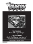
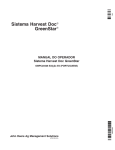
HW H
CORPORATION
R
SERVICE MANUAL
HWH TOUCH PANEL-CONTROLLED
305/325 SERIES LEVELING SYSTEM
R
FEATURING:
Touch Panel Leveling Control
BI-AXIS Hydraulic Leveling
Central Grounding
Straight-Acting Jacks
With or Without Air Dump
R
HWH HYDRAULIC LEVELING
LEVEL
STORE
OFF
CAUTION!
UNDERSTAND OPERATOR’S MANUAL BEFORE USING. BLOCK FRAME AND TIRES
SECURELY BEFORE REMOVING TIRES OR CRAWLING UNDER VEHICLE.
HWH CORPORATION
(On I-80, Exit 267 South)
2096 Moscow Road | Moscow, Iowa 52760
Ph: 800/321-3494 (or) 563/724-3396 | Fax: 563/724-3408
www.hwh.com
ML33832/MI91.0025
10JAN05
SECTION 1
N
TIO
SEC
1
E
UBL
O
R
T
TING
O
O
SH IDE
GU
SEC
TION
2
FIGU
RES
2 PART FOLDER
HOW TO USE MANUAL
This manual is written in two sections. Section 1 is the Trouble Shooting Guide. Section 2 is the figures. Begin diagnosis of
the system with Section 1, the Trouble Shooting Guide. The Trouble Shooting Guide describes system operation with each
phase of operation followed by symptoms of possible problems. The problem section is broken into 3 columns, Problem,
Solutions and Figures. Under Problems, find the symptom you have encountered. The testing and repair for that problem is
in the Solution (center) column. Diagrams for a particular Problem and Solution are in the Figures (right hand) column. This
column will direct you to the proper figure in Section 2, Figures, for a more detailed view.
Before beginning your repair, it is IMPORTANT to read the CAUTIONS and NOTES AND CHECKS in the first section, TROUBLE
SHOOTING GUIDE. In many cases this will save time and mistakes when trouble shooting a system.
This Repair Manual is offered as a guide only. It is impossible to anticipate every problem or combination of problems. For
any problems encountered that are not addressed in this manual, contact HWH Corporation for assistance. (800-321-3494)
PROCEED WITH TROUBLE SHOOTING GUIDE
MI91.115C
27OCT03
TROUBLE SHOOTING
WARNING!
BLOCK FRAME AND TIRES SECURELY BEFORE CRAWLING UNDER VEHICLE. DO NOT USE THE LEVELING
JACKS OR AIR SUSPENSION TO SUPPORT VEHICLE WHILE UNDER VEHICLE OR CHANGING TIRES. VEHICLE
MAY DROP AND OR MOVE FORWARD OR BACKWARD WITHOUT WARNING CAUSING INJURY OR DEATH.
WHEN ROUTING OR REROUTING HYDRAULIC HOSES AND WIRES, BE SURE THEY ARE NOT EXPOSED TO ENGINE
EXHAUST OR ANY HIGH TEMPERATURE COMPONENTS OF THE VEHICLE.
NEVER PLACE HAND OR OTHER PARTS OF THE BODY NEAR HYDRAULIC LEAKS. OIL MAY CUT AND
PENETRATE THE SKIN CAUSING INJURY OR DEATH.
SAFETY CLASSES ARE TO BE WORN TO PROTECT EYES FROM DIRT, METAL CHIPS, OIL LEAKS, ECT. FOLLOW
ALL OTHER SHOP SAFETY PRACTICES.
NOTES AND CHECKS
Read and check before proceeding with Trouble Shooting Steps.
NOTE: HWH CORPORATION ASSUMES NO LIABILITY
FOR DAMAGES OR INJURIES RESULTING FROM THE
INSTALLATION OR REPAIR OF THIS PRODUCT.
1. If the jacks cannot be retracted, see TROUBLE SHOOTING
Step 4h for temporary measures. Make sure the manual
retract valves are closed before trouble shooting.
2. The Trouble Shooting Guide must be followed in order.
Problems checked for in one step are assumed correct and
may not be checked again in following steps.
3. Check that the oil reservoir is full with the jacks in the fully
retracted position. If the vehicle is equipped with HWH room
extensions, refer to the HWH Owners Manual for proper
position of the room when checking the oil level.
4. Most coaches have more than one battery; one for the engine
and the other(s) for the coach. The engine battery supplies
power for the control box and hydraulic pump. Batteries under
no load should read 12.6 volts. Batteries must maintain good
voltage under load. Batteries must be in good condition with
no weak cells. An alternator, converter or battery charger will
not supply enough power for the system to operate properly.
6. Do not replace the control box unless the Repair Steps say
to replace it. Otherwise the malfunctions may damage the
new control box.
This manual is intended for use by experienced mechanics
with knowledge of hydraulic and automotive electrical
systems. People with little or no experience with HWH
leveling systems should contact HWH technical service
(800-321-3494) before beginning. Special attention should
be given to all cautions, wiring, and hydraulic diagrams.
Special note: When installing a new control box, make
sure the box is properly grounded before applying power
to the system.
Tightening of hose ends: If tightening a new hose end,
make the hose end snug (finger tight) on the fitting, then
tighten the hose end 1/3 turn (2 FLATS). If tightening an
existing hose end, tighten the hose end to snug plus 1/4
turn (1 FLAT).
Suggested tools for trouble shooting the HWH leveling systems:
JUMPER WIRES (UP TO 10 GAUGE)
PRESSURE GAUGE (3500 PSI MIN.)
MULTI-METER
12 VOLT TEST LIGHT
5. Proper grounding of all components is critical. See the
electrical circuit for specific grounds required. Faulty grounds,
especially for the control box, solenoid manifold or the pump
assembly, may cause control box component damage and /or
improper or erratic operation.
PROCEED WITH THE TROUBLE
SHOOTING STEPS ON THE
FOLLOWING PAGE
MI91.1169
25APR11
CONTROL IDENTIFICATION
FRONT RETRACT BUTTON
HWH HYDRAULIC LEVELING
FRONT EXTEND BUTTON
LEVEL MODE LIGHT
"LEVEL" BUTTON
LEVEL
WARNING LIGHTS (4-Red)
STORE LIGHT
"STORE" BUTTON
RIGHT SIDE EXTEND BUTTON
STORE
RIGHT SIDE RETRACT BUTTON
LEFT SIDE EXTEND
BUTTON
"OFF" BUTTON
LEVEL LIGHTS (4-Yellow)
OFF
REAR EXTEND BUTTON
CAUTION!
LEFT SIDE RETRACT
BUTTON
REAR RETRACT BUTTON
UNDERSTAND OPERATOR’S MANUAL BEFORE USING. BLOCK FRAME AND TIRES
SECURELY BEFORE REMOVING TIRES OR CRAWLING UNDER VEHICLE.
CONTROL FUNCTIONS
CONTROL BUTTONS
INDICATOR LIGHTS
"LEVEL" BUTTON: This button places the system in
leveling mode.
LEVEL MODE LIGHT: This light indicates the system is in
the leveling mode.
"OFF" BUTTON: This button turns off control power to the
leveling system.
STORE LIGHT: This light will be on when the system is in
the store mode.
"STORE" BUTTON: This button will retract all four jacks.
(The panel must be off before pressing the "STORE" button)
LEVELING LIGHTS: If a yellow LEVELING light is on, that
indicates a side, corner, or end of the vehicle is low. Extend
the appropriate jack pairs to put out the yellow light. One or
two yellow LEVELING lights can be on at a time. The vehicle
is level when all yellow lights are out.
EXTEND BUTTONS (UP ARROWS): These buttons will
extend their respective jack pairs to lift the vehicle.
RETRACT BUTTONS (DOWN ARROWS): These buttons
will retract their respective jack pairs to lower the vehicle.
FRONT - Right Front and Left Front jacks.
RIGHT SIDE - Right Front and Right Rear jacks.
LEFT SIDE - Left Front and Left Rear jacks.
REAR - Left Rear and Right Rear jacks.
WARNING LIGHTS: A red WARNING light will be on whenever the corresponding jack is extended approximately
1/2 inch, provided the ignition is in the "ACC" or "ON"
position. Some vehicles are equipped with a dash mounted
master "JACKS DOWN" light which will be on when one or
more jacks are extended approximately 1/2 inch and the
ignition is in the "ON" position.
WARNING BUZZER: A buzzer will sound if a jack is
extended approximately 1/2 inch or more and the ignition
switch is in the "ON" position.
MI91.1175
28JUL04
TROUBLE SHOOTING
The 325 series leveling system is a manually operated
system. Push and hold the Up Arrow (EXTEND) buttons
and Down Arrow (RETRACT) buttons to operate the jacks.
The jacks will always extend in pairs both front, both rear,
right front and right rear or left front and left rear. When
testing the system, always operate all 4 sets of buttons.
This assures the correct pair of jacks will extend or retract
when their button is pushed.
Vehicles with an active air suspension will have an air dump
system. This will be an HWH system with several normally
closed dump valves or a factory installed pilot air dump
system which is part of the chassis equipment. This manual
will discuss diagnostics of each.
If the vehicle is equipped with a pilot air dump system,
the diagnostics for HWH is limited to a +12 Travel or Dump
signal from the HWH Touch Panel and Control Box. Refer
to the chassis manufacturer for the correct procedures when
working on the chassis pilot dump equipment.
In the following repair guide, each "Part" describes an
operation or function of the leveling system. Below each
"Part" there are three columns. The left hand column
describes a possible symptom. The center column gives a
diagnostic procedure and solution. The right hand column
shows a diagram or refers to a diagram in the diagram section.
It is important to remember it is possible to encounter a
problem not listed in this guide. If this occurs, contact HWH
Corporation Customer Service for assistance.
Part 1. Make sure the transmission is in the recommended position for parking and the park brake is set. With the ignition off,
there should be no power to the leveling system. There should be no Touch Panel lights on. The pump should not be running.
PROBLEM
SOLUTION
1a. The Touch Panel
has a light on or can
be turned on with
the ignition off.
Wire number 6122 on PIN 1 of CN1 on the touch panel
should be connected to a +12 source on the accessory side
of the ignition switch. There should be no power on this wire
with the ignition off.
1b. The pump runs
continuously.
Unplug CN2 from the control box. If the pump continues to
run, the pump relay is stuck and needs to be replaced. If the
pump stops running, unplug CN1 from the control box and
plug CN2 back in. If the pump starts running the control box
is bad. If the pump does not run unplug CN3 from the touch
panel and plug CN1 back in. If the pump runs wire 8600 in
the harness is shorted to ground. If the pump does not run,
the touch panel is the problem.
DIAGRAM
CN1
3AMP
FUSE
ACC.
REFER TO MP85.192C
BROWN - CN2
GRAY CN-1
REFER TO MP85.206C
3AMP
FUSE
ACC.
CN3
REFER TO MP85.192C
Part 2. Turn the ignition switch to the "ACC" position. The touch panel should remain off.
PROBLEM
SOLUTION
2a. The Level Mode
light and/or other
are on.
Push the "OFF" button. If panel lights stay on,
replace the touch panel.
2b. The pump runs
at this time.
Unplug CN2 from the control box if the pump continues to
run, replace the control box. If the pump stops, replace the
Touch Panel.
DIAGRAM
BROWN - CN2
REFER TO MP85.206C
Part 3. With the ignition in the "ACC" position, push the "LEVEL" (I) button. The red LEVEL MODE light should glow steady.
One or two yellow LEVEL lights may be on. No other lights should be on. The pump should not run. If the vehicle is equipped
with an air suspension, the air will dump from the suspension when the Touch Panel is turned on. If the Touch Panel comes
on but will not dump at this time, see part 6.
PROBLEM
SOLUTION
3a. The Level Mode
light will not come
on when the LEVEL
button is pushed.
Check PIN 1 wire number 6120 of connector CN1 of the Touch
Panel. There should be a good +12 volt signal with the ignition
in the "ACC" position. Check PIN 3 wire number 6230 of
connector CN3 of the Touch Panel. This should be a good
ground. If +12 volts and ground is present, replace the Touch
Panel.
DIAGRAM
CN1
3AMP
FUSE
ACC.
CN3
REFER TO MP85.192C
MI91.2068
31JUL07
TROUBLE SHOOTING
PROBLEM
SOLUTION
3b. The LEVEL
MODE light will
come on but will
not stay on when
the LEVEL button
is released.
Use a volt meter to check between PIN 1 of connector CN1
and PIN 3 of connector CN3 of the Touch Panel while pushing
the LEVEL button. If there is less than 11 volts, there is a wire,
connection or battery problem. If there is 12 + volts while
pushing the LEVEL button, replace the Touch Panel.
3c. More than two
or opposite yellow
level lights are on.
With the panel on, unplug the Sensing Unit connector, CN4.
Use a test light to ground pins 2 (rear), 3 (right side), 4 (front)
and 5 (left side). If the correct light does not come on at once
replace the Touch Panel. If the Touch Panel works properly,
plug in CN4 at the Touch Panel and unplug CN3 at the Control
Box. Use a test light to ground PIN 1 (rear), 2 (right side),
3 (front) and 4 (left) of the harness plug. If the correct light
does not come on or two lights come on, the harness is the
problem. If the panel lights work properly, replace the Sensing
Unit.
3d. A red warning
light is on, no jacks
are extended.
DIAGRAM
CN1
3AMP
FUSE
ACC.
CN3
REFER TO MP85.192C
Unplug the CN2 connector at the Touch Panel. If the warning
light remains on, replace the Touch Panel. If the warning
light(s) goes out, plug the CN2 connector back in and unplug
the warning switch at the jack. If the warning light remains on,
the harness is bad. If the light goes out the problem is probably
the warning switch. If a new switch does not fix the problem
the magnet in the cylinder may be bad.
CN4
3AMP
FUSE
ACC.
CN3
REFER TO MP85.192C
GRAY - CN3
REFER TO MP85.206C
CN2
3AMP
FUSE
ACC.
CN3
REFER TO MP85.192C
NOTE: Make sure the white wires of the harness and
warning switch are in the "A" pins of the Packard
connectors. The black wires must be in the "B" pins
of the connectors.
3e. The pump runs
when the touch
panel is turned on.
Replace the touch panel.
3f. The air will not
dump from the
suspension when
the Touch Panel
is turned on.
See Part 6 of the TROUBLE SHOOTING STEPS.
MI91.2078
15MAY08
TROUBLE SHOOTING
The jacks operate in pairs, front, side and rear. UP ARROWS - EXTEND and DOWN ARROWS - RETRACT the jacks.
Part 4. Push and hold the front UP ARROW, both front jacks should extend. At approx. 1/4" to 1/2" extension each red Warning
light should come on. One jack may reach the ground and even lift the vehicle slightly before the other. With both jacks
extended to the ground and lifting the vehicle release the UP ARROW, both jacks should remain extended. Push and hold the front
DOWN ARROW, both front jacks should retract. Within 1/4" to 1/2" of complete retraction each red Warning light should go out.
Repeat the process with each set of UP and DOWN ARROWS making sure the correct
pair of jacks extend and retract properly. Three or four jacks should never extend at the same time.
PROBLEM
SOLUTION
4a. The Panel is on,
the pump does not
run when the UP
ARROW is pushed.
(Try a different UP
ARROW. If the
pump runs replace
the Touch Panel.)
While the UP ARROW is pushed, there should be +12 volts on
terminals 1,2 and 3 of the pump relay. Terminal 4 is a ground
supplied by the park brake switch. Terminal 1 is battery power to
the relay. Terminal 2 is switched +12 power to the pump motor.
(Make sure all pump assembly mounts are tight and that the
assembly has a adequate ground for the pump motor.) Terminal 3
is switched +12 volts to control the relay. Terminals 1,2 and 3
should have a minimum of 9.0 volts when trying to run the pump.
DIAGRAM
PUMP RELAY
8600
1
6100
2
3
4
FROM
COACH
BATTERY
TO
PUMP
MOTOR
9000
PUMP
9
10
F5
If there is no power on terminal 1 check connection to the
battery, the battery and the ground connections for the battery.
REFER TO MP85.2195
F2
Check LED 9 (yellow) and LED 10 (red) for the pump relay in the
Control Box. If both LED’s are lit: Check terminal 3 of the pump
relay. If power is present skip to the next paragraph. If power is
not present the problem is with the connections (CN2-PIN 12) or
the wire (8600). If the yellow LED is lit but but not the red:
Check the fuse. If the fuse is OK, check the 6100 wires in the
4 PIN gray connector for +12 volts. If voltage is present, replace
the Control Box. If voltage is not present, the problem is the 6100
wire, connections at the pump relay or no power from the battery.
Check that the CN2 brown connector is plugged in properly. This
connector can be plugged in upside down. If the fuse is bad,
the problem is the 8600 wire or the pump relay. If the yellow
LED is not lit: Check CN1 PIN 12 of the control box for 12 volts
and PIN 11 for ground. If PIN 12 has +12 volts and PIN 11 has a
ground replace the Control Box. If PIN 12 has no voltage check
CN3 PIN 1 at the Touch Panel. If voltage is present the problem
is the connection or wire (6120) of that harness. If voltage is not
present, replace the Touch Panel. If PIN 11 (CN1) of the control
box has no ground, check CN3 PIN 10 at the Touch Panel. If PIN 10
has a ground the problem is the connections or wire (8600).
If PIN 10 has no ground, replace the Touch Panel.
LED
REFER TO MP85.212C
BROWN - CN2
PIN 12
PIN 1
PIN 1
GRAY CN-1
GRAY
PIN 12
If there is power on terminals 1,2 and 3 the problem is
connections to the pump motor or the pump motor itself.
If there is power on terminals 1 and 3, ground on terminal 4,
but no power on terminal 2 the pump relay is bad.
REFER TO MP85.206C
AND
REFER TO MP85.207C
If there is no ground on terminal 4, check CN2 PIN 7. If ground
is present, the connections or wire (9000) is the problem. If there
is no ground on PIN 7, check CN1 PIN 7 for ground. If there is a
ground, replace the Control Box. If there is no ground in PIN 7 (CN1)
the problem is the connections, wire (9000) or the park brake circuit.
3AMP
FUSE
ACC.
CN3
Note: Make sure all connections at the relay are clean and tight.
Corrosion that may not be visible can cause problems at the relay.
Remember, the UP ARROW must be pushed when testing the
relay.
REFER TO MP85.192C
MI91.2098
29JUN04
TROUBLE SHOOTING
PROBLEM
4b. The jack(s) will
not extend or will
extend but will not
lift the vehicle. The
pump runs under
no load.
SOLUTION
If the pump is running under no load the problem is the pump
or the shuttle valve. Connect a 5000 PSI pressure gauge to
the pressure outlet fitting on the manifold. Run the pump. The
pump pressure should be 3500 PSI. Check the voltage at the
pump while the pump is running. If the voltage is under
10 volts the pump pressure may be low. The minimal allowable
pressure would be 3300 PSI. The maximum allowable pressure
would be 3800 PSI. The pumps have an adjustable relief valve.
If proper pressure cannot be achieved, replace the pump.
DIAGRAM
PRESSURE
OUTLET
CHECK
VALVES (4)
LR
LF
SHUTTLE
VALVE
RR
RF
NOTE: SOME
MANIFOLDS
ARE EQUIPPED
WITH VELOCITY
VALVES
50 PSI
PRESSURE
SWITCH
REFER TO MP65.270C
6
F5
F4
8
FUSE
F6
LED
F7
F12
If after replacing the control box the jacks will still not extend,
refer to part 4d and check individual pairs of jacks.
RIGHT
REAR
OUTPUT
F3
4
If the YELLOW and RED LED’s come on while pushing the
"DOWN" arrows, the touch panel and touch cable are OK.
PIN1
CN4
REFER TO MP85.212C
P.E.D
P.E.D
P.E.D
8100
RR
RF
50 PSI
PRESSURE
SWITCH
LF
LEVELING
MANIFOLD
P.E.D
If the LED’s come on refer to problem 4b and check the pump
pressure and voltage. If the pump pressure and voltage is OK,
open any valve release T-Handle or nut. Push the appropriate
"UP" arrow for that jack. If the jack does not extend, the
problem is the shuttle valve. If the jack extends, unplug the 50
PSI manifold pressure switch and close the valve releases on
the solenoid valves. Ground the 8100 wire and try any "UP"
arrow. If the jacks extend, replace the pressure switch. If the
jacks do not extend the problem is the 8100 wire, it’s
connections or the control box. Check for continuity between
the two pins for the 8100 wire. If the wire and connections are
OK replace the control box.
7
5
3
F2
2
LEFT
FRONT
OUTPUT
1
F1
Left Front - LED’s 5 and 6
Right Front - LED’s 3 and 4
Right Rear - LED’s 7 and 8
Left Rear - LED’s 1 and 2
RIGHT
FRONT
OUTPUT
The problem is most likely the 50 psi manifold pressure switch
but could be the shuttle valve, control box, touch panel or
touch panel cable.
LEFT
REAR
OUTPUT
4c. No jacks will
extend, the pump
runs under load.
LR
REFER TO MP85.2195
MI91.2108
28JUL04
TROUBLE SHOOTING
RIGHT
REAR
OUTPUT
6
F5
F4
4
7
5
3
2
F3
8
FUSE
F6
LED
F7
F12
If the YELLOW and RED LED’s are both lit or the YELLOW
LED’s are lit but not the RED LED’s the problem is between
the control box and the hydraulic manifold.
1
LEFT
FRONT
OUTPUT
NOTE: Remember
when refering to 4d
from 4c, the
manifold pressure
switch and shuttle
valve have been
checked and are OK.
Left Rear - LEDs 1 and 2
Right Front - LEDs 3 and 4
Left Front - LEDs 5 and 6
Right Rear - LEDs 7 and 8
F2
Check the YELLOW and RED LED’s for the jack(s) that won’t
extend while the UP ARROW is being pushed.
RIGHT
FRONT
OUTPUT
4d. One or more
jacks or the correct
jacks will not
extend when an
"UP" arrow is
pushed. Other
jacks extend OK.
DIAGRAM
F1
SOLUTION
LEFT
REAR
OUTPUT
PROBLEM
PIN1
CN4
REFER TO MP85.212C
If the YELLOW and RED LED’s are not lit, the problem is
between the control box and the touch panel.
BROWN - CN2
Note: Remember when checking for voltage or ground
all harnesses must be plugged in and the correct
UP ARROW must be pushed.
The signal between the touch panel and the control box to
run the pump and solenoid valves is a ground signal. The
signal between the control box and the pump relay or
jack solenoid valves is a +12 volt signal.
PIN 12
PIN 1
PIN 1
GRAY CN-1
GRAY
PIN 12
REFER TO MP85.206C
If the YELLOW and RED LED’s are lit check the correct pins
in the BROWN CN2 connector for +12 and ground. If +12
or ground is not present replace the control box. If +12 and
ground is present check for +12 and ground at the solenoid
valve. If +12 or ground is not present the harness is the
problem. If +12 and ground is present at the solenoid valve,
replace the solenoid valve.
If the YELLOW LED is lit but not the RED LED, check the
fuse for that valve. If the fuse is OK, replace the box. If the
fuse is blown, the problem is a short in the harness or a bad
solenoid valve.
3AMP
FUSE
ACC.
CN3
REFER TO MP85.192C
If neither the YELLOW LED or the RED LED is lit, check for
a ground on the correct pin in the CN1 GRAY 12 pin connector
at the control box. If a ground is present, replace the control
box. If a ground is not present, check for a ground on the
correct pin in the CN3 - 11 pin connector at the touch panel.
If a ground is present, the problem is the harness or harness
connections. If a ground is not present, replace the touch panel.
MI91.2118
29JUN04
TROUBLE SHOOTING
B A
2000
LF
P.E.D
RF
6235
TOUCH PANEL/
CONTROL BOX
CONNECTION
CABLE
RF
WARNING
SWITCH
HARNESS
SEE ELECTRICAL
CONNECTION
DIAGRAMS
CONTROL BOX/
PUMP/MANIFOLD
CONNECTION
INFORMATION
6235
3000
B A
LR
RR
4000
LR
P.E.D
The ignition must
be on while testing
warning switches.
6235
1000
LF
B A
Unplug the warning switch at the jack. Short the two pins in
the harness plug together. If the warning light comes on,
replace the warning switch. (Retract the jacks before removing
the warning switch.) If the warning light does not come on,
ground the pin for the black wire in the harness. If the warning
light comes on, the problem is the white ground wire or it’s
connections. If the light does not come on, ground the correct
pin in the CN2 connector at the touch panel. If the warning
light comes on, there is a connection or harness problem. If
the warning light does not come on, replace the touch panel.
B A
4e. The red
WARNING light on
the Touch Panel
will not come on
as it’s jack starts
to extend.
DIAGRAM
D.E.P
SOLUTION
D.E.P
PROBLEM
6235
RR
REFER TO MP85.047C
CN2
3AMP
FUSE
ACC.
REFER TO MP85.192C
The ignition must
be on.
5-15 AMP FUSE
CONNECT THIS END TO
+12 VOLT IGNITION "ON" POWER
PIGTAIL W/DIODE
AND IN-LINE
FUSE HOLDER - 6121
JACK
DOWN
LIGHT
BUZZER
+
Check for +12 power at the warning light and buzzer. If +12
is not present, trace the wire to it’s source. If the fuse is blown,
the +12 supply wire is shorted to ground. If +12 is present at
the warning light and buzzer, check for a ground on PIN 4,
CN1 of the touch panel. If ground is not present replace the
touch panel. If ground is present, check for a ground at the
warning light and buzzer. If a ground is present, the problem
is the light or buzzer. If a ground is not present, the problem is
a connection or the 7699 wire.
IGNITION
4f. The Master
Warning light and/or
buzzer will not
come on when a
Touch Panel
warning light is on.
7699
6111
WARN LIGHT
CONTROL
6111
_
7699
BUZZER
CONTROL
PIGTAIL PROVIDED - 7699
REFER TO MP85.304Q
CN1
3AMP
FUSE
ACC.
REFER TO MP85.192C
MI91.2128
29JUN04
TROUBLE SHOOTING
PROBLEM
CAUTION: THE VEHICLE MUST BE PROPERLY
RIGHT
REAR
OUTPUT
LEFT
FRONT
OUTPUT
7
5
F3
F2
F4
3
6
4
F5
1
2
8
FUSE
F6
LED
F7
F12
Check the YELLOW and RED LED’s for the jacks that will not
retract. If both LED’s are lit, Manually open the solenoid valve
for the jack that will not retract. If the jack does not retract,
loosen the hose for the jack(s) that will not retract. This can be
done at the jack or hydraulic manifold.
RIGHT
FRONT
OUTPUT
SUPPORTED SO THE VEHICLE CAN NOT DROP IF
PERFORMING A TEST WOULD PLACE A TECHNICIAN
UNDER THE VEHICLE.
F1
NOTE: Remember
when checking for
voltage or grounds,
all harnesses must
be plugged in and
a DOWN ARROW
must be pushed.
DIAGRAM
LEFT
REAR
OUTPUT
4g. One or more
jacks will not
retract while the
DOWN ARROW
is being pushed.
SOLUTION
PIN1
CN4
IMPORTANT: This may cause the vehicle to drop and
cause a loss of fluid.
If the jack does not retract replace the jack. If the jack retracts
the problem may be the check valve or the velocity valve if so
equipped. With the solenoid valves closed and the system off,
remove the outer check valve. Replace the cap and retry. If
the jack retracts, replace the check valve. If the jack does not
retract, replace the velocity valve.
If the jack retracts when the solenoid valve is manually opened,
check for voltage at the solenoid valve for the jack(s) that will
not retract. If voltage is present, replace the solenoid valve.
If voltage is not present, there is a connection problem between
the control box and manifold.
Check the yellow and red LED’s for the solenoid valve while
pushing DOWN ARROWS. (It is assumed jacks will extend
when UP ARROWS are pushed.
If the YELLOW LED is lit but not the RED LED, check the
fuse for that valve. If the fuse is blown, the solenoid valve or
harness is shorted to ground. If the fuse is not blown, replace
the control box. If neither LED is lit, replace the touch panel.
REFER TO MP85.212C
BREATHER
CAP
VALVE
RELEASE
"T" HANDLES
VALVE
RELEASE
NUTS
PRESSURE
OUTLET
CHECK
VALVES (4)
LR
LF
RF
RR
NOTE: SOME
MANIFOLDS
ARE EQUIPPED
WITH VELOCITY
VALVES
SHUTTLE
VALVE
50 PSI
PRESSURE
SWITCH
PUMP/MANIFOLD
ASSEMBLY
REFER TO MP65.270C
MI91.2138
18MAY05
TROUBLE SHOOTING
PROBLEM
4h. No jacks will
retract when DOWN
arrows are pushed.
(It is assumed jacks
will extend when
UP ARROWS are
pushed)
SOLUTION
DIAGRAM
Check the YELLOW and RED LED’s for the solenoid valves
while pushing DOWN arrows. If the LED’s are coming on,
manually open the solenoid valves. If the jacks do not retract
the problem is most likely the shuttle valve. Loosen a hydraulic
hose for a jack. The jack should start to retract. If the jack
does not retract the problem is the jack. If the jack starts to
retract replace the shuttle valve. If the YELLOW and RED
LED’s are not coming on, while pushing the DOWN arrows,
check for a ground on PIN 11 of CN3 at the touch panel and
PIN 5 of the 12 pin GRAY connector (CN-1) at the control box
while pushing DOWN arrows. If a ground is not present at the
touch panel on PIN 11, replace the touch panel. If there is a
ground at the touch panel but not at the box on PIN 5, there is
a connection or harness problem. If there is a ground at the
control box on PIN 5 replace the control box.
FOR JACK RETRACTION
SOLENOID VALVES
REFER TO MP65.270C
3AMP
FUSE
ACC.
CN3
REFER TO MP85.192C
PIN 1
GRAY CN-1
GRAY
PIN 12
REFER TO MP85.206C
4j. A red Warning
light on the Touch
Panel will not go out.
The jacks are fully
retracted.
Unplug the warning switch at the jack. If the warning light goes
out, replace the warning switch. If replacing the switch does
not fix the problem, the cylinder may need to be replaced.
Contact HWH Technical Service for assistance.
6235
B A
B A
D.E.P
RF
6235
TOUCH PANEL/
CONTROL BOX
CONNECTION
CABLE
RF
WARNING
SWITCH
HARNESS
SEE ELECTRICAL
CONNECTION
DIAGRAMS
CONTROL BOX/
PUMP/MANIFOLD
CONNECTION
INFORMATION
3000
B A
B A
6235
D.E.P
NOTE: Make sure the white wires of the harness and
warning switch are in the "A" pins of the Packard
connectors. The black wires must be in the "B" pins
of the connectors.
2000
LF
1000
LF
P.E.D
If a jack will not retract completely, the problem is most likely
the jack.
If a jack retracts slowly, more than three minutes above
55 degrees outside temperature or more than five minutes at
freezing, loosen the hose for that jack. If that does not increase
the retract speed, replace the jack. If the jack retracts at a
normal speed with the hose loose, the problem would be the
velocity valve or solenoid valve.
LR
LR
P.E.D
4i. One or more
jacks retract slowly
or start to retract
but will not retract
completely.
RR
4000
6235
RR
REFER TO MP85.047C
If the warning light does not go out with the warning switch
unplugged, remove the wire for that switch from CN5 at the
touch panel. If the light goes out the wire is shorted to ground.
If the light does not go out, replace the touch panel.
CN2
3AMP
FUSE
ACC.
REFER TO MP85.192C
4k. The Master
Warning light
and/or buzzer will
not go out. All
Warning lights on
the Touch Panel
are off.
Disconnect the 7699 wire from the CN1 connector at the
touch panel. If the master warning light and buzzer turn off,
replace the touch panel. If they remain on, the 7699 wire is
shorted to ground.
CN1
3AMP
FUSE
ACC.
REFER TO MP85.192C
MI91.2148
15MAY08
TROUBLE SHOOTING
Part 5. "STORE" button. The "STORE" button is used to retract all of the jacks at the same time. The "STORE" button will
also put the suspension in the TRAVEL MODE if the vehicle is equipped with a pilot air dump system. The LEVEL MODE light
must be OFF to use the "STORE" button. The "STORE" button will not work if the LEVEL MODE light is ON. The ignition
must be in the "ON" or "ACC" position for the "STORE" button to function. Push the "STORE" button. The STORE light
will come on steady. All four jacks will start to retract. If the vehicle is equipped with an air suspension, the suspension should
start to return to ride height at this time. As each jack is completely retracted (within 1/4 to 1/2 inch) it’s red warning light on the
touch panel will go out and it’s solenoid valve will turn off. When all of the red warning lights are out, the master warning light
and buzzer will be off. The STORE light will remain on until the "OFF" button is pushed or the ignition key is turned.
NOTE: The park brake does not have to be on to use the "STORE" button. The "STORE" light should be
on whenever the vehicle is traveling.
PROBLEM
5a. The STORE light
will not come on
when the "STORE"
button is pushed.
light is on.
SOLUTION
DIAGRAM
Push the LEVEL MODE button. If the LEVEL MODE light
comes on, push the "OFF" button. Make sure the LEVEL MODE
light is OFF. Retry the "STORE" button. If the STORE light
does not come ON replace the touch panel.
If the LEVEL MODE light does not come ON when pushing the
LEVEL MODE button, refer to problem 3a.
5b. The STORE light Check voltage between PIN 1 (CN1) and PIN 3 (CN3) at the
will not stay on.
touch panel. If there is 11+ volts while pushing the "STORE"
button and the STORE light does not come ON, replace the
touch panel. If the voltage is bellow 11 volts, there may be a
ground, wire, connection or voltage problem.
CN1
3AMP
FUSE
ACC.
CN3
PIN 1
REFER TO MP85.192C
5c. The STORE light If a red jack down warning light is not on, it’s jack will not
is on, the jacks will retract. Refer to part 4e to diagnose warning light issues.
not retract.
It is assumed at this point the jacks will retract properly
using the DOWN arrows on the touch panel. If some jacks will
retract, but one or more jacks will not retract, recheck problems
4g and 4h. If the jacks retract properly, replace the touch panel.
PIN 1
GRAY CN-1
PIN 12
5d. The STORE light Recheck problems 4j and 4k to make sure the jacks retract
is on, NO jacks will properly in the manual mode. With the "STORE" light on check
retract.
pins 4,6,7,8 and 9 of CN3 at the touch panel for ground.
If ground is not present on pins 4,6,7,8 or 9, replace the touch
panel. If ground is present on these pins, check pin 3, CN1 at
the control box for ground. If ground is not present, the problem
is the cable or the connections to the touch panel or control box.
If ground is present, replace the control box.
5e. The vehicle will
not return to ride
height.
Proceed to Part 6.
5f. The Warning
lights on the Touch
Panel or the
Master Warning
light and buzzer
will not turn off.
Again it is assumed these items have been checked and are
functioning properly. If there is a problem with the touch panel
warning lights or master warning light and buzzer at this time,
refer to problems 4j and 4k.
REFER TO MP85.206C
MI91.2158
24AUG10
TROUBLE SHOOTING
Part 6. This part is for vehicles with an air suspension.
The air must be dumped from the vehicle air suspension before leveling the vehicle. This is done with a HWH air dump system
or a pilot air dump system supplied by the chassis manufacturer.
The HWH air dump system consists of a minimum of one normally closed, +12 volt actuated solenoid valve at the front and
one valve at the rear of the vehicle. Some vehicles have one air dump valve for each height control valve. There are 2 wires
to each valve. The white wire is constant ground. The black 9300 wire is switched +12 volts to open the valve. The 9300 wire
will be hot whenever the LEVEL MODE LIGHT is on. The valve should open and the air should exhaust from the vehicle
suspension and air tanks. When the LEVEL MODE light is off, the air dump valves should be closed. Air should not leak
through the valves.
The chassis supplied pilot dump system has two positions. One position is the "TRAVEL" mode which allows the height
control valves to work. The other position is the "DUMP" mode which will exhaust the air from the suspension air bags only.
There are three wires in a four pin UML plug from HWH to operate the pilot valve. The 9300 wire is switched +12 when the
LEVEL MODE light is on to put the system in the "DUMP" mode. The 9301 wire is switched +12 when the "STORE" light is on
to put the system in the "TRAVEL" mode. The white wire is constant ground. The ignition must be on to have power on the
9301 wire. The 9301 wire will be hot any time the ignition is on if the park brake is off. HWH is only responsible for the three
wires from the control box to the four pin UML plug. All other harnesses and equipment are supplied by the chassis or vehicle
manufacturer.
PROBLEM
SOLUTION
6a. Air will not
dump from the
suspension when
the LEVEL MODE
light is on.
WHEN TESTING THE AIR DUMP SYSTEM
MAKE SURE THE VEHICLE IS SUPPORTED PROPERLY
BEFORE GOING UNDER THE VEHICLE. THE VEHICLE
WILL DROP SUDDENLY WHEN THE AIR IS EXHAUSTED
FROM THE AIR BAGS.
NOTE: The HWH
and the pilot dump
system will be the
same basic tests
for dumping air.
Check the YELLOW (11) LED and the RED (12) LED in the
control box. If neither LED is lit, check for a ground on PIN 5,
CN3 connector at the touch panel and PIN 6, 12 pin GRAY
(CN1) connector at the control box. If there is no ground at the
panel, replace the touch panel. If there is a ground at the panel
but not the control box, the problem is a connection or the 9300
wire in the harness. If there is a ground on PIN 6 at the control
box, replace the control box.
DIAGRAM
CAUTION:
F5
F3
F4
F2
F1
FUSE
12
F6
F7
LED
11
DUMP
F12
REFER TO MP85.212C
BLACK - CN5
PIN 12
REFER TO MP85.207C
AIR DUMP
VALVE
9300
6230
DUMP
9300
6230
AIR DUMP
VALVE
9300
B A
P.E.D
DUMP
Note: There is one 9300 wire from the control box to control
the dump valves, either HWH valves or the chassis pilot dump
valve.
P.E.D
B A
B A
DUMP
P.E.D
If the YELLOW (11) LED is lit but not the RED (12) LED,
check the fuse. If the fuse is blown there is a short to ground
in the 9300 wire that is in the 12 pin BLACK connector (CN5)
at the control box or the HWH air valve or pilot valve is shorted.
PIN 1
FOR AIR DUMP
6230
If the fuse is not blown, replace the control box.
REFER TO MP85.2195
(HWH AIR DUMP VALVES)
If the YELLOW (11) LED and the RED (12) LED are both lit,
check for +12 on the 9300 wire and ground on the white wire
at the HWH air dump valves or at the four pin UML plug if the
vehicle is equipped with a pilot dump system. If power and
ground is present, there is a problem with the dump valves or
the pilot dump system if so equipped. Contact the vehicle
manufacturer for assistance with a pilot dump system.
9310-DUMP
Note: If the vehicle is equipped with HWH dump valves, make
sure the exhaust port for the valve is not plugged.
If power is not present at the valve or four pin UML plug, the
problem is with the 9300 wire, the ground wire or their
connections.
9311-TRAVEL
6231-GRND
REFER TO MP85.2215
(PILOT DUMP SYSTEM)
MI91.2168
28JUL04
TROUBLE SHOOTING
DUMP
DUMP
B A
9300
P.E.D
6230
AIR DUMP
VALVE
9300
P.E.D
6b. The vehicle will
not return to ride
height.
AIR DUMP
VALVE
9300
6230
B A
Make sure there is at least 100 psi of air in the vehicle air tanks.
The ignition must be on. Make sure the touch panel LEVEL
MODE light is OFF. If air is not exhausting from the dump valves,
the problem is in the vehicle suspension, most likely a height
control valve. If air is exhausting from the dump valve(s) unplug
the dump valve(s). If the air continues to exhaust from the
valve(s), replace the valve(s).
If the air stops exhausting from the dump valve(s) when they are
unplugged, check for a ground on PIN 5 of CN3 at the touch
panel with the CN3 connector unplugged. If a ground is present,
replace the touch panel. If a ground is not present, unplug the
GRAY 12 pin connector (CN1) at the control box. Check PIN 6
in the harness plug for a ground. If a ground is present, the 9300
wire in the touch panel harness is shorted to ground. If there is
no ground on PIN 6, replace the control box.
B A
For vehicles that
are equipped with
HWH air dump
system.
DIAGRAM
DUMP
SOLUTION
P.E.D
PROBLEM
6230
REFER TO MP85.2195
3AMP
FUSE
ACC.
CN3
REFER TO MP85.192C
GRAY CN-1
REFER TO MP85.207C
F5
F3
F4
F2
FUSE
F6
LED
F7
TRAVEL
F12
6c. The vehicle
will not return to
ride height.
Make sure there is at least 100 psi of air in the vehicle air tanks.
The ignition must be on. Make sure the STORE light is ON.
Check the YELLOW (13) LED and the RED (14) LED for travel.
Both LED’s should be lit. If both LED’s are lit, check for +12
volts between the white ground wire and the 9301 wire in the
HWH 4 pin UML plug. If power is not present, the problem is
either the white ground wire, the 9301 wire or their connections.
If power is present, the problem is with the chassis equipment
or harness. Contact the vehicle manufacturer for assistance.
If the YELLOW (13) LED is lit but not the RED (14) LED,
check the F7 fuse for TRAVEL. If the fuse is OK, replace the
control box. If the fuse is blown, the 9301 wire is shorted to
ground or there is a short in the vehicle pilot dump equipment.
Unplug the HWH 4 pin UML plug. Replace the fuse and retry.
If the fuse blows again the 9301 wire is the problem. If the fuse
does not blow, the vehicle equipment is the problem.
If neither LED is lit, check for a ground on PIN 4, CN3 at the
touch panel. If there is no ground, replace the touch panel.
If there is a ground on PIN 4, check for a ground on PIN 3 in
the 12 pin GRAY connector (CN1) at the control box. If there
is no ground, the problem is the 9301 wire or it’s connections
at the touch panel or control box. If there is a ground on PIN 3,
replace the control box.
F1
For vehicles
equipped with a
pilot air dump
system.
REFER TO MP85.212C
9310-DUMP
9311-TRAVEL
6231-GRND
REFER TO MP85.2215
3AMP
FUSE
ACC.
CN3
REFER TO MP85.192C
PIN 1
GRAY CN-1
PIN 12
REFER TO MP85.207C
MI91.2178
28JUL04
TROUBLE SHOOTING
Part 7. Sensing Unit Test. The sensing unit is located in the control box. There are four yellow LED’s on the sensing unit.
These LED’s will match the yellow Level Sensing lights on the touch panel. With the vehicle level all of the lights on the
sensing unit and the touch panel should be out. If one or two lights are on, adjust the sensing unit according to the SENSING
UNIT ADJUSTMENT page in the diagram section. It is important to note that very small movements of the adjusting nut or
screw should be all that is needed to change the yellow LED’s on the sensing unit. Use the jacks to raise one side or end of
the vehicle at a time to make sure each yellow Level light will come on and go back out.
The sensing unit LED’s can be checked with just the ignition on. The Level Sensing lights on the touch panel can only be
checked if the LEVEL MODE light is on.
PROBLEM
SOLUTION
7a. The Sensing
Unit cannot be
adjusted to turn
off the yellow
LED’s.
Check the sensing unit adjustment bracket for cracks, breaks
or deformities. Make sure the adjustment screw is not stripped
out. If the components of the adjustment bracket are OK,
replace the sensing unit.
7b. The lights on
the touch panel do
not match the lights
on the sensing
unit.
Due to the fact that the control box/ power unit assembly may
be mounted in any one of four directions, the sensing unit may
be programmed to match the mounting direction. Aftermarket
and replacement control boxes and sensing units are equipped
with programming jumpers. If the unit is equipped with these
jumpers, check the programming instructions in the diagram
section to make sure the jumpers are in the correct position.
If the jumpers are correct or the sensing unit is not equipped
with the jumpers, check CN3 and CN4 of the control box and
CN4 of the touch panel to make sure that the wires are in the
proper positions.
If the sensing unit is not equipped with the programming
jumpers, get the AP part number off the control box and contact
HWH to make sure the proper control box is being used.
DIAGRAM
REFER TO
MP85.6148
(Sensing Unit Adjustment)
MP85.451C
MP85.451D
(Jumper Placement)
4
3
2
1
REFER TO MP85.451C
If the wiring, the jumper placement, and the control box is OK,
replace the sensing unit.
7c. Level Sensing
lights cannot be
made to come on
or go out.
Refer to problem 3c.
GRAY - CN3
REFER TO MP85.206C
CN4
3AMP
FUSE
ACC.
REFER TO MP85.192C
MI91.2188
31JUL07
SENSING UNIT MAINTENANCE/SERVICE
SENSING UNIT ACCURACY TOLERANCE
The sensing unit has an accuracy tolerance of ± 5.4 inches front to rear and
± 1 inch side to side on a 36 foot vehicle. Typical leveling results will be better.
SENSING UNIT ADJUSTMENT
To adjust the sensing unit, first the vehicle must be level. Either
position the vehicle on a level surface or use the leveling system
to manually level the vehicle. It is recommended to use the
vehicle trim line to determine level. An alternative would be to
use a small bubble level. If using a bubble level, the level should
be placed on a flat surface close to the mounting location of
the control box/sensing unit.
With the vehicle level , if there are no yellow light lit on the
Touch Panel, the sensing unit is properly adjusted. If there
are yellow LEVEL lights lit on the Touch Panel, manual
adjustments to the Sensing Unit are needed. A Phillips
screw driver or sockets w/driver or box end wrenches of
7/8, 3/4, 1/2, 5/16 or 1/4 sizes will be needed.
The Sensing Unit is mounted inside the Control Box. The
Control Box is mounted to the power unit/valve assembly.
There are four LED’s on the Sensing Unit, A,B,C and D. Refer
to the drawing below. The Sensing Unit is adjusted by turning
the adjustment nut to turn out LED’s B and D. The adjustment
screw will turn out LED’s A and C. If the adjustment nut has
to be turned more than 1/2 flat or the adjustment screw has to
be turned more than 3/4 turn to turn the LED out, there may
be a problem with the Sensing Unit or the mounting of the
Control Box. If two LED’s are on, it is best to make the B-D
adjustments first, then hold the adjustment nut from moving
while making the A-C adjustment.
TOP VIEW - SENSING UNIT
A
LED’S - LOCATION
MAY BE DIFFERENT
D
NOTE: If opposing LED’s are lit, there is a problem with
the Sensing Unit.
If LED (A) is lit: Turn the adjustment screw COUNTER
CLOCKWISE until the LED is off.
If LED (C) is lit: Turn the adjustment screw CLOCKWISE
until the LED is off.
If LED (B) is lit: Turn the adjustment nut COUNTER
CLOCKWISE until the LED is off.
If LED (D) is lit: Turn the adjustment nut CLOCKWISE
until the LED is off.
IMPORTANT: When all 4 LED’s are off, move the
vehicle to an unlevel position so one or two yellow
lights are on. Level the vehicle according to the yellow
LEVEL lights. Recheck the level. If more adjustment is
needed, DO NOT try to adjust the sensing unit until the
yellow level lights go out, instead just "tweak" the
sensing unit, ignoring the LED’s on the sensing unit.
Example: After the initial adjustment and releveling
the vehicle, the front is still low. This means the front
yellow level light is turning off too soon. Determine
which sensing unit light is the front light, A-B-C or D.
Move the adjustment for that light very, very, slightly in
the OPPOSITE direction that is given in the above
instructions for LED’s A, B, C, and D. This will allow
the front yellow light to stay on slightly longer to bring
the front up more. Again, unlevel the vehicle then
relevel the vehicle using the yellow level lights on the
touch panel. Recheck with a level. Repeat the
"tweaking" process until the system levels the vehicle
properly.
SIDE VIEW - CONTROL BOX
B
C
ADJUSTMENT
NUT (5/16" OLD) - (1/2" NEW)
(OLD STYLE)
ADJUSTMENT
NUT (7/8" or 3/4")
CONTROL
BOX WALL
(OLD STYLE)
ADJUSTMENT
NUT (7/8" or 3/4")
ADJUSTMENT
SCREW (Phillips or 1/4")
ADJUSTMENT SCREW
ADJUSTMENT NUT (5/16" OLD) - (1/2" NEW)
MP85.6148
MP45.271M
01JUN10
READ
INSTRUCTIONS
STOP THOROUGHLY
BEFORE
PROCEEDING
INSTRUCTION SHEET - JUMPER PLACEMENT FOR
325 AND 625 AFTER MARKET INSTALLATIONS OR
ELECTRONIC SENSING UNIT REPLACEMENT
IMPORTANT: 325 AND 625 ELECTRONIC SENSING UNITS USED IN AFTER MARKET INSTALLATIONS OR
REPLACEMENT SITUATIONS ARE PROGRAMMABLE. DURING INSTALLATION OF A SYSTEM OR REPLACEMENT
OF AN ELECTRONIC SENSING UNIT DO NOT ASSUME THAT THE SENSING UNIT JUMPERS ARE PRE-SET. THE
MOUNTED ORIENTATION OF THE CONTROL BOX ASSEMBLY AND THE SUSPENSION TYPE MUST BE ESTABLISHED
IN ORDER TO SET THE JUMPERS AS NEEDED TO PROGRAM THE SENSING UNIT TO THE COACH.
JP1 AND JP2 - CONTROL BOX ORIENTATION (Page 1 of 2)
MOVE JUMPERS JP1 AND JP2 ACCORDING TO THE ORIENTATION OF THE CONTROL BOX. USE THE DRAWINGS
PROVIDED TO DETERMINE WHICH APPLICATION IS FOR THE ORIENTATION OF YOUR CONTROL BOX.
FOR SHIPPING PURPOSES THE (4) JUMPERS
ARE SLID ONTO ONE SIDE OF JP1 THROUGH
JP4. MOVE ONLY THE JUMPERS NEEDED TO
DETERMINE ORIENTATION AND SUSPENSION.
LEAVING THE REMAINING JUMPERS AS THEY
ARE SHIPPED WILL NOT CAUSE PROBLEMS.
JP4
JP3
JP2
JP1
SHIPPED
POSITION
MOVED
POSITION
THE FOLLOWING DRAWINGS SHOW THE SENSING UNIT, INSIDE THE CONTROL BOX, AS VIEWED WHEN LOOKING
DOWN FROM THE TOP OF THE CONTROL BOX. REMOVE THE RUBBER RING AND PLASTIC COVER ONLY IF
NEEDED. THE RING AND COVER MUST BE REINSTALLED.
FRONT OF VEHICLE
FRONT OF VEHICLE
4321
JUMPERS
MOVE - JP1 ONLY
PLEXIGLASS
1234
PLEXIGLASS
JUMPERS
LEAVE JP1
AND JP2 AS
SHIPPED
FRONT OF VEHICLE
FRONT OF VEHICLE
1
2
3
4
4
3
2
1
JUMPERS
MOVE - JP1 AND JP2
MI15.100A
PLEXIGLASS
PLEXIGLASS
JUMPERS MOVE - JP2 ONLY
NOTE: AFTER MOVING THE JUMPERS, REMOVE AND REAPPLY +12 POWER
FOR THE CONTROL BOX. THIS WILL "RE-BOOT" THE SENSING UNIT.
MP45.272M
17SEP07
READ
INSTRUCTIONS
STOP THOROUGHLY
BEFORE
PROCEEDING
INSTRUCTION SHEET - JUMPER PLACEMENT FOR
325 AND 625 AFTER MARKET INSTALLATIONS OR
ELECTRONIC SENSING UNIT REPLACEMENT
IMPORTANT: 325 AND 625 ELECTRONIC SENSING UNITS USED IN AFTER MARKET INSTALLATIONS OR
REPLACEMENT SITUATIONS ARE PROGRAMMABLE. DURING INSTALLATION OF A SYSTEM OR REPLACEMENT
OF AN ELECTRONIC SENSING UNIT DO NOT ASSUME THAT THE SENSING UNIT JUMPERS ARE PRE-SET. THE
MOUNTED ORIENTATION OF THE CONTROL BOX ASSEMBLY AND THE SUSPENSION TYPE MUST BE ESTABLISHED
IN ORDER TO SET THE JUMPERS AS NEEDED TO PROGRAM THE SENSING UNIT TO THE COACH.
JP3 AND JP4 - CONTROL SUSPENSION TYPE (Page 2 of 2)
MOVE JUMPERS JP3 AND JP4 ACCORDING TO THE TYPE OF SUSPENSION ON THE VEHICLE.
JUMPERS JP3 AND JP4 DETERMINE SUSPENSION TYPE.
SPRING - LEAVE JUMPERS JP3 AND JP4 AS SHIPPED.
NEITHER JUMPER NEEDS TO BE MOVED.
AIR - LEAVE JUMPER JP4 AS SHIPPED, MOVE JP3 ONLY.
DIAGRAM BELOW SHOWS AIR SUSPENSION SETUP.
JP4
JP3
MI15.100B
MP45.273M
17SEP07
HYDRAULIC LINE CONNECTION DIAGRAM
305/325 SERIES LEVELING SYSTEM
(WITH 4 STRAIGHT-ACTING JACKS)
NOTE: BEFORE OPERATING ANY MANUAL VALVE RELEASE
READ AND UNDERSTAND PROCEDURE FOR MANUAL JACK
RETRACTION IN OPERATOR’S INSTRUCTIONS. THIS MANIFOLD
IS SHOWN WITH (1) LARGE VALVE WITH A VALVE RELEASE
"T"-HANDLE, (2) SMALL VALVES WITH VALVE RELEASE NUTS
AND (1) LARGE VALVE WITH A VALVE RELEASE NUT.
BREATHER
CAP
LEFT
FRONT
SMALL VALVES
WITH RELEASE
NUTS
LARGE VALVE
WITH RELEASE
NUT LOCATED
UNDER
PLASTIC PLUG
LARGE VALVE
WITH RELEASE
"T" HANDLE
RIGHT
FRONT
CHECK PUMP
PRESSURE
HERE
CHECK
VALVES (4)
LR
LF
RF
NOTE: SOME
MANIFOLDS
ARE EQUIPPED
WITH VELOCITY
VALVES
SHUTTLE
VALVE
RR
50 PSI
PRESSURE
SWITCH
PUMP/MANIFOLD
ASSEMBLY
(ROOM EXTENSION MANIFOLD NOT SHOWN)
LEFT
REAR
VELOCITY VALVE
RIGHT
REAR
MP65.270C
08OCT07
HYDRAULIC SCHEMATIC
305/310/325 SERIES LEVELING SYSTEM
WITH STRAIGHT-ACTING JACKS
RELIEF VALVE
M
12 VOLT D.C.
HYDRAULIC
POWER UNIT
RETURN
SOLENOID MANIFOLD
ASSEMBLY
PRESSURE
PRESSURE/RETURN
SHUTTLE VALVE
CHECK
VALVE
INNER
SOL.VALVE
LR
SOL.VALVE
LF
50 PSI
SWITCH
SOL.VALVE
RF
SOL.VALVE
RR
CHECK
VALVE
OUTER
LEFT
FRONT
RIGHT
FRONT
JACK
CYLINDER
LEFT REAR
RIGHT REAR
MP65.3005
07MAR03
ELECTRICAL CONNECTION DIAGRAM
305/325 SERIES LEVELING SYSTEM
TOUCH PANEL CONNECTIONS
TO PARK
BRAKE
SWITCH
TO PARK
BRAKE
LIGHT
9000
9001
HWH HYDRAULIC LEVELING
LEVEL
FROM +12
ACC. FUSE
15 AMP MAX
6120
SEE ELECTRICAL
CONNECTION
DIAGRAM-MASTER
WARNING LIGHT/BUZZER
STORE
7699
OFF
CAUTION!
UNDERSTAND OPERATOR’S MANUAL BEFORE USING. BLOCK FRAME AND TIRES
SECURELY BEFORE REMOVING TIRES OR CRAWLING UNDER VEHICLE.
PARK BRAKE
SWITCH
9000
NOTE: THERE MAY BE A
CONNECTOR BETWEEN THE
PARK BRAKE HARNESS AND
THE TOUCH PANEL.
6235
RF
LF
1000
LF
P.E.D
B A
D.E.P
B A
2000
6235
TOUCH PANEL/
CONTROL BOX
CONNECTION
CABLE
RF
WARNING
SWITCH
HARNESS
NOTE: SEE ELECTRICAL
CONNECTION DIAGRAM
305 AND 325 SERIES
LEVELING SYSTEM TOUCH
PANEL FOR TOUCH PANEL
CONNECTION INFORMATION
SEE ELECTRICAL
CONNECTION
DIAGRAMS
CONTROL BOX/
PUMP/MANIFOLD
CONNECTION
INFORMATION
B A
D.E.P
LR
LR
4000
P.E.D
3000
B A
6235
RR
6235
RR
MP85.047C
02OCT03
ELECTRICAL CONNECTION DIAGRAM
305 AND 325 SERIES LEVELING SYSTEM TOUCH PANEL
HWH HYDRAULIC LEVELING
LEVEL
STORE
OFF
CAUTION!
UNDERSTAND OPERATOR’S MANUAL BEFORE USING. BLOCK FRAME AND TIRES
SECURELY BEFORE REMOVING TIRES OR CRAWLING UNDER VEHICLE.
6 - LR WARN SWITCH - (BLACK) 4000
5 - RR WARN SWITCH - (BLACK) 3000
4 - RF WARN SWITCH - (BLACK) 2000
3 - LF WARN SWITCH - (BLACK) 1000
2 - NOT USED - KEY PIN
1 - GROUND - (WHITE) 6230
SENSING UNIT - NOT
USED WITH 305 SYSTEMS
7 - NOT USED
6 - KEY PIN
5 - LS (BLACK) 0100
4 - FRONT (BLACK) 0200
3 - RS (BLACK) 0300
2 - REAR (BLACK) 0400
1 - 12V ACC (BLACK) 6122
CN2
CN4
CN1
CN3
3AMP
FUSE
ACC.
1 - ACCESSORY - (RED) 6120
2 - NOT USED - KEY PIN
3 - NOT USED
4 - WARN LIGHT/BUZZER
CONTROL - (BLACK) 7699
5 - NOT USED
11 - PSW DISSABLE - (BLACK) 8110
10 - PUMP RELAY - (BLACK) 8600
9 - RIGHT FRONT - (BLACK) 2400
8 - RIGHT REAR - (BLACK) 3400
7 - LEFT REAR - (BLACK) 4400
6 - LEFT FRONT - (BLACK) 1400
5 - DUMP - (BLACK) 9300
4 - TRAVEL - (BLACK) 9301
3 - GROUND - (WHITE) 6230
2 - NOT USED - KEY PIN
1 - ACCESSORY - (BLACK) 6121
NOTE: FOR WIRE FUNCTION INFORMATION SEE
ELECTRICAL CONNECTION DIAGRAM - TOUCH
PANEL WIRE LEGEND.
MP85.192C
09JUN04
ELECTRICAL CONNECTION DIAGRAM
TOUCH PANEL WIRE LEGEND
PIN #
CN1
1
2
3
4
5
CN2
1
2
3
4
5
6
CN3
1
2
3
4
5
6
7
8
9
10
11
CN4
1
2
3
4
5
6
7
WIRE
COLOR
WIRE
NUMBER
RED
6120
BLACK
7699
WHITE
6235
BLACK
BLACK
BLACK
BLACK
1000
2000
3000
4000
BLACK
6121
WHITE
BLACK
BLACK
BLACK
BLACK
BLACK
BLACK
BLACK
BLACK
6230
9301
9300
1400
4400
3400
2400
8600
8110
RED
ORANGE
GREEN
BLACK
YELLOW
6122
0400
0300
0200
0100
WHITE
WIRE DESCRIPTION AND FUNCTION
5 PIN CONNECTOR
+12V ACC. POWER
KEY PIN - NO CONNECTION
NO CONNECTION
SWITCHED GROUND FOR WARNING LIGHT/BUZZER CONTROL
NO CONNECTION
6 PIN CONNECTOR
GROUND FOR JACK WARNING SWITCHES
KEY PIN - NO CONNECTION
SWITCHED GROUND FOR LF WARNING LIGHT
SWITCHED GROUND FOR RF WARNING LIGHT
SWITCHED GROUND FOR RR WARNING LIGHT
SWITCHED GROUND FOR LR WARNING LIGHT
11 PIN CONNECTOR
+12V ACC. POWER FOR CONTROL BOX
KEY PIN - NO CONNECTION
CHASSIS GROUND FROM CONTROL BOX
SWITCHED GROUND TO CONTROL BOX FOR TRAVEL
SWITCHED GROUND TO CONTROL BOX FOR DUMP
SWITCHED GROUND TO CONTROL BOX FOR LF SOLENOID VALVE
SWITCHED GROUND TO CONTROL BOX FOR LR SOLENOID VALVE
SWITCHED GROUND TO CONTROL BOX FOR RR SOLENOID VALVE
SWITCHED GROUND TO CONTROL BOX FOR RF SOLENOID VALVE
SWITCHED GROUND TO CONTROL BOX FOR PUMP RELAY
SWITCHED GROUND TO CONTROL BOX FOR PRESSURE SW. OVERIDE
7 PIN CONNECTOR
+12V ACC. POWER FOR LEVEL SENSING UNIT
SWITCHED GROUND FOR REAR LEVEL LIGHT
SWITCHED GROUND FOR RIGHT SIDE LEVEL LIGHT
SWITCHED GROUND FOR FRONT LEVEL LIGHT
SWITCHED GROUND FOR LEFT SIDE LEVEL LIGHT
KEY PIN - NO CONNECTION
GROUND FOR LEVEL SENSING UNIT (MAY NOT BE USED)
MP85.194C
18MAY05
ELECTRICAL CONNECTION DIAGRAM
325 SERIES LEVELING SYSTEM
CONTROL BOX CONNECTION INFORMATION
PAGE 1 OF 2
TO LEVELING
SYSTEM
MANIFOLD
BROWN - CN2
PIN 1
PIN 12
BLACK - CN5
PIN 1
GRAY
GRAY CN-1
PIN 1
GRAY - CN3
PIN 12
PIN 8
PIN #
CN1
1
2
3
4
5
6
7
8
9
10
11
12
CN2
1
2
3
4
5
6
7
8
9
10
11
12
CN3
1
2
3
4
5 THRU 7
8
WIRE
COLOR
WIRE
NUMBER
BLACK
BLACK
BLACK
WHITE
BLACK
BLACK
BLACK
1400
3400
9301
6230
8110
9300
9000
BLACK
BLACK
BLACK
BLACK
2400
4400
8600
6121
WHITE
WHITE
WHITE
WHITE
BLACK
BLACK
BLACK
BLACK
BLACK
BLACK
BLACK
6243
6242
6241
6240
8100
9000
4400
2400
1400
3400
8600
BLACK
BLACK
BLACK
BLACK
0400
0300
0200
0100
BLACK
6122
FROM
TOUCH
PANEL
WIRE DESCRIPTION AND FUNCTION
12 PIN GRAY CONNECTOR
SWITCHED GROUND FROM TOUCH PANEL LEFT FRONT CONTROL
SWITCHED GROUND FROM TOUCH PANEL RIGHT REAR CONTROL
SWITCHED GROUND FROM TOUCH PANEL FOR TRAVEL
GROUND FOR TOUCH PANEL
SWITCHED GROUND FROM TOUCH PANEL FOR PRESS SW OVERIDE
SWITCHED GROUND FROM TOUCH PANEL FOR DUMP
SWITCHED GROUND FROM PARK BRAKE SWITCH
NO CONNECTION
SWITCHED GROUND FROM TOUCH PANEL RIGHT FRONT CONTROL
SWITCHED GROUND FROM TOUCH PANEL LEFT REAR CONTROL
SWITCHED GROUND FROM TOUCH PANEL PUMP RELAY CONTROL
+12V ACC. POWER FROM TOUCH PANEL
12 PIN BROWN CONNECTOR
NO CONNECTION
GROUND FOR LEFT FRONT SOLENOID VALVE
GROUND FOR RIGHT FRONT SOLENOID VALVE
GROUND FOR RIGHT REAR SOLENOID VALVE
GROUND FOR LEFT REAR SOLENOID VALVE
SWITCHED GROUND FROM MANIFOLD PRESSURE SWITCH
GROUND FROM PARK BRAKE SWITCH TO PUMP RELAY
SWITCHED +12 FOR LEFT REAR SOLENOID VALVE
SWITCHED +12 FOR RIGHT FRONT SOLENOID VALVE
SWITCHED +12 FOR LEFT FRONT SOLENOID VALVE
SWITCHED +12 FOR RIGHT REAR SOLENOID VALVE
SWITCHED +12 FOR PUMP RELAY
8 PIN GRAY CONNECTOR - SENSING UNIT
REAR - SWITCHED GROUND
RIGHT SIDE - SWITCHED GROUND
FRONT - SWITCHED GROUND
LEFT SIDE - SWITCHED GROUND
NO CONNECTION
ACCESSORY
MP85.206C
09JUN04
ELECTRICAL CONNECTION DIAGRAM
325 SERIES LEVELING SYSTEM
CONTROL BOX CONNECTION INFORMATION
PAGE 2 OF 2
BROWN - CN2
PIN 1
BLACK - CN5
GRAY CN-1
FOR AIR DUMP
PIN 12
GRAY - CN3
GRAY
PIN 1
PIN 4
PIN #
WIRE
COLOR
GRAY CONNECTOR
1
RED
2
RED
WHITE
3
WHITE
4
CN5
1 THRU 5
6
WHITE
BLACK
7
8 THRU 12
WIRE
NUMBER
6100
6100
6230
6230
6230
9300
TO PUMP RELAY
AND GROUND STUD
WIRE DESCRIPTION AND FUNCTION
4 PIN GRAY CONNECTOR
+12V BATTERY POWER FROM PUMP RELAY
+12V BATTERY POWER FROM PUMP RELAY
GROUND FROM HWH GROUND STUD
GROUND FROM HWH GROUND STUD
12 PIN BLACK CONNECTOR
NO CONNECTION
GROUND FOR AIR DUMP VALVES
SWITCHED +12 TO AIR DUMP VALVES
NO CONNECTION
MP85.207C
09JUN04
ELECTRICAL CONNECTION DIAGRAM
LED - FUSE LOCATION AND DESCRIPTION
305/325 CONTROL BOX
PUMP
RIGHT
REAR
OUTPUT
LEFT
FRONT
OUTPUT
RIGHT
FRONT
OUTPUT
LEFT
REAR
OUTPUT
9
F4
F3
F2
F1
2
7
5
3
8
6
4
10
F5
1
FUSE
LED
14
12
F6
F7
13
11
DUMP
TRAVEL
F12
PIN1
CN4
LED
1-YELLOW
2-RED
3-YELLOW
4-RED
5-YELLOW
6-RED
7-YELLOW
8-RED
9-YELLOW
10-RED
11-YELLOW
12-RED
13-YELLOW
14-RED
RELAY DESCRIPTION
LEFT REAR
LEFT REAR
RIGHT FRONT
RIGHT FRONT
LEFT FRONT
LEFT FRONT
RIGHT REAR
RIGHT REAR
PUMP
PUMP
DUMP
DUMP
TRAVEL
TRAVEL
PARK BRAKE
NOTE: DUMP AND TRAVEL FUNCTIONS
MAY NOT BE PRESENT.
FUSE
F1-15 AMP
NOTE: FOR DETAILED INPUT / OUTPUT
INFORMATION ABOUT PIN CONNECTIONS SEE
ELECTRICAL CONNECTION DIAGRAM - CONTROL
BOX CONNECTION INFORMATION.
F2-15 AMP
F3-15 AMP
NOTE: A LIT YELLOW LED INDICATES THERE
IS A GROUND SIGNAL TO TURN THE
CORRESPONDING RELAY ON.
F4-15 AMP
F5-5 AMP
F6-5 AMP
F7-5 AMP
F12-3 AMP
A LIT RED LED INDICATES THERE IS
VOLTAGE ON IT’S CORRESPONDING OUTPUT PIN.
IF A YELLOW LED IS LIT AND THE
CORRESPONDING RED LED IS OFF, EITHER
IT’S FUSE IS BLOWN OR THE RELAY IS BAD.
IF THE YELLOW LED’S ARE WORKING BUT
NO RED LED IS COMING ON THERE MAY BE
PROBLEM WITH INPUT VOLTAGE IN THE
4-PIN CONNECTOR.
IF A YELLOW LED IS NOT LIT, THERE IS A
PROBLEM WITH THE CONTROL BOX, TOUCH PANEL
OR CONNECTION CABLE
CN4 - SENSING UNIT CONNECTIONS
PIN1 - RED - (+12 ACC) FOR SENSING UNIT
PIN2 - RED - GROUND FOR REAR YELLOW LEVEL LIGHT
PIN3 - GREEN - GROUND FOR RIGHT SIDE YELLOW LEVEL LIGHT
PIN4 - BLACK - GROUND FOR FRONT YELLOW LEVEL LIGHT
PIN5 - YELLOW - GROUND FOR LEFT SIDE YELLOW LEVEL LIGHT
PIN6 - WHITE - GROUND FOR SENSING UNIT
MP85.212C
09JUN04
ELECTRICAL CONNECTION DIAGRAM
305/325 SERIES POWER UNIT
LEVELING MANIFOLD - PUMP RELAY - OPTIONAL HWH AIR DUMP
LEVEL CONTROL
HARNESS FROM
CONTROL PANEL
BROWN
BLACK
LEVELING
MANIFOLD
GRAY
GRAY
PUMP
RELAY
TO BATTERY
TO
GROUND
STUD
AIR DUMP
VALVE
6230
9300
6230
B A
B A
P.E.D
P.E.D
P.E.D
B A
6230
8100
NOTE: AIR DUMP
CONNECTIONS AND
VALVES ARE NOT
USED ON ALL
SYSTEMS. SYSTEMS
WITH HWH AIR DUMP
VALVES MAY HAVE
DIFFERENT VALVE
ARRANGEMENTS
THEN SHOWN.
RR
50 PSI
PRESSURE
SWITCH
RF
LF
LEVELING
MANIFOLD
P.E.D
B A
6243
4400
B A
6242
1400
B A
6241
2400
P.E.D
9300
3400
DUMP
DUMP
P.E.D
AIR DUMP
VALVE
LR
6240
PUMP RELAY
8600
1
6100
9000
FROM
COACH
BATTERY
9300
B A
TO
PUMP
MOTOR
AIR DUMP
VALVE
P.E.D
4
DUMP
2
3
6230
MP85.2195
29JUN04
ELECTRICAL CONNECTION DIAGRAM
305/325 SERIES POWER UNIT
LEVELING MANIFOLD - PUMP RELAY - PILOT AIR DUMP
LEVEL CONTROL
HARNESS FROM
CONTROL PANEL
BROWN
BLACK
LEVELING
MANIFOLD
GRAY
GRAY
GRAY
PUMP
RELAY
TO BATTERY
TO
GROUND
STUD
6230
9310-DUMP
9311-TRAVEL
6231-GRND
8100
P.E.D
B A
P.E.D
B A
P.E.D
6243
4400
RR
LEVELING
MANIFOLD
B A
6242
1400
B A
6241
2400
P.E.D
PRESSURE SWITCH - 50PSI
3400
NOTE: THE FOUR PIN UML
CONNECTOR FOR THE PILOT
DUMP MAY BE IN THE TOUCH
PANEL HARNESS.
RF
LF
LR
6240
PUMP RELAY
8600
1
6100
2
3
4
TO
PUMP
MOTOR
FROM
COACH
BATTERY
9000
MP85.2215
29JUN04
MASTER LIGHT/BUZZER CONNECTION DIAGRAM
MANUAL LEVELING SYSTEMS
305/310/325 SERIES LEVELING SYSTEM
A MASTER WARNING INDICATOR SHOULD ALWAYS BE USED. WHEN THE LEVELING SYSTEM HAS
STRAIGHT-ACTING JACKS A WARNING BUZZER MUST BE USED.
NOTE: BY SUPPLYING IGNITION POWER TO THE WARNING BUZZER AND LIGHT, AND "ACC" POWER TO THE
CONTROL BOX, THE SYSTEM MAY BE OPERATED IN ACCESSORY WITHOUT THE BUZZER SOUNDING.
THE NEGATIVE SIGNAL FOR THE WARNING INDICATORS MUST ALWAYS COME FROM THE TOUCH PANEL.
IGNITION
5-15 AMP FUSE
CONNECT THIS END TO
+12 VOLT IGNITION "ON" POWER
PIGTAIL W/DIODE
AND IN-LINE
FUSE HOLDER - 6121
JACK
DOWN
LIGHT
SEE TOUCH PANEL
CONNECTION
DIAGRAM
BUZZER
+
_
7699
6111
WARN LIGHT
CONTROL
6111
7699
7699
BUZZER
CONTROL
PIGTAIL PROVIDED - 7699
MP85.304Q
10SEP02
READ
INSTRUCTIONS
STOP THOROUGHLY
BEFORE
PROCEEDING
ELECTRICAL CONNECTION DIAGRAM
ELECTRONIC SENSING UNIT JUMPER PLACEMENT
IMPORTANT: 325 AND 625 ELECTRONIC SENSING UNITS USED IN AFTER MARKET INSTALLATIONS OR
REPLACEMENT SITUATIONS ARE PROGRAMMABLE. DURING INSTALLATION OF A SYSTEM OR REPLACEMENT
OF AN ELECTRONIC SENSING UNIT DO NOT ASSUME THAT THE SENSING UNIT JUMPERS ARE PRE-SET. THE
MOUNTED ORIENTATION OF THE CONTROL BOX ASSEMBLY AND THE SUSPENSION TYPE MUST BE ESTABLISHED
IN ORDER TO SET THE JUMPERS AS NEEDED TO PROGRAM THE SENSING UNIT TO THE COACH.
JP1 AND JP2 - CONTROL BOX ORIENTATION (Page 1 of 2)
MOVE JUMPERS JP1 AND JP2 ACCORDING TO THE ORIENTATION OF THE CONTROL BOX. USE THE DRAWINGS
PROVIDED TO DETERMINE WHICH APPLICATION IS FOR THE ORIENTATION OF YOUR CONTROL BOX.
FOR SHIPPING PURPOSES THE (4) JUMPERS
ARE SLID ONTO ONE SIDE OF JP1 THROUGH
JP4. MOVE ONLY THE JUMPERS NEEDED TO
DETERMINE ORIENTATION AND SUSPENSION.
LEAVING THE REMAINING JUMPERS AS THEY
ARE SHIPPED WILL NOT CAUSE PROBLEMS.
JP4
JP3
JP2
JP1
SHIPPED
POSITION
MOVED
POSITION
THE FOLLOWING DRAWINGS SHOW THE SENSING UNIT, INSIDE THE CONTROL BOX, AS VIEWED WHEN LOOKING
DOWN FROM THE TOP OF THE CONTROL BOX. REMOVE THE RUBBER RING AND PLASTIC COVER ONLY IF
NEEDED. THE RING AND COVER MUST BE REINSTALLED.
FRONT OF VEHICLE
FRONT OF VEHICLE
4321
JUMPERS
MOVE - JP1 ONLY
PLEXIGLASS
1234
PLEXIGLASS
JUMPERS
LEAVE JP1
AND JP2 AS
SHIPPED
FRONT OF VEHICLE
FRONT OF VEHICLE
1
2
3
4
PLEXIGLASS
4
3
2
1
JUMPERS
MOVE - JP1 AND JP2
PLEXIGLASS
JUMPERS MOVE - JP2 ONLY
MP85.451C
29JUN04
READ
INSTRUCTIONS
STOP THOROUGHLY
BEFORE
PROCEEDING
ELECTRICAL CONNECTION DIAGRAM
ELECTRONIC SENSING UNIT JUMPER PLACEMENT
IMPORTANT: 325 AND 625 ELECTRONIC SENSING UNITS USED IN AFTER MARKET INSTALLATIONS OR
REPLACEMENT SITUATIONS ARE PROGRAMMABLE. DURING INSTALLATION OF A SYSTEM OR REPLACEMENT
OF AN ELECTRONIC SENSING UNIT DO NOT ASSUME THAT THE SENSING UNIT JUMPERS ARE PRE-SET. THE
MOUNTED ORIENTATION OF THE CONTROL BOX ASSEMBLY AND THE SUSPENSION TYPE MUST BE ESTABLISHED
IN ORDER TO SET THE JUMPERS AS NEEDED TO PROGRAM THE SENSING UNIT TO THE COACH.
JP3 AND JP4 - CONTROL SUSPENSION TYPE (Page 2 of 2)
MOVE JUMPERS JP3 AND JP4 ACCORDING TO THE TYPE OF SUSPENSION ON THE VEHICLE.
JUMPERS JP3 AND JP4 DETERMINE SUSPENSION TYPE.
SPRING - LEAVE JUMPERS JP3 AND JP4 AS SHIPPED.
NEITHER JUMPER NEEDS TO BE MOVED.
AIR - LEAVE JUMPER JP4 AS SHIPPED, MOVE JP3 ONLY.
DIAGRAM BELOW SHOWS AIR SUSPENSION SETUP.
JP4
JP3
MP85.451D
29JUN04