1
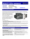
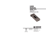
USER
MANUAL
MODEL 2701RC Series
NetLink-E1™
E1/Fractional E1 CSU/DSU
Rack Card
Part# 07M2701RC-B
Doc# 086131UB
Revised 03/09/01
CERTIFIED
An ISO-9001
Certified Company
SALES OFFICE
(301) 975-1000
TECHNICAL SUPPORT
(301) 975-1007
http://www.patton.com
TABLE OF CONTENTS
1.0 WARRANTY INFORMATION
Section
Page
1.0 Warranty Information .............................................................2
1.1 Warranty Statement
1.2 FCC Information
1.3 Service Information
2.0 General Information...............................................................4
2.1 Features
2.2 General Product Description
3.0 Configuration .........................................................................5
3.1 DIP Switch Configuration
3.3 Rear Interface Cards Configuration
4.0 Installation ..........................................................................34
4.1 The Model 1001R14 Rack Chassis
4.2 Installing the Interface Driver Board
4.3 Installing the 2701RC Into the Rack Chassis
4.4 Connecting to a DTE Device
4.5 Connecting to a DCE Device
4.6 Connecting the E1 Interface
4.7 Connecting dual Coax BNC (75ohm)
5.0 Operation .............................................................................36
5.1 LED Descriptions
5.2 Loop (V.54 & Telco) Diagnostics
5.3 Bit Error Rate (V.52) Diagnostics
Appendix A - Specifications ........................................................41
Appendix B - Cable Recommendations......................................42
Appendix C - Factory Replacement Parts and Accessories ......43
Appendix D - E1 Interface Pin Assignments ..............................44
Appendix E - DTE Interface Pin Assignments ............................45
Thank you for your purchase of this Patton Electronics product.
This product has been thoroughly inspected and tested and is warranted for One Year parts and labor. If any questions or problems arise
during installation or use of this product, please do not hesitate to contact Patton Electronics Technical Services at (301) 975-1007.
1.1 WARRANTY STATEMENT
Patton Electronics warrants all Model 2701RC Series components to be free from defects, and will at our option repair or replace
the product should it fail within one year from the first date of shipment.
This warranty is limited to defects in workmanship or materials, and
does not cover customer damage, abuse, or unauthorized modification.
This product contains no serviceable parts; therefore the user shall not
attempt to modify the unit in any way. If this product fails or does not
perform as warranted, your sole recourse shall be repair or replacement as described above. Under no condition shall Patton
Electronics be liable for any damages incurred by the use of this
product. These damages include, but are not limited to, the following:
lost profits, lost savings and incidental or consequential damages arising from the use of or inability to use this product. Patton Electronics
specifically disclaims all other warranties, expressed or implied, and
the installation or use of this product shall be deemed an acceptance
of these terms by the user. In the event the user detects intermittent or
continuous product malfunction due to nearby high power transmitting
radio frequency equipment, the user is strongly advised to use only
data cables with an external outer shield bonded to a metal or metalized connector.
1.2 FCC INFORMATION
This equipment has been tested and found to comply with the limits for a Class A digital device, pursuant to Part 15 of the FCC Rules.
These limits are designed to provide reasonable protection against
harmful interference when the equipment is operated in a commercial
environment. This equipment generates, uses, and can radiate radio
frequency energy and, if not installed and used in accordance with the
instruction manual, may cause harmful interference to radio communications. Operation of this equipment in a residential area is likely to
cause harmful interference in which case the user will be required to
correct the interference at his own expense. If this equipment does
1
2
cause harmful interference to radio or television reception, which can
be determined by turning the equipment off and on, the user is
encouraged to try to correct the interference by one or more of the following measures:
• Reorient or relocate the receiving antenna
• Increase the separation between the equipment and receiver
• Connect the equipment into an outlet on a circuit different from that
to which the receiver is connected
1.3 CE NOTICE
The CE symbol on your Patton Electronics equipment indicates
that it is in compliance with the Electromagnetic Compatibility (EMC)
directive of the European Union (EU). A Certificate of Compliance is
available by contacting Patton Electronics Technical Support.
1.4 SERVICE INFORMATION
All warranty and non-warranty repairs must be returned freight
prepaid and insured to Patton Electronics. All returns must have a
Return Materials Authorization number on the outside of the shipping
container. This number may be obtained from Patton Electronics
Technical Support at:
tel: (301) 975-1007
email: [email protected]
www: http://www.patton.com
NOTE: Packages received without an RMA number will not be
accepted.
Patton Electronics’ technical staff is also available to answer any
questions that might arise concerning the installation or use of your
Patton Model 2701RC. Technical Services hours: 8AM to 5PM EST,
Monday through Friday.
3
2.0 GENERAL INFORMATION
Thank you for your purchase of this Patton Electronics product.
This product has been thoroughly inspected and tested and is warranted for One Year parts and labor. If any questions arise during installation or use of the unit, contact Patton Electronics Technical Services at
(301) 975-1007.
2.1 FEATURES
•
•
•
•
•
•
•
•
•
•
•
•
•
Terminates E1/FE1 Circuits over a 4-Wire RJ-48C interface
Connects to standard CPE Serial Interfaces
Common Framed nx64 rates up to1984 kbps(G.704)
Unstructured Rate of 2.048 Mbps(G.703)
G.703 or G.704 Framing (with or without CRC-4, CAS multiframe)
Selectable AMI or HDB3 Line Coding
Configuration via Internal DIP Switches, software control port, or
SNMP management of local unit through the 1001MC
Six Easy-to-Read LED Indicators Monitor Data & Diagnostics
Internal, external, Network Clocking
Also Operates as a High-Speed Point-to-Point Modem
Fits into Patton’s 2U Rack-Mount Chassis
Made in USA
Conforms to ONP requirements CTR12 and CTR13 for connection to international telecom networks
2.2 GENERAL PRODUCT DESCRIPTION
The Model 2701RC Series are single port E1/FE1 CSU/DSUs that
provide high-speed WAN connectivity in a rack card package.
Connecting to the serial WAN port of a switch, router or multiplexer, the
NetLink-E1™ provides E1 or FE1 access connection at data rates of
2.048 Mbps and nx64. The Netlink-E1™ is an excellent choice when
terminating leased line services, Frame Relay backbones, internet
access as well as LAN-to-LAN services.
The Netlink-E1™ provides digital access to local WAN services
between two facilities over a dedicated 4-Wire circuit. WAN bandwidth, framing and coding options are programmed via internally
accessible DIP switches, via a VT-100 type terminal using a Model
1001CC control card, or SNMP managable through the 1001MC. With
a 1001CC card, a terminal can manage addressable 2701RC cards
using menu driven controls. The Netlink-E1™ uses AMI and HDB3 line
coding. Netlink-E1™ also supports a full range of system and diagnostic features that make system setup easy.
The NetLink-E1™ provides E1 terminations over a modular RJ-48C
jack or dual 75 Ohm BNC connectors when using the 1001RCM11575.
Power options include a single AC or DC or redundant AC/DC.
4
3.0 CONFIGURATION
The 2701RC features configuration capability via hardware DIP
switches, a software control port, or SNMP through the 1001MC. This
section describes all possible hardware and software switch configurations of the network connection.
NOTE: The 2701RC factory default is set to DIP switch control.
Software control can be enabled either through the control port
or SNMP management station. Performing a hardware reset sets
the unit for dip switch control.
3.1 DIP SWITCH CONFIGURATION
NOTE: If you do not have a terminal, you may force the unit to use the
DIP switches as the default configuration source by turning off the unit,
setting all the DIP switches to the ON position, then powering on the
unit. This will cause the unit to enter a special mode. Then turn off the
unit and change the switch settings to the desired settings. When you
turn the unit on again, the unit will be set up with the selected switch
settings.
NOTE: The Model 2701RC is set to HDB3 line coding at the
factory: This setting can be changed to AMI via VT-100 menus
(using the 1001CC card) or SNMP Management (using the
1001MC card).
The Model 2701RC has two eight bit DIP switches and two rotary
DIP switches that allow configuration for a wide range of applications.
The switches are accessed by removing the card from the chassis.
Switch S1-1 through S1-8
S3
S4
A detailed description of each switch (S1-1 through S1-8) setting follows the summary table below.
S1
SWITCH SET 1 SUMMARY TABLE
S2
Position
Function
S1-1
Addressing-100 s bit
Factory Default
OFF
Selected Option
Address 1-99
S1-2
Clocking Mode
OFF
Internal
S1-3
Clocking Mode
ON
Internal
S1-4
Data Rate
OFF
S1-5
Data Rate
OFF
S1-6
Data Rate
OFF
S1-7
Data Rate
OFF
S1-8
Data Rate
OFF
FRONT RS-530
Figure 1. Model 2701RC Series top view, showing location of DIP switches
Figure 1 (below) shows the location of the DIP switches on the top of
the printed circuit board.
DIP Switches S1 and S2 can be configured as either On or
Off . Figure 2 (below) shows the orientation of the DIP switches with
respect to ON/OFF positions. Default position and descriptions for
Switches S1 and S2 are provided on the next page.
}
Mbps Clear
Channel
SWITCH S1-1 ADDRESSING BIT
Use Switch S1-1 to select address range 100-120 when used in
conjunction with S3 and S4.
ON
S1-1
OFF
ON
Address
Address Range 1-99
Address range 100-120
OFF
Figure 2. Close up of DIP switches showing ON/OFF positions.
5
2.048
6
S1-2 and S1-3 CLOCK MODES
Set switch S1-2 and S1-3 to determine the 2701RC’s transmitter
timing.
S1-2
On
Off
On
Off
Network Clock
Internal Clock
External Clock
S1-3
On
On
Off
Off
Clock Mode
Network (Recieved Recovered)
Internal
External
Network (Recieved Recovered)
Transmitter timing is derived using the received line
signal (received recovered) from the network.
Transmitter timing is derived from an internal clock
source.
Transmitter timing is derived from DTE terminal tim
ing.
SWITCH S1-4 THROUGH S1-8: DTE DATA RATE
Use switches S1-4 through S1-8 to set the DTE data rate.
S1-4
ON
OFF
ON
OFF
ON
OFF
ON
OFF
ON
OFF
ON
OFF
ON
OFF
ON
OFF
ON
OFF
ON
OFF
ON
OFF
S1-5
OFF
ON
ON
OFF
OFF
ON
ON
OFF
OFF
ON
ON
OFF
OFF
ON
ON
OFF
OFF
ON
ON
OFF
OFF
ON
S1-6
OFF
OFF
OFF
ON
ON
ON
ON
OFF
OFF
OFF
OFF
ON
ON
ON
ON
OFF
OFF
OFF
OFF
ON
ON
ON
S1-7 S1-8
OFF OFF
OFF OFF
OFF OFF
OFF OFF
OFF OFF
OFF OFF
OFF OFF
ON
OFF
ON
OFF
ON
OFF
ON
OFF
ON
OFF
ON
OFF
ON
OFF
ON
OFF
OFF
ON
OFF
ON
OFF
ON
OFF
ON
OFF
ON
OFF
ON
OFF
ON
7
Speed
64kbps
128kbps
192kbps
256kbps
320kbps
384kbps
448kbps
512kbps
576kbps
640kbps
704kbps
768kbps
832kbps
896kbps
960kbps
1024kbps
1088kbps
1152kbps
1216kbps
1280kbps
1344kbps
1408kbps
ON
OFF
ON
OFF
ON
OFF
ON
OFF
ON
OFF
ON
OFF
OFF
ON
ON
OFF
OFF
ON
ON
OFF
ON
OFF
OFF
OFF
OFF
ON
ON
ON
ON
OFF
OFF
ON
ON
ON
ON
ON
ON
ON
ON
OFF
ON
ON
ON
ON
ON
ON
ON
ON
ON
OFF
1472kbps
1536kbps
1600kbps
1664kbps
1728kbps
1792kbps
1856kbps
1920kbps
1984kbps
Clear Channel 2048kbps
NOTE: When the data rate is set to 2.048Mb/s, the unit is forced
into G.703 mode, and it transmits user data on all 32 time-lots.
There is no framing information; therefore, the CRC4 MF (S2-2)
switch is ignored. In all other rate settings, the unit employs G.704
framing; TS0 is reserved for signaling.
SWITCH SET 2 SUMMARY TABLE
Position
Function
Factory Default
Selected Option
S2-1
CAS MF
OFF
Disabled
S2-2
CRC-4 multiframe
OFF
Disabled
S2-3
RDL Type
OFF
V.54
S2-4
RDL Response
ON
Enabled
S2-5
TM from DTE
ON
Enabled
S2-6
Front Panel Switch
ON
Enabled
S2-7
NMS/VT-100 Switch
OFF
VT-100
S2-8
Line build out
ON
120 Ohms
SWITCH S2-1: CAS MULTIFRAME
CAS multiframe uses Timeslot 16 (TS16) to send multiframe (MF)
alignment data. In CAS MF, a MF is defined as 16 frames, where a
frame consists of 32 64kb/s timeslots, numbered 0 to 31. TS16 of the
first frame in the MF contains the CAS MF alignment word in the upper
four bits. The alignment word is always 0000 (binary). The 2701RC
does not perform any signaling in TS16 other than to insert the MF
alignment word, in order to maintain MF alignment. When CAS MF disabled, the unit transmits user data in TS16; therefore, up to 31 channels are available for user data. When it is enabled, TS16 is not available to the user. In this case, the user can use up to 30 channels for
data. CAS MF can be used with CRC-4 MF or by itself. When enabled,
both units must employ CAS MF; if one unit is set for CAS MF, and the
other is not, the one using CAS MF will detect a loss of sync.
8
SWITCH S2-2: CRC-4 MULTIFRAME
In framed mode, S2-2 is used for CRC-4 MF. When CRC-4 is enabled,
the unit monitors the incoming data stream for CRC-4 errors. It transmits CRC-4 error counts to the transmitting unit.. When using timeslot
zero (TS0), excessive errors may cause loss of frame or loss of sync.
If CRC-4 MF is used, both units must be set for set for CRC-4 MF.
Otherwise, the one using CRC-4 MF will detect loss of sync.
Option
S2-2
Off
CRC-4 Disabled
On
CRC-4 Enabled
NOTE: When the data rate is set to 2.048Mb/s, then the unit is
forced into G.703 mode, and it transmits user data on all 32 timelots. There is no framing information; therefore, the CRC4 MF (S22) switch is ignored. In all other rate settings, the unit employs
G.704 framing; TS0 is reserved for signaling.
SWITCH S2-3: REMOTE DIGITAL LOOPBACK TYPE
The user can set this switch to select the type of remote loop that
will be initiated by the Model 2701. If set to V.54, the Model 2701 will
initiate a V.54 loop when Remote Loop is selected by the front panel
switches. If set to CSU, the Model 2701 will initiate a CSU loop when
Remote Loop is selected by the front panel switches.
RDL Type
S2-3
Off
Initiate a V.54 RDL loop when selected
On
Initiate a CSU loopback when selected
SWITCH S2-4: RDL RESPONSE
V.54 and CSU Loopbacks are special in-band loopback facility that
sends a pseudo-random pattern over the data stream. This is useful for
campus applications when you need to put a remote unit in loopback.
The unit responds to the V.54 loopback command, and the whole
process takes only a few seconds to complete. When V.54 Loopback
is disabled, the unit will not be able to send or respond to V.54 or CSU
loopback commands. The duration of the loopback is limited by the
loopback timeout setting.
S2-4
Option
Off
RDL Response Disabled
On
RDL Response Enabled
Off
On
Response to DTE Loopback Request Enabled
Response to DTE Loopback Request Disabled
SWITCH S2-6 FRONT PANEL SWITCHES
As the Front Panel Switches may be inadvertently toggled, or in the
event that the end-user may not need to use the switches, the installer
may disable the front panel switches. Set Switch S2-6 to determine
whether the front-panel toggle switches are enabled or disabled.
S2-6
Option
On
Front Panel Switches Enabled
Off
Front Panel Switches Disabled
SWITCH S2-7 VT-100 OR NMS SELECTION
Switch S2-7 selects the configuration mode that the G.703 Access
Rack Card uses. When VT-100 is selected, configuration and status
can be setup through a VT-100 terminal using a 1001CC. When NMS
(network management station) is selected, configuration and status
can be setup and maintained through SNMP using a 1001MC. Please
refer to the 1001MC user manual when using this mode.
Note: Dip switch configuration can be used regardless of the setting of
this switch. The dip switches are enabled through the VT-100 screens,
NMS, or by performing a hardware reset.
Management Selection
S2-7
On
NMS control
Off
VT-100 control
SWITCH S2-8 IMPEDANCE
Switch S2-8 is used to select the line build out for the Model 2701RC.
When using the 1001RCM11575 (dual BNC) rear card, set S2-8 to
OFF. When using a 120 Ohm cable with RJ-45 connectors, set S2-8 to
ON.
S2-8
Setting
75 Ohm
OFF
120 Ohm
ON
SWITCH S2-5 TEST MODE REQUEST FROM DTE
Use Switch S2-5 to allow Model 2701RC to enter loopback tests when
the DTE raises the appropriate loop request pin.
Setting
S1-8
9
10
3.2 CONFIGURING THE REAR INTERFACE CARD
The Model 2701RC Series has five interface card options: the
Model 1001RCM12548C (DB-25/RJ-48C), the Model
1001RCM13448C (M/34/RJ-48C), the Model 1001RCM11548C (DB15/RJ-48C), the Model 1001RCM11575 (DB-15/Dual BNC). Each of
these options supports one DTE interface connection and one 4-wire
line connection. Figure 3 below illustrates the five different interface
options for the Model 2701RC Series.
Model
1001RCM11575
Dual BNC
Model
Model
Model
1001RCM11548C 1001RCM12548C 1001RCM13448C
RJ-48C
RJ-48C
RJ-48C
Prior to installation, you will need to examine the rear card you
have selected and make sure it is properly configured for your application. Each rear card is configured by setting straps located on the PC
board. To configure the rear cards, you must set the configuration
straps. Figure 4 below shows the orientation of these straps. Each
strap can either be on pegs 1 and 2, or on pegs 2 and 3.
Model
IM2RC/IA
RJ-48C
Figure 4. Orientation of Interface Card Straps
Sections 3.2.1, 3.2.2, and 3.2.3 describe the strap locations and possible settings for each rear card.
3.2.1 Model 1001RCM12548C Strap Settings
Figure 5 shows strap locations for the Model 1001RCM12548C
(DB-25) rear cards. These straps determine various grounding characteristics for the terminal interface and twisted pair lines. JB3 and JB4
are user configurable.
DB-15 F
DB-15 F
DB-25 F
M/34 F
Figure 3. Model 2701RC Series interface card options
JB3
123
NOTE: The 2701RC Series rear cards are specifically designed
to operate with the E1 function card and must not be swapped
with other Patton function cards. In addition the rear card must
match the flip card installed on the front card.
JB4
123
Figure 5. 1001RCM125XX strap locations
11
12
The table below provides an overview of interface strap functions
for the rear interface cards. Following the table overview are detailed
descriptions of each strap’s function.
INTERFACE CARD STRAP SUMMARY TABLE #1
Strap
Function
Position 1&2
Position 2&3
JB3
DTE Shield (Pin1) & FRGND
Connected*
Open
JB4
FRGND & SGND
Connected*
Open
3.2.2 Model 1001RCM13448C Strap Settings
Figure 6 shows the strap location for the Model 1001RCM13448C
(M/34) rear card. This strap determines whether Signal Ground and
Frame Ground will be connected.
* Indicates default setting
JB3
123
DTE Shield (DB-25 Pin 1) & FRGND (JB3)
In the connected position, this strap links DB-25 pin 1 & frame
ground. In the open position, pin 1 is disconnected from frame ground.
JB3
Position 1&2 = DTE Shield (Pin 1) and FRGND Connected
Position 2&3 = DTE Shield (Pin 1) and FRGND Not Connected
JB4
123
Figure 6. 1001RCM13448C strap locations
SGND & FRGND (JB4)
In the connected position, this strap links DB-25 pin 7 (Signal
Ground) and frame ground through a 100 ohm resistor. In the open
position, pin 7 is connected directly to frame ground.
JB4
Position 1&2 = SGND (Pin 7) and FRGND Connected through
a 100 ohm resistor
Position 2&3 = SGND (Pin 7) and FRGND Directly Connected
The table below provides an overview of interface strap functions
for the rear interface cards. Following the table overview are detailed
descriptions of each strap’s function.
INTERFACE CARD STRAP SUMMARY TABLE #2
Strap
Function
Position 1&2
Position 2&3
JB3
DTE Shield (Pin A) & FRGND
Connected*
Open
JB4
FRGND & SGND (Pin B)
Connected*
Open
* Indicates default setting
DTE Shield (M/34 Pin A) & FRGND (JB3)
In the connected position, this strap links M/34 pin A & frame
ground. In the open position, pin A is disconnected from frame ground.
JB3
Position 1&2 = DTE Shield (Pin A) and FRGND Connected
Position 2&3 = DTE Shield (Pin A) and FRGND Not Connected
13
14
SGND & FRGND (JB4)
In the connected position, this strap links Signal Ground and frame
ground through a 100 ohm resistor. In the open position, signal ground
is disconnected from frame ground.
JB4
Position 1&2 = SGND and FRGND Connected
Position 2&3 = SGND and FRGND Not Connected
In the connected position, this strap links DB-15 pin 1 & frame
ground. In the open position, pin 1 is disconnected from frame ground.
JB3
Position 1&2 = DTE Shield (Pin 1) and FRGND Connected
Position 2&3 = DTE Shield (Pin 1) and FRGND Not Connected
SGND & FRGND (JB4)
3.2.3 Model 1001RCM11548C Strap Settings
Figure 7 shows strap locations for the Model 1001RCM11548C
(DB-15) rear cards. These straps determine various grounding characteristics for the terminal interface and twisted pair lines. JB3 and JB4
are user configurable.
The table below provides an overview of interface strap functions
In the connected position, this strap links DB-15 pin 8 (Signal
Ground) and frame ground through a 100 ohm resistor. In the open
position, pin 8 is connected directly to frame ground.
JB4
Position 1&2 = SGND (Pin 8) and FRGND Connected through
a 100 ohm resistor
Position 2&3 = SGND (Pin 8) and FRGND Directly Connected
3.2.4 Model 1001RCM11575 Strap Settings
Figure 8 shows strap locations for the Model 1001RCM11575 (DB15/Dual BNC) rear cards. Figure 8 shows strap locations for the Model
1001RCM11548C (DB-15) rear cards. These straps determine various
grounding characteristics for the terminal interface and twisted pair
lines. JB3 and JB4 are user configurable.
JB3
123
JB4
123
JB4 JB3
Figure 7. 1001RCM11548C strap locations
for the rear interface cards. Following the table overview are detailed
descriptions of each strap’s function.
INTERFACE CARD STRAP SUMMARY TABLE #3
Strap
Function
Position 1&2
Position 2&3
Figure 8. 1001RCM11575 strap locations
JB3
DTE Shield (Pin1) & FRGND
Connected*
Open
INTERFACE CARD STRAP SUMMARY TABLE #3
JB4
FRGND & SGND (Pin 8)
Connected*
Open
* Indicates default setting
DTE Shield (DB-15 Pin 1) & FRGND (JB3)
15
Strap
Function
Position 1&2
JB3
DTE Shield (Pin1) & FRGND
Connected*
Open
JB4
FRGND & SGND (Pin 8)
Connected*
Open
* Indicates default setting
16
Position 2&3
3.3 VT-100 SOFTWARE CONFIGURATION
3.3.2 Accessing the Menu System
This section describes the VT-100 configuration using a 1001CC.
For information on configuration using SNMP through the 1001MC,
please refer to the 1001MC user manual.
The NetLink-E1™rack card features a VT-100 menu-driven system
that may be used for local configuration and management. Cards are
configured and managed by setting a separate address for each card
using hardware switches and then accessing each card using a rack
mounted NetLink Model 1001CC control card. The software management system is described below. For more information on the Model
1001CC, please refer to the Model 1001CC user manual.
NOTE: The Model 1001CC uses an internal bus to communicate
with the 2701RC. When using software configuration, the rear
card for the 2701RC should be configured with FRGND and
SGND connected. Please see section 3.2 for more information
on configuring your rear card.
1)
Set the Card Address as described in Section 3.2.1.
2)
Set S2-7 to the OFF position to select VT-100 control.
3)
Power up the terminal and set its RS-232 port as follows:
9600 Baud
8 data bits, 1 stop bit, no parity
Local echo off
ANSI or VT-100 emulation
4)
Here is an example of a terminal emulator setup session. In
normal font are the various parameter types. In bold type are
the values that should be used for best results. Your terminal
program’s setup screen may differ from this one:
3.3.1 Setting the Card Address
Baud rate: 9600
The 2701RC contains two rotary switches (S3 and S4) which are used
to set the address of the card. Figure 8, below, shows a close-up of
S3 and S4 and the addressable digits.
456
456
78
0
9
78
9
1
0
2 3
S4
2 3
S3
Parity: None
Data Length: 8
Default terminal type:
Local Echo:
Add Line Feeds after CRs:
Received Backspace Destructive:
Backspace key sends:
XON/XOFF software flow control:
CTS/RTS hardware flow control:
DSR/DTR hardware flow control:
Stop Bits: 1
VT-100
Off
Off
On
BS
On
Off
Off
1
Figure 8. Close-Up of Switches S3 and S4
Switches S3 and S4: Card Address
5)
Install the 2701RC and the 1001CC Control Card into the rack
system (see Section 4.0 Installation, page 32, to install the
2701RC; see the 1001CC User Manual to Install the Model
1001CC Card and to connect the RS-232 port).
6)
After your 2701RC units are installed and you have set up
your Model 1001CC and VT-100 terminal as described above,
you are ready to access the 2701RC cards. This is done by
selecting the address for a card using the command “Ctrl-b”
address <CR>. For example, if your 2701RC has an address
of “64”, type the following:
Switches S3 and S4 are used to set the address of the card.
Switch S4 is the tens place digit and S3 is the ones place digit.
Following are examples of address settings (Default Address= “00”)
S4
0
5
8
S3
4
2
6
RDL Type
Card Address = 04
Card Address = 52
Card Address = 86
Ctrl b (Hold down the Ctrl key and depress the b character)
64 (Type in the address 64 )
<CR> (Depress the Enter/Carriage Return key)
17
18
The password prompt will be displayed as shown below.
3.3.3 Introduction to Main Menu
After entering the password, you may access all of the system’s
functions and parameters. The Main Menu looks like this:
Patton Electronics
Menu Management
Enter Password: _
.
6)
Note: The password is case sensitive. Type the password
and press <Enter>. The factory default password for the unit
is:
patton
NOTE: If the entry is incorrect, the password screen will clear
and prompt you again for the correct password. The password
you enter will not be shown. For security, asterisks will be displayed for each letter you type. The maximum length of the
password, which can include any character the terminal can
generate, is 16 characters.
7)
The NetLink-E1™ will then display the Main Menu screen.
19
2701RC
HELPFUL HINTS
1.
To make a selection, key the highlighted letter that corresponds to a menu selection.
2.
To execute the selection, type [Enter/CR].
3.
To toggle between options on a highlighted selection, Press
[space].
4.
Select gd Save Changes from Main Menu after making modifications to any Model 2701RC parameter. Otherwise,
changes will be lost when the Model 2701RC is turned off.
20
3.3.4 System Configuration
The Main Menu options are briefly described below.
The System Configuration menu looks like this:
a
System Configuration options allow you to change various
aspects of the Model 2701RC operation, e.g., framing, line
coding, and aggregate bandwidth.
b
System Diagnostics/Statistics options allow you to monitor
the network performance, initiate V.54 loops, local loops, and
send test patterns. Network performance parameters are
updated once a second, giving you the ability to quickly determine if there is a problem.
c
Unit Options allow you to customize the Model 2701RC for
your location. You can change the default header names to
give each unit a unique name and password. Also, you can
reset the unit to its default settings without the manual. It also
has a Service Information screen in case you need technical
assistance from Patton.
d
Save Changes Once you have configured the unit to your
satisfaction, you can save the changes permanently by executing the Save Changes command. This will update the unit’s
configuration and save all the parameters to permanent memory.
e
Logoff For security, log off the control menu by executing the
Logoff command. This will blank the screen until an [Enter]
key is pressed.
The System Configuration options are described below:
a
Line Format: G.703 (default)
Options: G.703, G.704
G.703: G.703 is unframed, 2.048Mb/s. In this case, the DTE rate
is equal to the line rate at the network interface (NI). CAS MF
and CRC-4 are disabled.
G.704: G.704 reserves TS0 for signaling and frame alignment.
Maximum data rate depends on whether CAS MF is enabled
or not.
21
22
b
Line Coding: HDB3 (default)
d
Clocking: Network (default)
Options: AMI, HDB3
Options:
HDB3: In this line coding, the transmitter substitutes a deliberate
bipolar violation when excessive zeros in the data stream are
detected. The receiver recognizes these special violations and
decodes them as zeros. This method enables the network to
meet minimum pulse density requirements. Unless AMI is
required in your application, HDB3 should be used whenever
possible.
Network: This is the most commonly used setting when connecting to a carrier’s network. In this mode, the unit recovers the
clock from the received signal and uses it to transmit data. In
this way the unit remains synchronized to a master clock. In
campus applications, one of the units must be set to Internal
clock, and the other end is set to Network clock. At all times,
there must be only one clock source. Otherwise, clock slips
and framing errors and bit errors may occur.
AMI: Alternate Mark Inversion defines a pulse as a "mark,” a
binary one, as opposed to a zero. In a E1 network connection,
signals are transmitted as a sequence of ones and zeros.
Ones are sent as pulses, and zeros are sent as spaces, i.e.,
no pulse. Every other pulse is inverted from the previous
pulse in polarity, so that the signal can be effectively transmitted. This means, however, that a long sequence of zeros in
the data stream will cause problems, since the NTU receiving
the signal relies on the signal to recover the 2.048 Mb/s clock.
If you must use AMI, you should ensure that the data terminal
equipment connected to the unit provides a minimally acceptable pulse density. For this reason, there are advantages to
using HDB3 instead.
Network, Internal, External
Internal: This is commonly used in campus applications, where
the unit is not connected to the public telephone network
directly. In this mode, the unit uses the on-board oscillator as
the transmit clock source.
External: In this mode, the unit requires a clock signal from the
DTE via the external clock pin on the DTE interface connector. Most applications will use Network or Internal clock
modes.
e
Line Build Out: 120 Ohm (default)
Options: 120 Ohm, 75 Ohm
120 Ohm: Use with 120 Ohm RJ-48C connector.
75 Ohm: Use with the 1001RCM11575 rear card. (Dual BNC
connectors)
f
CRC-4 Setting: Disabled (default)
Options: Enabled, Disabled
CRC-4 Multiframe: CRC-4 Multiframe uses TS0 to carry CRC-4
information. It operates independently of CAS MF. When
CRC-4 is enabled, the unit monitors the incoming data stream
for CRC-4 errors. It transmits CRC-4 error counts to the transmitting unit . Excessive errors may cause loss of frame or loss
of sync. If CRC-4 MF is used, both units must be set for CRC4 MF; otherwise, the one using CRC-4 MF will detect a loss of
sync.
23
24
CAS MF Setting: Disabled (default)
Options: Enabled, Disabled
g
i
CAS MF: CAS multiframe uses Timeslot 16 (TS16) to send multiframe (MF) alignment data. In CAS MF, a MF is defined as 16
frames, where a frame consists of 32 64kb/s timeslots, numbered 0 to 31. TS16 of the first frame in the MF contains the
CAS MF alignment word in the upper four bits. The alignment
word is always 0000 (binary). The 2715 does not perform any
signaling in TS16 other than to insert the MF alignment word,
in order to maintain MF alignment. When CAS MF disabled,
the unit transmits user data in TS16; therefore, up to 31 channels are available for user data. When it is enabled, TS16 is
not available to the user. In this case, the user can use up to
30 channels for data. CAS MF can be used with CRC-4 MF or
by itself. When enabled, both units must employ CAS MF; if
one unit is set for CAS MF, and the other is not, the one using
CAS MF will detect a loss of sync.
NOTE: If you do not have a terminal, you may force the unit to use the
DIP switches as the default configuration source by turning off the unit,
setting all the DIP switches to the ON position, then powering on the
unit. This will cause the unit to enter a special mode. Then turn off the
unit and change the switch settings to the desired settings. When you
turn the unit on again, the unit will be set up with the selected switch
settings.
n
DS0 Channel Configuration Menu [ Bandwidth/# Channels =
2,048k/na] (default)
The Channel Configuration Menu has a sub-menu that looks
like this:
V.54 Loops: Enabled (default)
Options: Enabled, Disabled
This is a special in-band loopback facility that sends a special pseudorandom pattern over the data stream. This is the only loopback that the
unit can initiate. This is useful for campus applications when you need
to put a remote unit in loopback. The unit responds to the V.54 loopback command, and the whole process takes only a few seconds to
complete. When V.54 Loopback is disabled, the unit will not be able to
send or respond to V.54 loopback commands. The duration of the loopback is limited by the loopback timeout setting. While V.54 is being
activated, user data is overwritten.
j
Default Config Source: Switch (default)
Options: EEPROM, Switch
The Model 2701RC can be initialized via the configuration in the onboard permanent memory (EEPROM) or via the internal DIP switches
(Switch). Once the unit is powered up, you may change the settings
through the control port or the DIP switches. When you make changes
through the control port, no changes will take place or be saved to permanent memory until you Save Changes (Main Menu option "d" +
[Enter]). When you make changes through the switches, all changes
are made immediately.
25
2701RC
You may configure the Model 2701RC to operate with any combination
of active and inactive DS0 channels in this screen. When you execute
the Save Changes command, the selected settings will be saved to
permanent memory, and the system will be updated to operate with the
new channel settings.
NOTE: In Unframed format, the Bandwidth Selected will display
“2.048k,” and the Total Channels will display “na.” When using the
DIP switches to set the bandwidth, the starting channel is always
channel 1 or 0.
26
Front Panel Switches: enabled (default)
The Local Loop test has four states:
Options: enabled, disabled
As the Front Panel Switches may be inadvertently toggled, or in the
event that the end-user may not need to use the switches, the installer
may disable the front panel switches. Set Switch S2-6 to determine
whether the front-panel toggle switches are enabled or disabled.
S2-6
On
Off
Option
Front Panel Switches Enabled
Front Panel Switches Disabled
b
3.2.3 System Diagnostics
The System Diagnostics/Statistics screen looks like this:
Idle
No user-controlled loopbacks are active.
LL
The Model 2701RC is in local loopback mode.
Off
The Model 2701RC is in remote loopback mode or sending a pattern. Local loopback is disabled.
LocP
The Model 2701RC is in Local Loopback mode, and is
sending a test pattern.
Remote Loop Idle (default)
The Remote Digital Loopback (RDL) test checks the performance
of both the local and remote Model 2701RCs, as well as the communication link between them. Data from the local DTE is sent across the
entire communication circuit and looped back to the local DTE.
The Model 2701RC Initiating a RL can be in one of the following
states:
Idle
No user-controlled loopbacks are active.
TxPr
The Model 2701RC is sending the preparatory phase pattern lasting for approximately 2 -5 seconds.
WtAk
The Model 2701RC is waiting for an acknowledgement
from the remote unit. If the remote unit does not
respond, the WtAk message will remain on the screen.
RxAk
The Model 2701RC has received an acknowledgement
from the remote unit.
Tout
The Model 2701RC is waiting before entering the Remote
Loopback test mode.
TM
The System Diagnostics/Statistics options and functions are described
below.
The Model 2701RC has successfully negotiated the
Remote Loopback test and is in control of the remote
unit. You may send a test pattern at this point by pressing:
a
d <spacebar>
NOTE: This screen is updated once per second.
Local Loop Idle (default)
The Local Loop is a bi-lateral loopback in which the data from the local
DTE and the data from the remote unit are looped back to their respective sources (See Section 5.3). Activate this loop to test the each of
the DTE’s connection to the Model 2701RC.
27
TxTr
The Model 2701RC is sending a Terminate Loopback
message to the remote unit. If the remote unit does not
respond, the local unit will return to the Idle state.
28
Tx1s
TxP
IdlP
If the remote Model 2701RC responds to the local Model
2701RCs terminate loopback request, the local unit then
sends an all ones pattern before returning to the Idle
state
The Model 2701RC is sending a test pattern while in Test
Mode
The Model 2701RC is sending a test pattern in place of
data. The Model 2701RC is not in test mode.
d
Test Pattern Idle (default)
Options: Idle or Sending
To send a pattern, press the ‘c’ key and press <spacebar> to send the
test pattern. The “OK” message indicates the received test pattern is
error-free. The “BE” message indicates errors in the received pattern.
You may also hear a beep (from your termainal) once a second as long
as the unit detects a bit error in the pattern.
The Model 2701RC receiving a RL can be in one of the following
states:
Idle
Indicates that Model 2701RC is not sending a pattern.
Sending
RxPr
The Model 2701RC is receiving a preparatory pattern.
Sack
The Model 2701RC, upon receiving a preparatory pattern, sends an acknowledgement message.
RL
The Model 2701RC is in remote loopback mode.
RxTr
The Model 2701RC is receiving a terminate loopback
message.
WE1s
The Model 2701RC is waiting for a sequence of all ones
and will time out if it does not receive it.
Indicates that Model 2701RC is sending a pattern.
e
Error Insertion Off (default)
Options: On, Off
You may inject intentional errors into the test pattern by turning Error
Insertion ON. The Error (ERR) LED will blink once per second.
f
IdleP
The Model 2701RC is sending a QRSS, 511 or 2047 pattern.
Off
The Model 2701RC is in local loopback.
Selected Pattern
Options: QRSS, 511, or 2047
Use this option to select the test pattern used to test the link.
NI STATUS
c
The Network interface (NI) status is shown in the middle of the
Diagnostics/Statistics screen. The brackets
are empty when the link is operating normally. Only one error message is provided.
RDL Type: V.54 (default)
Options: V.54 or CSU
The user can set this switch to select the type of remote loop that
will be initiated by the Model 2701. If set to V.54, the Model 2701 will
initiate a V.54 loop when Remote Loop is selected by the front panel
switches. If set to CSU, the Model 2701 will initiate a CSU loop when
Remote Loop is selected by the front panel switches.
S2-3
RDL Type
Off
Initiate a V.54 RDL loop when selected
On
Initiate a CSU loopback when selected
Receiver Carrier Loss [RCL] occurs when
255 consecutive zeros have been detected
at the network interface. RCL clears when a
pulse is detected.
Current DIP Switch Settings
The Switch settings are displayed here to
facilitate troubleshooting your unit without
opening up the unit first.
29
30
d
3.2.4 Unit Options
The Unit Options screen looks like this (factory default):
Loop Timeout
The Loop Timeout setting can be set to one of the following:
00:05 =
00:10 =
00:15 =
00:30 =
00:45 =
01:00 =
01:30 =
02:00 =
03:00 =
NEVER =
e
five minutes
ten minutes
fifteen minutes
thirty minutes (default setting)
forty-five minutes
one hour
90 minutes
two hours
three hours
forever—the unit will remain in loopback without user
intervention.
Tx Data Clock: Internal Tx Clock (default)
Options: Internal Tx Clock or External Tx Clock
a
Header Line 1 &
b
Header Line 2
Headers 1 and 2 are provided for easy identification of your unit after
installation. You may want to give each unit a unique name via the
header lines to help distinguish one unit from another. You can enter a
header up to 40 letters long. Two lines provide 80 letters for your use.
That’s a lot of flexibility!
Password
The Password facility provides security by allowing only those who
know the correct password to configure the unit via the control port.
You can still configure the unit via the DIP switches. The password can
be up to 16 characters long, with no restriction on the combination of
characters you can use, so be sure to remember the password. The
password is case sensitive. If you lose your password, you will lose the
ability to access the unit via the control port.
31
Switch S2-7 selects the clock that is used to accept the Transmit Data
from the DTE interface. Standard DTE interfaces will transmit data with
respect to the External Clock. In some cases a DTE interface will
transmit with respect to the Transmit clock sent out from the 2701RC.
Please review the information provided with your DTE equipment for
more information on its' operation. In most cases when there are errors
on the line only in the direction of the transmit data, S2-7 can be
changed to solve the problem.
Tx Clock Select
S2-7
Off
Transmit data accept with respect to the transmit
clock from the 2701RC
On
Transmit data accept with respect to the external
clock from the DTE
f
Set to Default Configuration
You may set the Model 2701RC to its factory default configuration,
except for the header lines and the password, by executing the Set to
Default Configuration command.
32
4.0 INSTALLATION
f
Service Information
If you need to contact us for help, you can view the Service Information
screen. Here is what it looks like:
This section describes the functions of the Model 1001R14 rack
chassis, tells how to install front and rear Model 2701RC Series cards
into the chassis, and how to connect to the twisted pair interface and
the serial interface.
4.1 THE MODEL 1001R14 RACK CHASSIS
The Model 1001R14 Rack Chassis (Figure 9, below) has fourteen
or sixteen device card slots, plus a single power supply or dual redundant power supplies. Measuring only 3.5 high, the Model 1001R14 is
designed to occupy only 2U in a 19 rack. Sturdy front handles allow
the Model 1001R14 to be extracted and transported conveniently.
2701RC
Figure 9. Model 1001R14 Rack Chassis with power supply
4.1.1 The Rack Power Supply
The power supply included in the Model 1001R14 rack uses the
same mid-plane architecture as the modem cards. The front card of
the power supply slides in from the front, and the rear card slides in
from the rear. They plug into one another in the middle of the rack.
The front card is then secured by thumb screws and the rear card by
conventional metal screws.
WARNING! There are no user-servicable parts in the
power supply section of the Model 1001R14 rack. Voltage
setting changes and fuse replacement should only be performed by qualified service personnel. Contact Patton
Electronics Technical Support at (301)975-1000 for more
information.
33
34
Powering up Your 1001R14 Rack
The power supplies that come with your 1001R14 rack system are
equipped with a power entry connector on the rear power supply card.
The power supplies are Hot-Swappable, so you are not required to
remove the cards from the rack while applying power to the system.
NOTE: Please refer to the Model 1001R14 Series User Manual
AC and DC Rack Mount Power Supplies for fuse and power card
replacement information.
3.
Locate the correct interface on the bottom of the driver board.
For example, the RS-232/V.35 interface board is marked
THIS SIDE UP FOR V.35 on one side and THIS SIDE UP
FOR RS-232 on the other side. Other single interface
boards (e.g. RS-530) are marked with the with FRONT on
one side of the board.
4.
Re-orient the interface board into the socket with the appropriate interface pointed UP and with the arrow pointing toward
the front panel of the Model 2701RC pc board.
5.
Push the Interface Driver Board gently onto the socket and reinstall into the 1001 rack.
4.2 INSTALLING THE INTERFACE DRIVER BOARD
The DTE electrical interface on the 2701RC is determined by a
DTE daughter board that is mounted on the main board by a 20 pin
jumper. Figure 10 shows the Interface Driver Board on the top of the
2701RC main board.
4.3 INSTALLING THE MODEL 2701RC INTO THE CHASSIS
The Model 2701RC is comprised of a front card and a rear card.
The two cards meet inside the rack chassis and plug into each other
by way of mating 50 pin card edge connectors. Use the following
steps as a guideline for installing each Model 2701RC into the rack
chassis:
Interface Driver
Board
FRONT RS-530
Figure 10. Interface Driver Board
1.
Slide the rear card into the back of the chassis along the
metal rails provided.
2.
Secure the rear card using the metal screws provided.
3.
Slide the card into the front of the chassis. It should meet the
rear card when it s almost all the way into the chassis.
4.
Push the front card gently into the card-edge receptacle of the
rear card. It should click into place.
5.
Secure the front card using the thumb screws.
NOTE: Since the Model 1001R14 chassis allows hot swapping
of cards, it is not necessary to power down the rack when you
install or remove a Model 2701RC.
Follow the instructions below to install or change the correct interface for your application.
4.4 CONNECTING TO A DTE DEVICE
1.
2.
With the 2701RC front card pulled out of the rack chassis,
locate the driver board on top of the 2701RC front card.
Lift the interface drive board gently off the main PC board.
35
The serial port on most rear interface cards are hard-wired as
DCE (Data Circuit Terminating Equipment). The interfaces are
designed to plug into a DTE such as a terminal, PC or host computer.
When making the connection to your DTE device, use a straight
through cable of the shortest possible length--we recommend 6 feet or
less. When purchasing or constructing an interface cable, please refer
to the pin diagrams in Appendix D and Appendix E as guides.
36
5.0 OPERATION
4.5 CONNECTING TO A DCE DEVICE
The rear interface cards on most interface modules are hard wired
as DCE . Therefore, you must use a null modem cable when connecting to a modem, multiplexer or other DCE device. This cable
should be of the shortest possible length--we recommend 6 feet or
less. When purchasing or constructing a null modem interface cable,
use the pin diagrams in Appendix C as a guide.
NOTE: Pin-out requirements for null modem applications
vary between equipment manufacturers. If you have any
questions about a specific installation, please contact Patton
Electronics Technical Support.
Once the NetLink-E1™ is installed and configured properly it is
ready to place into operation. This section describes the function of
the LED indicators, and the use of the loopback and pattern test
modes.
5.1 LED DESCRIPTIONS
The NetLink-E1™ is equipped with nine LED indicators that monitor
the status of communication. Figure 12 (below) shows the location of
the LEDs on the NetLink-E1™ Series front panel.
4.6 CONNECTING THE E1 INTERFACE
Model 2701RC
The Network Line Interface is an eight position keyed modular jack
configured as a RJ-48C. This interface will need to be configured to
match the line parameters (i.e. framing, line coding, etc.) supplied by
the central office.
1
2
3
4
5
6
7
8
Figure 11.
1 RX Data (TIP)
2 RX Data (RING)
3 (no connection)
4 TX Data (TIP)
5 TX Data (RING)
6 (no connection)
7 (no connection)
8 (no connection)
}
From Network
Figure 12. Model 2701RC front panel, showing LED indicators.
}
To Network
TXD
When the unit sends a one, the TXD LED is
green. When it sends a zero, the TXD LED
is yellow. Moreover, the TXD LED is active
only in active DS0 channels. In inactive
channels, the TXD LED is off.
RXD
When the unit receives a one, the RXD LED
is green. When it receives a zero, the RXD
LED is yellow. Moreover, the RXD LED is
active only in active DS0 channels. In inactive channels, the RXD LED is off.
LOS
The Loss of Sync LED lights when the unit
loses synchronization with the incoming signal. This may happen when there is a framing mismatch or a loss of signal. In
unframed mode, the LOS LED monitors the
NOTE: If the
NetLink-E1“ twisted pair line interface.
NetLink-E1“ is being used for private short range modem applications, the twisted pair cable connected to its port will need to be
a cross-over cable. See Appendix D for Interface pin assignments.
4.7 CONNECTING DUAL COAX BNC (75 OHM)
In addition to the 120 Ohm twisted pair connection, the Model
2701RC, when used with the 1001RCM11575 rear card, is equipped
with dual female BNCs (TX and RX) for connection to a 75 ohm dual
coax G.703 network interface.
37
38
status of the transmit clock.
5.2 LOOP (V.54 & TELCO) DIAGNOSTICS
ALM
The alarm LED indicates the presence of a
Blue or Yellow Alarm, or Out of Frame condition. The ALM LED will blink on every halfsecond. Alarms may occur due to:
• Loss of Synchronization
• Loss of Frame
• AIS (Blue Alarm)
• RAI (Yellow Alarm)
ERR
TST
The error LED indicates various error conditions, including framing bit errors, excessive
zeros, controlled slips, severe errors, or bit
errors (when sending V.52 test patterns).
When sending a test pattern, the LED will
remain lit if the unit does not receive the
identical pattern. When it receives the correct pattern, the LED will turn off. If error
insertion is on, the LED will blink once a
second if everything is operating properly.
The test indicator LED blinks with a specific
pattern depending on the type of test mode.
When the unit is in local analog loop, the
LED will blink on briefly. When the unit is in
remote loop, the TST LED will blink off
briefly. When the unit is sending a test pattern or is putting the remote unit into
V.54/CSU loopback, the TST LED will stay
on. These are the test modes:
• V.54/CSU Loopback & V.52 Patterns
• Local Loopback
PWR
The NetLink-E1™ offers three V.54 loop diagnostics and is compatible with two Telco loop diagnostics. Use these diagnostics to test
the CSU/DSU and any communication links. These tests can be activated via the software control port (See Section 3.2.3 System
Diagnostics), via signals on the serial port interface or the front panel
switch.
5.2.1 Operating Local Loopback (LL)
The Local Loopback (LL) test checks the operation of the local
NetLink-E1™, and is performed separately on each unit. Any data
sent to the local NetLink-E1™ in this test mode will be echoed
(returned) back to the user device (i.e., characters typed on the keyboard of a terminal will appear on the terminal screen).
Receive
Recover
Clocking
Internal
Clocking
Serial
Device
Cable Span
Clock/
Data
Data
Serial
Device
Clock/
Data
Data
Clock/
Data
Model 2701 RC
LLB Initiated
Model 2701RC
Figure 7. Local Loopback
To perform a LL test, follow these steps:
1.
Activate LL. This may be done in one of three ways:
a.
Enter a Local Loop from the System
Diagnostics/Statistics menu and toggle the <Spacebar>
until LL appears next to the a Local Loop option.
b.
Activate the LL signal on the DTE. If you are not sure
which lead is the LL signal, please refer to Appendix D.
c.
Toggle the front panel switch to the Local position.
The power indicator LED will remain lit while
the unit is powered. It turns off when the
unit is not powered.
39
G.703/G.704 NTU
Model 2701 RC
G.703/G.704 NTU
Model 2701 RC
40
2.
3.
Verify that the data terminal equipment is operating properly
and can be used for a test.
Perform a V.52 BER (bit error rate) test as described in
Section 5.3. If the BER test equipment indicates no faults,
but the data terminal indicates a fault, follow the manufacturer s checkout procedures for the data terminal. Also, check
the interface cable between the terminal and the NetLink-E1.
2.
5.2.2 Operating Remote Digital Loopback (RL)
The Remote Digital Loopback (RL) test checks the performance of
both the local and remote NetLink-E1™, as well as the communication
link between them. Any characters sent to the remote NetLink-E1™ in
this test mode will be returned back to the originating device (i.e, characters typed on the keyboard of the local terminal will appear on the
local terminal screen after having been passed to the remote NetLinkE1™ and looped back).
G.703/G.704 NTU
Model 2701 RC
G.703/G.704 NTU
Model 2701 RC
Receive
Recover
Clocking
Internal
Clocking
Serial
Device
Cable Span
Clock/
Data
Data
Ethernet
Device
Clock/
Data
Data
Clock/
Data
Model 2701RC
RDL Initiated
Model 2701RC
Figure 8. Remote Loopback
There are two Remote Loops that can be initiated from the
NetLink-E1 unit: (1) V.54 Loop, and; (2)CSU Loop. The user can
select the type of loop that can be initiated from the System
Diagnostics/Statistics screen or with Switch S2-1. Select c RDL
Type and press the <spacebar> to toggle between the CSU loop and
the V.54 loop. When a loopback is initiated this is the type of loop that
the unit uses to loop up the remote unit. NOTE: The NetLink-E1 will
respond to both loops regardless of the state of the RDL Type.
b.
Activate the RL signal on the DTE. If you are not sure
which lead is the RL signal, please refer to Appendix D.
c.
Set the front panel switch to Remote .
Perform a bit error rate test (BERT) using the internal V.52
generator (as described in Section 5.3), or using a separate
BER Tester. If the BER test indicates a fault, and the Local
Line Loopback test was successful for both NetLink“s, you
may have a problem with the twisted pair line connection.
5.2.3 CSU Loop
The NetLink-E1“ also responds to central office initiated loop commands. The NetLink-E1“ will implement the loop up command
when it recognizes the pattern 10000 in the data stream for a minimum of 5 seconds. The loop down command is implemented by the
pattern 100 in the data stream for a minimum of 5 seconds.
The NetLink-E1™ will respond to Universal Loopback De-activate
to clear all central office loops.
5.3 BIT ERROR RATE (V.52) DIAGNOSTICS
The NetLink-E1™ offers three V.52 Bit Error Rate (BER) test patterns. These test patterns may be invoked along with the LAL and
RDL tests to evaluate the unit(s) and the communication links.
When a 511, 2047, or QRSS test is invoked, the NetLink-E1™ gen20
erates a pseudo-random bit pattern of 511 bits, 2047 bits or 2 bits,
respectively, using a mathematical polynomial. The receiving NetLinkE1™ then decodes the received bits using the same polynomial. If the
received bits match the agreed upon pseudo-random pattern, then the
NetLink-E1™(s) and the communication link(s) are functioning properly.
511
Initiates a built-in 511 bit pseudo-random
pattern generator and detector.
2047
Initiates a built-in 2047 bit pseudo-random
pattern generator and detector.
QRSS
Initiates a built-in 2 bit pseudo-random
pattern generator and detector.
To perform an RDL test, follow these steps:
1.
Activate RDL. This may be done in three ways:
a.
Enter b Remote Loop from the System
Diagnostics/Statistics menu and toggle the <Spacebar>
until RL appears next to the b Remote Loop option.;
41
20
42
APPENDIX A
To perform a V.52 test, follow these steps:
1.
Activate the local loopback or remote loopback diagnostic.
PATTON MODEL 2701RC
2.
Activate the test pattern. This may be done in one of two
ways:
SPECIFICATIONS
a.
Enter c Test Pattern from the System
Diagnostics/Statistics menu and toggle the <Spacebar>
until the desired test pattern appears.
One of two result codes will appear to the right of the
c Test Pattern listing:
OK Indicates that the received test pattern is error-free.
b.
Network Data Rate:
2.048 Mbps
Network Connector:
RJ-48C or dual BNC
Nominal Impedance:
120 ohm (75 ohm available when using
Patton Model 1001RCM11575 rear
card)
DTE Interface:
V.35 (DCE Orientation) X.21 (DCE or
DTE orientation), RS-530, RS-232,
10Base-T, Ethernet
Line Coding:
Selectable AMI or HDB3
BE Indicates that there are errors in the test pattern (to
deliberately insert errors in the pattern, toggle
d Error Insertion to ON).
Line Framing:
G.703 (Unframed) or G.704/G.732
(Framed)
CAS Multiframing:
Selectable On or Off
Toggle the front panel switch to either PAT or PAT/E (Test
Pattern with Error Injection).
CRC-4 Multiframing:
Selectable On or Off
Clocking:
Internal, External, or Receive Recover
DTE Data Rates:
64, 128, 192, 256, 320,384, 448, 512,
576, 640, 704, 768, 832, 896, 960,
1024, 1088, 1152, 1216, 1280, 1344,
1408, 1472, 1536, 1600, 1664, 1728,
1792, 1856, 1920, 1984, 2048 kbps
Time Slot Rate:
64 kbps
DS0 Start Position:
Arbitrary
DS0 Mapping Position:
Contiguous or Arbitrary
Diagnostics:
V.54 Loopback; V.52 Patterns: 511,
2047, and QRSS
Indicators:
Power, Transmit Data, Receive Data,
Alarm, Loss of Sync, Test Mode, Error
Configuration:
Two 8-Position DIP Switches, RS-232
Control Port, or SNMP Managable
Power Supply:
100-240VAC, 50-60Hz, 0.4A
Humidity:
Up to 90% non-condensing
Temperature:
0 to 70o C
Dimensions:
9.0 x 5.3 x 2.0 cm (3.5”L x 2.1”W x
0.78”H)
43
44
APPENDIX C
APPENDIX B
PATTON NETLINK-E1™ MODEL 2701RC
CABLE RECOMMENDATIONS
The Patton NetLink E1™ Series has been performance tested by
Patton technicians using twisted-pair cable with the following characteristics:
Wire Gauge
Capacitance
Resistance
19 AWG
22 AWG
24 AWG
83nf/mi or 15.72 pf/ft.
83nf/mi or 15.72 pf/ft.
83nf/mi or 15.72 pf/ft.
.0163 Ohms/ft.
.0326 Ohms/ft.
.05165 Ohms/ft.
To gain optimum performance from the Model 2701RC Series,
please keep the following guidelines in mind:
• Always use twisted pair wire—this is not an option.
• Use twisted pair wire with a capacitance of 20pf/ft or less.
• Avoid twisted pair wire thinner than 26 AWG (i.e. avoid AWG
numbers higher than 26)
• Use of twisted pair with a resistance greater than the above
specifications may cause a reduction in maximum distance obtainable. Functionality should not be affected.
• Many environmental factors can affect the maximum distance
obtainable at a particular site.
45
PATTON NETLINK-E1™ MODEL 2701RC
FACTORY REPLACEMENT PARTS
AND ACCESSORIES
Description
Patton Model #
2701RC/D/V........................E1/FE1 CSU/DSU Rack Card, X.21
Interface w/DB15FS/RJ48C rear card
2701RC/B/B ........................E1/FE1 CSU/DSU Rack Card, RS530\
Interface with DB25F/RJ48C Rear
Card
2701RC/A/I ..........................E1/FE1 CSU/DSU Rack Card, V.35
Interface with M/34F/RJ48C Rear Card
1001RPEM-RAC
120/240V Rear Power Entry Module
1001RPEM-RAC
120/240V Rear Power Entry Module
1001RPSM-RUI...................120/240V Front Power Supply Module
1001RPEM-RDC.................DC Rear Power Entry Module
1001RPSM-R48A................48V Front Power Supply Module
1001R14P ...........................Rack 14 Slot 2U Chassis Only
1001R14P/R48V .................Rack 14 Slot 2U w/Dual Universal
Input 48VDC Power Supplies
1001R14P/RUIA..................Rack 14 Slot 2U w/Dual Universal
Input 90-260VAC Power Supplies
European Power Cord
1001R14P/RUIC .................Rack 14 Slot 2U w/Dual Universal
Input 90-260VAC Power Supplies
Austrialia Power Cord
1001R14P/RUID .................Rack 14 Slot 2U w/Dual Universal
Input 90-260VAC Power Supplies
UK Power Cord
1001R14P/RUIG .................Rack 14 Slot 2U w/Dual Universal
Input 90-260VAC Power Supplies
India Power Cord
1001R14P/RUIK..................Rack 14 Slot 2U w/Dual Universal
Input 90-260VAC Power Supplies
US Power Cord
1001RCM12548C ...............DB-25/RJ-45 Rear Card
1001RCM13448C ...............M/34/RJ-45 Rear Card
1001CC ...............................Control Card
IM2RC/B..............................RS-530 Interface Rear Card
1180RC DB .........................V.35 Daughter Board
05R16BP440W ...................Single Width Blank Rear Panel, White
05R16FP440W....................Single Width Blank Front Panel, White
0516FPB1 ...........................Single Width Blank Front Panel, Black
0516FPB4 ...........................4-Wide Blank Front Panel, Black
0516RPB1...........................Single Width Blank Rear Panel, Black
0516RPB4...........................4-Wide Blank Rear Panel, Black
056S1..................................Set of 16 #4 pan head screws/washers
10-25M/35M-1.....................Cable, 6 ft, DB-25 male to M/34 male
1010-10 ...............................Terminal Block, 2 Position, Male
07M2701RC ........................User Manual
46
APPENDIX D
APPENDIX E
PATTON NETLINK-E1™ MODEL 2701RC
PATTON NETLINK-E1™ MODEL 2701RC
E1 INTERFACE PIN ASSIGNMENT
V.35 INTERFACE PIN ASSIGNMENT
RJ-48C E1 (DS0) Network Interface
(Female Modular Jack)
M/34 Connector, Terminal Interface
Pin #
Pin #
1
2
4
5
Signal
RX Data (TIP 1)
RX Data (RING1)
TX Data (TIP)
TX Data (RING)
}
}
47
From Network
To Network
Signal
A
GND (Earth Ground/Shield)
B
SGND (Signal Ground)
D
CTS (DCE Source)
E
DSR (DCE Source, Always On)
F
CD (DCE Source)
L
LL (Local Loop, DTE Source)
M
TM (Test Mode Indicator, DCE Source)
N
RL (Remote Loop, DTE Source)
P
TD (Transmit Data +, DTE Source)
R
RD (Receive Data +, DCE Source)
S
TD/ (Transmit Data -, DTE Source)
T
RD/ (Receive Data -, DCE Source)
U
XTC (Transmit Clock +, DTE Source)
V
RC (Receiver Clock +, DCE Source)
W
XTC/ (Transmit Clock -, DCE Source)
X
RC/ (Receiver Clock -, DCE Source)
Y
TC (Transmitter Clock +, DTE Source)
AA
TC/ (Transmitter Clock -, DTE Source)
48
APPENDIX E
APPENDIX E
(continued)
(continued)
PATTON NETLINK-E1™ MODEL 2701RC
PATTON ELECTRONICS MODEL 2701RC
INTERFACE PIN ASSIGNMENT
EIA-530 INTERFACE PIN ASSIGNMENT
X.21 Interface
(DB-15 Female Connector)
(DTE /DCE Configuration)
DB-25 Female Connector, Terminal Interface
Pin #
Signal
1
FG (FrameGround)
2
TD (Transmit Data-A, DTE Source)
3
RD (Receive Data-A, DCE Source)
4
RTS (Request to Send-A, DTE Source)
5
CTS (Clear to Send-A, DCE Source)
6
DSR (Data Set Ready-A, DCE Source)
7
SGND (Signal Ground)
8
CD (Carrier Detect-A, DCE Source)
9
RC/ (Receiver Clock-B, DCE Source)
10
CD/ (Carrier Detect-B, DCE Source)
11
XTC/(External Transmitter Clock-B, DTE Source)
12
TC/(Transmitter Clock-B, DTE Source)
13
CTS/(Clear to Send-B, DCE Source)
14
TD/(Transmit Data-A, DTE Source)
15
TC(Transmitter Clock-B, DCE Source)
16
RD (Receive Data-A, DCE Source)
17
RC (Receiver Clock-A, DCE Source)
18
LL (Local LIne Loop)
19
RTS/(Request to Send-B, DTE Source)
20
DTR (Data Terminal Ready-A, DTE Source)
22
DSR/ (Data Set Ready-B, DCE Source)
23
DTR/(Data Terminal Ready-B, DTE Source)
24
XTC (External Transmitter Clock-A, DTE Source)
25
TM (Test Mode)
Pin #
49
Signal
1. . . . . . . . . . . . Frame Ground
2. . . . . . . . . . . . T (Transmit Data-A)
3. . . . . . . . . . . . C (Control-A)
4. . . . . . . . . . . . R (Receive Data-A)
5. . . . . . . . . . . . I (Indication-A)
6. . . . . . . . . . . . S (Signal Element Timing-A)
7 . . . . . . . . . . . BT (Byte Timing-A)
8 . . . . . . . . . . . SGND (Signal Ground)
9 . . . . . . . . . . . T/ (Transmit Data-B)
10 . . . . . . . . . . . C/ (Control-B)
11 . . . . . . . . . . . R/ (Receive Data-B)
12 . . . . . . . . . . . I/ (Indication-B)
13 ........................S/ (Signal Element Timing-B)
14 .......................BT/ (Byte Timing-B)
50