1
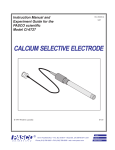
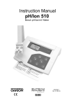
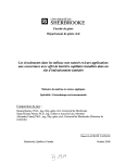
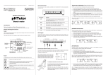
Instruction Manual and Experiment Guide for the PASCO scientific Model CI-6734 012-06615A 9/97 SODIUM ION SELECTIVE ELECTRODE © 1997 PASCO scientific $7.50 ® better 10101 Foothills Blvd. • P.O. Box 619011 • Roseville, CA 95678-9011 USA Phone (916) 786-3800 • FAX (916) 786-8905 • web: www.pasco.com ways to teach science Sodium Ion Selective Electrode 012–06615A Always use eye protection and gloves when working with chemicals. 012–06615A Sodium Ion Selective Electrode Table of Contents Introduction......................................................................................................................................... 1 Theory .................................................................................................................................................. 1 Equipment ........................................................................................................................................... 2 Included ........................................................................................................................................ 2 Additional Required ...................................................................................................................... 2 Required Solutions .............................................................................................................................. 2 General Preparation ........................................................................................................................... 4 Electrode Preparation.................................................................................................................... 4 Electrode Slope Check Using Science Workshop .......................................................................... 4 Measurement ....................................................................................................................................... 5 Measuring Hints ............................................................................................................................ 5 Sample Requirements ................................................................................................................... 5 Units of Measurement ................................................................................................................... 5 Measurement Procedure .................................................................................................................... 6 Direct Measurement of Sodium .................................................................................................... 6 Low Level Sodium Determination ............................................................................................... 7 Electrode Characteristics ................................................................................................................... 8 Reproducibility ............................................................................................................................. 8 Interferences.................................................................................................................................. 8 Temperature Influences................................................................................................................. 9 Electrode Response ..................................................................................................................... 10 Limits of Detection ..................................................................................................................... 10 pH Effects ................................................................................................................................... 10 Electrode Life ............................................................................................................................. 11 Maintenance .......................................................................................................................................11 Electrode Storage ........................................................................................................................ 11 Specifications ..................................................................................................................................... 12 Troubleshooting Guide ..................................................................................................................... 12 Glassware/Plastic-ware ............................................................................................................... 12 Electrode ..................................................................................................................................... 12 Standards & Reagents ................................................................................................................. 13 Sample ........................................................................................................................................ 13 Technique .................................................................................................................................... 13 Troubleshooting Hints ...................................................................................................................... 13 Technical Support ............................................................................................................................. 17 i Copyright, Warranty, and Equipment Return PleaseFeel free to duplicate this manual subject to the copyright restrictions below. Copyright Notice The PASCO scientific 012-06615 A manual is copyrighted and all rights reserved. However, permission is granted to non-profit educational institutions for reproduction of any part of the Sodium Ion Selective Electrode manual providing the reproductions are used only for their laboratories and are not sold for profit. Reproduction under any other circumstances, without the written consent of PASCO scientific, is prohibited. Limited Warranty PASCO scientific warrants the product to be free from defects in materials and workmanship for a period of one year from the date of shipment to the customer. PASCO will repair or replace at its option any part of the product which is deemed to be defective in material or workmanship. The warranty does not cover damage to the product caused by abuse or improper use. Determination of whether a product failure is the result of a manufacturing defect or improper use by the customer shall be made solely by PASCO scientific. Responsibility for the return of equipment for warranty repair belongs to the customer. Equipment must be properly packed to prevent damage and shipped postage or freight prepaid. (Damage caused by improper packing of the equipment for return shipment will not be covered by the warranty.) Shipping costs for returning the equipment after repair will be paid by PASCO scientific. Credits Author: Peter Boyle Editor: Steve Miller ii Equipment Return Should the product have to be returned to PASCO scientific for any reason, notify PASCO scientific by letter, phone, or fax BEFORE returning the product. Upon notification, the return authorization and shipping instructions will be promptly issued. NOTE: NO EQUIPMENT WILL BE ACCEPTED FOR RETURN WITHOUT AN AUTHORIZATION FROM PASCO. ä When returning equipment for repair, the units must be packed properly. Carriers will not accept responsibility for damage caused by improper packing. To be certain the unit will not be damaged in shipment, observe the following rules: ➀ The packing carton must be strong enough for the item shipped. ➁ Make certain there are at least two inches of packing material between any point on the apparatus and the inside walls of the carton. ➂ Make certain that the packing material cannot shift in the box or become compressed, allowing the instrument come in contact with the packing carton. Address: Phone: FAX: email: web: PASCO scientific 10101 Foothills Blvd. P.O. Box 619011 Roseville, CA 95678-9011 (916) 786-3800 (916) 786-3292 [email protected] www.pasco.com 012–06615A Sodium Ion Selective Electrode Introduction The PASCO scientific Sodium Ion Selective Electrode is used to quickly, simply, accurately, and economically measure sodium ions in aqueous solutions. Theory The Sodium Ion Selective Electrode is composed of a sodium-selective glass membrane bonded to a glass body. When the membrane is in contact with a solution containing sodium ions, an electrode potential develops across the membrane. This electrode potential is measured against a constant reference potential, using an ISE Amplifier and a ScienceWorkshop computer interface. The level of sodium ions, corresponding to the measured potential, is described by the Nernst equation. E = E0 + S log X where: E = measured electrode potential E0 = reference potential (a constant) S = electrode slope ( ≈ 59 mV ) decade X = level of sodium ions in solution The activity, X, represents the effective concentration of free sodium ions in the solution. The activity is related to the free ion concentration, Cƒ, by the activity coefficient, γ by: X = γCƒ Activity coefficients may vary, depending on the total ionic strength, I, determined as: I = 1 ΣCXZX 2 2 where: CX = concentration of ion X ZX = charge of ion X Σ = sum of all of the types of ions in the solution In the case of high and constant ionic strength relative to the sensed ion concentration, the activity coefficient, γ is constant and the activity, X, is directly proportional to the concentration. 1 Sodium Ion Selective Electrode 012–06615A To adjust the background ionic strength to a high and constant value, ionic strength adjuster is added to samples and standards. The recommended ISA for sodium is an ammonium chloride/ammonium hydroxide buffer. Solutions other than this may be used as ionic strength adjusters as long as ions that they contain do not interfere with the electrode’s response to sodium ions. Equipment Additional Required: Included: • Sodium Ion Selective Electrode • Sodium Ion Selective Electrode fill solution • pipette for fill solution Required Equipment • PASCO CI-6738 ISE (Ion Selective Electrode) Amplifier • Science Workshop 2.2.5 or higher • PASCO Science Workshop Computer Interface • Semilogarithmic 4-cycle graph paper for preparing calibration curves. • magnetic stir plate • Lab-ware made of plastic, not glass, for all low level measurements. to ISE Amplifier Sodium Ion Selective Electrode Required Solutions The stock solutions described in this section may be created as described in the text or ordered directly from PASCO. The solutions available for order, and their respective prices are listed on the ‘ISE Working Solution Price List’. • Deionized or distilled water for solution and standard preparation. • Ionic Strength Adjuster (ISA), 4 M NH4Cl/4 M NH4 OH RO E O10 13 SAMPL Re feren ce Fill Solutio n 4MKCI filling pipette Figure 1. Included Equipment filling solution To prepare this solution, half fill a 1000 ml volumetric flask with distilled water and add 214 grams of reagent-grade ammonium chloride (NH4Cl). Under a hood, add 270 ml of concentrated ammonium hydroxide (NH4OH), swirl the flask gently to dissolve the solid, and allow to cool. Fill the flask to the mark with distilled water, cap, and upend several times to mix the solution. • Sodium Electrode Storage Solution, 5 M NaCl To prepare this solution, add 29.2 grams of reagent-grade sodium chloride (NaCl) to 100 ml of distilled water. To each 100 ml storage solution, add 2 ml of ISA. 2 012–06615A Sodium Ion Selective Electrode ä Note: Electrodes must not be stored in distilled water or air. Do not rinse with distilled water. • Dilute Electrode Rinse Solution To prepare this solution from your own laboratory stock, add 20 ml of ISA to a one liter volumetric flask and fill to the mark with distilled water. Use this solution to rinse the electrode between measurements. • Sodium Standard, 0.1 M NaCl To prepare this solution, half fill a one liter volumetric flask with distilled water and add 5.84 grams of reagent-grade NaCl. Swirl the flask gently to dissolve the solid. Fill the flask to the mark with distilled water, cap, and upend several times to mix the solution. • Sodium Standard, 1,000 ppm Na+ To prepare this solution, half fill a one liter volumetric flask with distilled water and add 2.542 grams of reagent grade NaCl. Swirl the flask gently to dissolve the solid. Fill the flask to the mark with distilled water, cap, and upend several times to mix the solution. • Sodium Standard, 100 ppm Na+ To prepare this solution, half fill a one liter volumetric flask with distilled water and add 0.254 grams of reagent grade NaCl. Swirl the flask to dissolve the solid. Fill the flask to the mark with distilled water, cap, and upend several times to mix the solution. 3 Sodium Ion Selective Electrode 012–06615A General Preparation fill hole Electrode Preparation 1. Remove the rubber cap covering the electrode tip and the rubber insert covering the filling hole of the Sodium Ion Selective Electrode. Fill the electrode with the included filling solution to a level just below the fill hole. No preparation is required with a sealed reference electrode. 2. Connect the Sodium Ion Selective Electrode to the ISE Amplifier and insert the DIN connector of the ISE Amplifier into analog channel A or B on a PASCO Computer Interface (Figures 2b and 2c). rubber sleeve a rubber cap b Insert DIN connector into analog channel A or B . Electrode Slope Check Using ScienceWorkshop (check electrodes each day) 1. To a 150 ml glass beaker, add 100 ml of distilled water and 2 ml of ISA. Place the beaker on a magnetic stirrer and begin stirring at a constant rate. Start the ScienceWorkshop software, select the Ion Selective Electrode sensor, open a Digital display, change the number of digits to the right of the decimal from 1 to 3, and begin monitoring data. Lower the electrode tip into the solution. 2. Using a pipette, add 1 ml of 0.1 M or 1,000 ppm sodium standard to the beaker. When the reading has stabilized, record the voltage reading indicated in the Digits display. 3. Using a pipette, add 10 ml of the same sodium standard used above to the beaker. When the reading has stabilized, record the voltage reading indicated in the Digits display. c Rotate ring one-quarter turn to secure ISE Amplifier electrode connector Figure 2 Equipment Setup. a: filling the electrode with filling solution; b & c: connecting the electrode to the ISE Amplifier and to the computer interface 4. Determine the difference between the two readings. A difference of 59 ± 4mV indicates correct electrode operation assuming the solution temperature is between 20 °C and 25 °C. See the Troubleshooting sections if the potential change is not within this range. ➤ Note: Slope is defined as the change in potential observed when the concentration changes by a factor of 10. 4 012–06615A Sodium Ion Selective Electrode Measurement Measuring Hints • All samples and standards should be at the same temperature for precise measurement, preferably ambient temperature. A difference of l °C in temperature will result in about a 2% measurement error. The electrodes should not be used above 70 °C. • Constant, but not violent, stirring is necessary for accurate measurement. Magnetic stirrers can generate sufficient heat to change the solution temperature. To counteract this effect, place a piece of insulating material, such as a styrofoam sheet, between the stirrer and the beaker. • Always rinse the electrodes with electrode rinse solution from a wash bottle between measurements. Use a clean, dry tissue to prevent cross contamination. Never use distilled water. • Store the electrodes in electrode storage solution between measurements. Do not store in air or distilled water. Always soak new electrodes overnight in electrode storage solution prior to first use. When making low level sodium measurements, use a dilute sodium chloride storage solution. Add 1 ml of ISA to 100 ml of dilute storage solution. • Plastic lab-ware should be used for low level measurements (< 1 ppm). • All measurements should be made in basic solution. All samples and standards should be adjusted to a pH > 9 with ISA. • For samples with high ionic strength, prepare standards whose composition is similar to the sample. • Always check to see that the membrane is free from air bubbles after immersion into standard or sample. Sample Requirements • The sample measuring range is pH 9–12. Use the ISA recommended to adjust the pH for best accuracy. Make sure that the samples and standards are at the same temperature. The glass electrode sensing bulb will not be attacked by most organic solvents. Units of Measurement Sodium concentrations are measured in units of parts per million, equivalents per liter, soles per liter, or any other convenient concentration unit. Table 1 indicates some of the concentration unit conversion factors. TABLE 1 Concentration Unit Conversion Factors ppm Na+ moles/liter Na+ 229.90 22.99 2.30 1.0 X 10⁻² 1.0 X 10⁻³ 1.0 X 10⁻⁴ 5 Sodium Ion Selective Electrode 012–06615A Measurement Procedure Direct Measurement Direct measurement is a simple procedure for measuring a large number of samples. A single meter reading is all that is required for each sample. The ionic strength of samples and standards should be made the same by adjustment with ISA for all sodium solutions. The temperature of both sample solution and of standard solutions should be the same. Direct Measurement of Sodium ä Note: A calibration curve is constructed on semilogarithmic paper. The measured electrode potential (linear axis) is plotted against the standard concentration (log axis). In the linear region of the curve, only two standards are necessary to determine a calibration curve. Calibration solutions close to the anticipated value of the “unknown” should be chosen. In the nonlinear region, additional points must be measured. The direct measurement procedures given are for the linear portion of the curve. The nonlinear portion of the curve requires the use of low level procedures. 1. By serial dilution of the 0.1 M or 1,000 ppm standards, prepare 100 ml of l0-2 M, l0-3 M, and l0-4 M or 100 and 10 ppm sodium standards. Add 2 ml of ISA per 100 ml of standard. Prepare standards with a composition similar to the samples if the samples have an ionic strength above 0.l M 2. Place the most dilute solution (l0-4 M or 10 ppm) in a beaker Place the beaker on the magnetic stirrer and begin stirring at a constant rate. After assuring that ScienceWorkshop is operating, lower the electrode tip into the solution. When the reading has stabilized, record the voltage reading indicated in the Digits display. 3. Place the mid-range solution (l0-3 M or 100 ppm) in a beaker. Place the beaker on the magnetic stirrer and begin stirring. After rinsing the electrodes with electrode rinse solution, blot dry and immerse the electrode tip in the solution. When the reading has stabilized, record the voltage reading indicated in the Digits display. 4. Place the most concentrated solution (l0-2 M or 1,000 ppm) in a beaker. Place the beaker on the magnetic stirrer and begin stirring. After rinsing the electrodes with electrode rinse solution, blot dry and immerse the electrode tip in the solution. When the reading has stabilized, record the voltage reading indicated in the Digits display. 5. Using the semilogarithmic graph paper, plot the voltage reading (linear axis) against the concentration (log axis). Extrapolate the curve down to about 5.0Xl0-5 M. For measurements below this level, follow the instructions for low-level measurement. A typical calibration curve can be found in Figure 3. 6 012–06615A Sodium Ion Selective Electrode +140 +100 10-fold change +60 ~59 mV electrode potential (mV) +20 -20 -60 0.1 10 -6 1 10 -5 10 (ppm) 10 - 4 100 10 -3 1,000 10 -2 10 -1 + Na concentration (M) Figure 3 Typical sodium electrode calibration curve 6. To a clean, dry 150 ml beaker, add 100 ml of sample and 2 ml of ISA. Place the beaker on the magnetic stirrer and begin stirring. After rinsing the electrode tip with electrode rinse solution, blot dry and place the electrode tip in the solution. When the reading has stabilized, record the Voltage reading in the Digits Display. Using the calibration curve, determine the sample concentration. 7. The calibration should be checked every two hours. Assuming no change in ambient temperature, place the electrode tip in the mid-range standard. After the reading has stabilized, compare it to the original reading recorded in step 3 above. A reading difference by more than 0.5 mV or a change in the ambient temperature will necessitate the repetition of steps 2-5 above. A new calibration curve should be prepared daily. Low Level Sodium Determination This procedure is recommended for solutions with ionic strength less than 1.0x10⁻² M and a sodium concentration less than lxl0-5 M or 1 ppm. If the solution is high in ionic strength, but low in sodium, use the same procedure, but prepare a calibration solution with a composition similar to the sample. Use plastic lab-ware for low sodium measurements. 1. Using 20 ml of standard ISA, dilute to 100 ml with distilled water. 2. Dilute 20 ml of the outer chamber filling solution to 100 ml with distilled water and fill the reference electrode if using a double junction reference electrode. 3. Dilute 1 ml of the 0.l M standard to 100 ml to prepare a 1.0Xl0-3 M standard solution for measurements in moles per liter. Dilute 10 ml of the 1000 ppm standard solution to 100 ml to prepare a 100 ppm standard solution for measurements in ppm. Add 1 ml of low level ISA to each 100 ml of standard. Standards should be prepared fresh daily. 4. Using a 150 ml plastic beaker, add 100 ml of distilled water and 1 ml of low level ISA. Add NH4OH, if necessary, to adjust the pH above 9. Place the beaker on the magnetic stirrer and begin stirring at a constant rate. 5. Place the electrode tip in the solution. Assure that ScienceWorkshop is operating. 7 Sodium Ion Selective Electrode 012–06615A 6. Add increments of the l.0xl0-3 M or 100 ppm standard as given in Table 2 below. 7. After the reading has stabilized, record the Voltage reading in the Digits display after each addition. TABLE 2: Step-wise Calibration for Low Level Sodium Measurements Step Pipette 1 2 3 4 5 6 7 A A A A A B B Added Volume (ml) 0.1 0.1 0.2 0.2 0.4 2.0 2.0 Concentration ppm M 0.10 0.20 0.40 0.60 0.99 2.91 4.76 l.0 X l0-6 2.0 X l0-6 4.0 X l0-6 6.0 X l0-6 9.9 X 10⁻⁶ 2.9 X l0-5 4.8 X l0-5 Pipette A = 1 ml graduated pipette Pipette B = 2 ml pipette Solutions: additions of 100 ppm or 1.0 X l0-3 M standard to 100 ml of solution prepared in step 3 above 8. On semilogarithmic graph paper, plot the millivolt reading (linear axis) against the concentration (log axis) as in Figure 3. 9. Rinse the electrodes with electrode rinse solution and blot dry. 10. To a 150 ml plastic beaker add 100 ml of sample and 1 ml of low level ISA. Place the beaker on the magnetic stirrer and begin stirring. Adjust the pH, if necessary, to above 9. Lower the electrode tip into the solution. After the reading has stabilized, record the Voltage reading in the Digits Display and determine the concentration from the low level calibration curve. 11. Prepare a new low level calibration curve daily. Check the calibration curve every two hours by repeating steps 3-8. Electrode Characteristics Reproducibility Electrode measurements reproducible to +2% can be obtained if the electrode is calibrated every hour. Factors such as temperature fluctuations, drift, and noise limit reproducibility. Reproducibility is independent of concentration within the electrode’s operating range. Interferences Table 3 lists some common cations that, if present in high enough levels, will cause electrode interferences and measurement errors or electrode drift when using the sodium ion electrodes. Most samples do not contain or contain very little of the cations shown in Table 3. The ammonium ion (NH4+), found in the recommended ISA, will not result in an error if all samples and standards have the same level of ISA present. 8 012–06615A Sodium Ion Selective Electrode Electrode drift and slow response could indicate the presence of high interference from the ions listed. Soak the electrodes in electrode storage solution when this happens to restore proper response. See Measuring Hints section. TABLE 3: Levels of Interfering Ions Resulting in a 10% Error at Specified Levels of Sodium Interference -4 1.0X10 M +1 5X10 M +1 1X10 M Li K +1 Rb NH4 +1 -3 1.0X10 M -4 5X10 M -2 -2 1.0X10 M -3 5X10 M 1X10 M -1 1M -1 3M -1 3M -9 -8 3X10 M 3X10 M -2 +1 3X10 M 3X10 M 3X10 M Tl+1 5X10⁻² M 5X10⁻¹ M Interference 1 ppm 10 ppm 100 ppm +1 1.5 ppm 15 ppm 150 ppm +1 17 ppm 170 ppm 1,700 ppm Ag Li K +1 Rb NH4 Ag Tl +1 +1 +1 4 1.1X10 ppm 3 -7 5 4 1.1X10 ppm 1.8X10 ppm 1.8X10 ppm 0.0001 ppm 0.001 ppm 0.01 ppm 3 4.5X10 ppm 4 4.5X10 ppm Temperature Influences Samples and standards should be at the same temperature, since electrode potentials are influenced by changes in temperature. A l °C difference in temperature results in a 2% error at the l0-3 M level. Because of solubility equilibria on which the electrode depends, the absolute potential of the reference electrode changes slowly with temperature. The slope of the electrode, as indicated by the factor “S” in the Nernst equation, also varies with temperature. Table 4 indicates the variation of theoretical slope with temperature. Provided that temperature equilibria has occurred, the sodium ion electrodes can be used at temperatures from -5 ° to 70 °C. Room temperature measurements are recommended, since measurements at temperatures markedly different from room temperature may require equilibrium times up to one hour. The electrode should not be used at temperatures above 70 °C, since damage to the membrane may result. TABLE 4: Temperature vs. Values for the Electrode Slope Temperature ( ºC) 0 10 20 25 30 40 50 “S” 54.20 56.18 58.16 59.16 60.15 62.13 64.11 9 Sodium Ion Selective Electrode 012–06615A Electrode Response Plotting the electrode potential against the sodium concentration on semilogarithmic paper results in a straight line with a slope of about 59 mV per decade. (Refer to Figure 1.) The time needed to reach 99% of the stable electrode potential reading, the electrode response time, varies from one minute or less for sodium concentrations above 1.0X10⁻⁵ M to several minutes near the detection limit. (Refer to Figure 4.) +125 10-3 M to 10-2 M NaCl +100 +75 +50 electrode potential (mV) +25 10-3 M to 10-4 M NaCl 0 10-3 M to 10-5 M NaCl -25 -50 10-3 M to 10-6 M NaCl -75 1 2 3 4 time (minutes) Figure 4 Typical sodium electrode time response to step changes in NaCl Limits of Detection The upper limit of detection in pure sodium solutions is 1 M. In the presence of other ions, the upper limit of detection is above l0-1 M sodium, but two factors influence this upper limit. Both the possibility of a liquid junction potential developing at the reference electrode and the salt extraction effect influence this upper limit. Some salts may extract into the electrode membrane at high salt concentrations, causing deviation from the theoretical response. Either dilute samples between l M and l0-1 M or calibrate the electrode at 4 or 5 intermediate points. Free sodium ion concentration down to l.0Xl0-6 M or 0.1 ppm can be measured in basic solutions. For measurements below l0-5 M or 1 ppm, use plastic lab-ware (and low level procedures) since a significant pickup of sodium may occur from glassware due to removal from container walls. pH Effects The electrode response to sodium ions is greatly influenced by the pH of the solution. Hydrogen ion interferes with measurements of low level sodium ion measurements, although the electrode can be used over a wide pH range. (See Figure 5.) 10 012–06615A Sodium Ion Selective Electrode 10-1 M Na+ +180 +160 +140 electrode potential (mV) 10-2 M Na+ +120 +100 +80 10-3 M Na+ +60 +40 H+ Ion Interference +20 10-4 M Na+ 0 2 4 6 8 10 12 14 pH Figure 5 Electrode potential behavior vs. solution pH in pure NaCl solution at 25 ° The edge of the shaded area (the straight line) shown in Figure 5 indicates a minimum pH at which dilute sodium measurements can be made with less than 10% hydrogen ion interference. The pH should be adjusted to a pH greater than 9 by the addition of ISA to all standards and samples for optimal results over the entire concentration range of sodium. Additional ammonium hydroxide may be necessary to adjust the pH to the desired level in some cases. Electrode Life The sodium electrode will last six months in normal laboratory use. On-line measurements might shorten operational lifetime to several months. In time, the response time will increase end the calibration slope will decrease to the point calibration is difficult and electrode replacement is required. Maintenance Electrode Storage The Sodium Ion Selective Electrode should be stored in the sodium electrode storage solution, never in air or in distilled water. A more dilute sodium chloride solution (with pH adjusted through the use of ISA) may be used for storage before low level measurements. For longer storage (longer than two weeks), rinse and dry the sensing glass and cover the glass tip with any protective cap shipped with the electrode. The reference portion of the combination electrode (or the outer chamber of the reference electrode) should be drained of filling solution, if refillable, and the rubber insert placed over the filling hole. 11 Sodium Ion Selective Electrode 012–06615A Specifications Concentration Range: pH Range: Saturated to 1.0Xl0-6 M (0.02 ppm) 5 to 12 (depending on pH level) Temperature Range: -5 °C – 70 °C Resistance: < 200 mohm Reproducibility: ±2% Storage: store in 5 M NaCl with added ISA Size: length = 110 mm diameter = 12 mm cable length = 1 m Troubleshooting Guide The goal of troubleshooting is the isolation of a problem through checking each of the system components in turn: the meter, the glassware, the electrodes, the standards and reagents, the sample, and the technique. Glassware/Plastic-ware Clean glassware is essential for good measurement. Be sure to wash the glassware/plastic-ware well with a mild detergent and rinse very well with distilled or deionized water. Clean glassware will drain without leaving water droplets behind. Electrode The electrodes may be checked by using the procedure found in the sections entitled Electrode Slope Check. 1. Be sure to use distilled or deionized water when following the procedures given in Electrode Slope Check. 2. If the electrode fails to respond as expected, see the sections Measuring Hints and Electrode Response. Repeat the slope check. 3. If the electrode still fails to respond as expected, substitute another Sodium Ion Selective Electrode (if available) that is known to be in good working order for the questionable electrode. 4. If the problem persists, the reagent may be of poor quality, interferences in the sample may be present, or the technique may be faulty. (See Standards & Reagents, Sample, and Technique sections below.) 5. If another electrode is not available for test purposes, or if the electrode in use is suspect, review the instruction manual and be sure to: - Clean and rinse the electrode thoroughly. - Prepare the electrode(s) properly. - Use the proper filling solution. - Adjust the pH and the ionic strength of the solution by the use of the proper ISA. - Measure correctly and accurately. - Review Troubleshooting Hints. 12 012–06615A Sodium Ion Selective Electrode Standards & Reagents Whenever problems arise with the measuring procedure that has been used successfully in the past, be Sure to check the standard and reagent solutions. If in doubt about the credibility of any of the solutions, prepare them again. Errors may result from contamination of the ISA, incorrect dilution of standards, poor quality distilled/deionized water, or a simple mathematical miscalculation. Sample Look for possible interferences, complexing agents, or substances which could affect the response or physically damage the sensing electrode (or the reference electrode) if the electrodes work perfectly in the standard, but not in the sample. Try to determine the composition of the samples prior to testing to eliminate a problem before it starts. (See Measuring Hints, Sample Requirements, and Interferences.) Technique Be sure that the electrode’s limit of detection has not been exceeded. Be sure that the analysis method is clearly understood and is compatible with the sample. Refer to the instruction manual again. Reread General Preparation and Electrode Characteristics. If trouble still persists, call PASCO Technical Support. Troubleshooting Hints Symptom Possible Causes Next Step Out of Range Reading defective electrode check electrode operation electrodes not plugged in properly unplug electrodes and reseat electrodes reference electrode not filled replenish reference filling solution electrodes not in solution put electrodes in solution air bubble on membrane remove bubble by re-dipping electrode 13 Sodium Ion Selective Electrode Symptom Possible Causes Next Step Noisy or Unstable Readings (readings continuously or rapidly changing) electrode exposed to interferences soak overnight in electrode storage solution defective electrode replace electrode ISA not used use recommended ISA stirrer not grounded ground stirrer samples and standards at different temperatures allow solutions to come to room temperature before measurement electrode exposed to interferences soak overnight in electrode storage solution incorrect reference filling solution use recommended filling solution pH too acidic adjust pH with ISA ISA not used use recommended ISA standards contaminated or incorrectly made prepare fresh standards standard used as ISA use ISA electrode exposed to interferences soak overnight in electrode storage solution pH too acidic adjust pH with ISA air bubble on membrane remove bubble by re-dipping probe Drift (reading slowly changing in one direction) Low Slope or No Slope 14 012–06615A 012–06615A Sodium Ion Selective Electrode Symptom Possible Causes Next Step “Incorrect Answer” (but calibration curve is good) incorrect scaling of semilog paper plot voltage potential on the linear axis. On the log axis, be sure concentration numbers within each decade are increasing with increasing concentration. incorrect sign be sure to note sign of millivolt reading correctly incorrect standards prepare fresh standards wrong units used apply correct conversion factor: 1.0X10⁻³ M = 23.0 ppm as Na+1 sample pH too acidic adjust pH with ISA 15 Sodium Ion Selective Electrode 16 012–06615A Technical Support Feedback Contacting Technical Support If you have any comments about the product or manual, please let us know. If you have any suggestions on alternate experiments or find a problem in the manual, please tell us. PASCO appreciates any customer feedback. Your input helps us evaluate and improve our product. To Reach PASCO For technical support, call us at 1-800-772-8700 (toll-free within the U.S.) or (916) 786-3800. fax: (916) 786-3292 e-mail: [email protected] web: www.pasco.com Before you call the PASCO Technical Support staff, it would be helpful to prepare the following information: ➤ If your problem is with the PASCO apparatus, note: - Title and model number (usually listed on the label); - Approximate age of apparatus; - A detailed description of the problem/ sequence of events (in case you can’t call PASCO right away, you won’t lose valuable data); - If possible, have the apparatus within reach when calling to facilitate description of individual parts. ➤ If your problem relates to the instruction manual, note: - Part number and revision (listed by month and year on the front cover); - Have the manual at hand to discuss your questions.