1
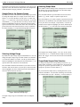
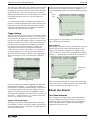
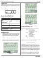
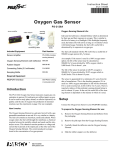
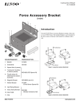
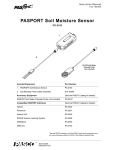
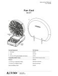
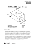
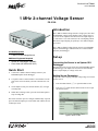
Instruction Sheet
012-10253A
1 MHz 2-channel Voltage Sensor
PS-2190
Introduction
The 1 MHz 2-channel Voltage Sensor is a high speed, two channel PASPORT voltage sensor that has a basic voltage range of
±10 volts. It has amplifiers that allow full-scale input ranges of
±1 volt and ±0.1 volt. The sensor uses an oversampling scheme
that allows input sampling at speeds up to one million samples
per second.
The 1 MHz 2-channel Voltage Sensor connects to a PASPORT
Xplorer GLX datalogger. Measurements are recorded and displayed by the datalogger.
Included Equipment
•
1 MHz 2-channel Voltage Sensor
Additional Equipment Required
•
Xplorer GLX datalogger (PS-2002)
•
Patch Cords (SE-9750 or SE-9751)
2.
Connecting the Sensor to an Xplorer GLX
Datalogger
Plug the sensor into any port on the top of the PASPORT Xplorer
GLX datalogger. The Xplorer GLX screen will automatically
show a Graph display of voltage versus time.
Quick Start
1.
Set-up
Connect the 1 MHz 2-channel Voltage Sensor to your
PASPORT Xplorer GLX datalogger.
Use patch cords to connect Channel 1 and Channel 2 to the
parts of the circuit for which you want to measure the voltage.
3.
On the Xplorer GLX, press the start button (s) to begin
recording data.
4.
When data recording is done, press the start button again to
stop recording data.
Setting Sensor Parameters
Sample rate, data averaging, and input voltage range are set in the
Sensors screen.
•
Press the Home button (h) to open the Home screen.
•
Press F4 (I) under Sensors in the Home screen to open
the Sensors screen.
The sensor measures up to two voltages simultaneously at speeds
up to one million samples per second when used with the GLX in
oscilloscope mode.
Figure 1: Sensor screen
®
1 M H z 2 - c h a n n e l V o lt a g e S e n s o r
The Sensors screen shows the icon and name of the sensor in the
upper left corner, and menus for Sample Rate Unit, Sample Rate,
Reduce/Smooth Averaging, Channel 1, and Channel 2.
Sample Rate in the Sensors Screen
By default, the sensor collects data at 10,000 samples per second.
To change the Sample Rate, for example, use the down cursor
button (d) to select the menu. Use the ‘plus’ or ‘minus’ buttons (-+) to increase or decrease the sample rate, or press the
check button (c) to open the menu. Use the up or down cursor
buttons to highlight the sample rate and press the check button
again to select the choice and exit the menu. The maximum sample rate that can be selected in the Sensors screen is 20,000 Hz
For faster sampling, see “Scope Mode Sample Rate Selection”..
PS-2190
Selecting Scope Mode
The 1 MHz 2-channel Voltage Sensor is designed to be used with
the Xplorer GLX in Scope Mode where the maximum sample
rate of 1,000,000 Hz can be selected.
Press the Home button to open the Home screen. Press the F1
button (F) under ‘Graph’ to open the Graph screen.
Press the F4 button (I) under ‘Graphs’ to open the menu. The
menu choices are numbered. Press the number button of the number of your choice (for example, ‘Scope Mode’), or use the up
and down arrow buttons to highlight your choice and then press
the check button (c) to select the choice and close the menu.
Figure 4: Select Scope Mode
Figure 2: Select sample rate
Selecting Voltage Range
By default, the input voltage range for both channels is ±10 V. To
change the input voltage range for either Channel 1or Channel 2
or to make the channel ‘not visible’, use the up or down cursor
buttons to highlight the menu and press the check button (c) to
open the menu. The menu choices are numbered.
Press the number button for the number of your choice to select
the choice and close the menu, or use the up or down cursor buttons to highlight your choice and then press the check button to
select the choice and close the menu.
The Graph screen changes slightly -- the ‘zero’ on the vertical
axis becomes an ‘x’-- to indicate that the Graph is in the Scope
Mode. The ‘Trigger’ choice in the Tools menu is also automatically selected.
Scope Mode Sample Rate Selection
To change the sample rate in Scope Mode, press the F2 (G)
button under ‘Scale/Move’ in the Graph screen. To increase the
sample rate, press the right cursor button (r). To decrease the
sample rate, press the left cursor button (l).
As you increase the sample rate by rescaling the Time (s) axis
with the ‘Scale/Move’ tool, the units will change from seconds
(s) to milliseconds (ms) and -- ultimately -- microseconds (µs).
Figure 3: Select input voltage range
The input voltage range for each channel can be set independently.
2
Figure 5: Sample rate in Scope Mode
®
1 MHz 2-channel Voltage Sensor
The sample rate is linked to the time resolution on the horizontal
axis. For example, when the horizontal axis scale is 0 to 10 ms,
the sample rate in the Sensor Settings screen is 20,000 Hz. When
the horizontal scale is 0 to 5 ms, the sample rate is 50,000 Hz.
When the horizontal scale is 0 to 2 ms, the sample rate is 100,000
Hz. When the horizontal scale is 0 to 2 µs, the sample rate is
1,000,000 Hz.
PS-2190
Use the up arrow cursor button to increase the Trigger Level. Use
the down arrow cursor button to decrease the Trigger Level. A
horizontal dashed line appears on the graph indicating the Trigger
Level.
‘Rising’
edge
Use of this dynamic sample rate adjustment accomplishes two
purposes: It simplifies adjustment of the Graph to obtain a good
representation of the input and it allows the sensor to perform
averaging of the input signal at lower sample rates and thereby
reduce noise that might be part of the signal.
Trigger Settings
The Trigger choice in the ‘Tools’ menu is automatically selected
when you select Scope Mode. Press the F3 (H) button to open
the Tools menu. The Trigger is a tool that allows you to control
how the GLX collects data. With the Trigger, you make the GLX
delay data recording (after you press s) until a certain condition is met by the incoming data. The Trigger has two parameters: Trigger Edge, which can be ‘Rising’ or ‘Falling’, and
Trigger Level, which specifies the data value that must be
crossed. Press the left arrow cursor button (l) to open the Trigger Settings dialog box (you can also select it from the Tools
menu). By default, the Trigger is ‘Disabled’, the Trigger Edge is
‘Rising’, the Trigger Level is ‘0.00’ and the Stop Condition is
‘Off’.
Figure 7: Trigger Level
Press the right arrow cursor button to cycle through ‘Rising’
edge, ‘Falling’ edge, and ‘Disabled’
Stop Condition
When the Stop Condition is turned on, data collection stops automatically when the GLX reaches the right-hand edge of the
Graph. To turn on the Stop Condition in the Trigger Settings
screen, use the arrow cursor buttons to highlight Stop Condition
and press c. When the Stop Condition is on, an icon and a vertical dashed line appear on the Graph indicating the stop time.
Stop Condition
icon
Figure 6: Trigger Settings
Use the up or down cursor buttons to highlight your choice and
then press the check button (c) to change the selection (e.g.,
from ‘Disabled’ to ‘Enabled’). When the Trigger is ‘Enabled’, an
arrow appears along the vertical axis at the Trigger Level. For
Trigger Level, press the check button to highlight the numeric
value and use the alphanumeric key pad to enter a new value and
then press c again. Press the F1 (F) button to select ‘OK’
or the F2 (G) button to select ‘Cancel’.
Trigger in the Graph Display
The Trigger can be used in normal graph mode to start continuous recording, or it can be used in Scope Mode to repeatedly trigger bursts of data collection. In both modes, the Graph must have
time on the horizontal axis.
®
Figure 8: Stop Condition
While viewing the Graph, hold e and press the left and right
cursor arrow buttons to adjust the stop time. The amount of data
collected is determined by the Graph’s time scale.
About the Sensor
Front Panel Indicators
The front panel has two light-emitting diode (LED) indicators.
The green LED indicates ‘power on’ when the sensor is connected to the Xplorer GLX datalogger. The yellow LED lights
whenever the sensor detects a signal that meets the trigger
requirements set up in the GLX.
3
1 M H z 2 - c h a n n e l V o lt a g e S e n s o r
PS-2190
Trigger In-Out
The PS-2190 has two BNC connectors on the rear panel labeled
Trigger In and Trigger Out. By connecting the Trigger Out of one
PS-2190 to the Trigger In of a second PS-2190, the two sensors
are time synchronized and four channels can be measured. Since
the Xplorer GLX can currently only display two channels in
Scope Mode, this feature is for future use.
RL Circuit
Figure 8: Rear Panel
Basic Specifications
Channels
two, differential
Maximum Sample Rate (Burst
Mode)
1 million samples per second
Maximum Sample Rate
(Continuous Mode)
20,000 sample per second
Input Voltage Ranges
±10 V, ± 1 V, ± 0.1 V full scale
Resolution
12-bit analog-to-digital converter,
5 mV at ±10 volts
Analog Bandwidth
120 kiloHz (-1 dB) typical
Absolute Maximum Input
Voltage Without Damage
45 volts
•
•
Technical Support
For assistance with any PASCO product, contact PASCO at:
Address: PASCO scientific
10101 Foothills Blvd.
Roseville, CA 95747-7100
Suggestions
•
RC Circuit
Measure the voltage of a resistor-inductor-capacitor (RLC)
circuit as an input AC voltage sine waveform ranges from
below resonant frequency to above resonant frequency.
Measure the voltage of a resistor-inductor (RL) circuit with
an input AC voltage square waveform at 50 Hz.
Measure the voltage of a resistor-capacitor (RC) circuit as
the capacitor charges and discharges through the resistor.
Phone:
+1 916-786-3800
(worldwide)
800-772-8700 (U.S.)
Fax:
(916) 786-7565
Web:
www.pasco.com
E-mail:
[email protected]
For more information about the 1 MHz 2-channel Voltage Sensor
and the latest revision of this Instruction Sheet, visit:
www.pasco.com/go?PS-2190
RLC Circuit
4
Limited Warranty For a description of the product warranty, see the
PASCO catalog. Copyright The PASCO scientific 012-10253A 1 MHz
2-channel Voltage Sensor Instruction Sheet is copyrighted with all rights
reserved. Permission is granted to non-profit educational institutions for
reproduction of any part of this manual, providing the reproductions are
used only in their laboratories and classrooms, and are not sold for profit.
Reproduction under any other circumstances, without the written consent
of PASCO scientific, is prohibited. Trademarks PASCO, PASCO scientific, DataStudio, and PASPORT are trademarks or registered trademarks
of PASCO scientific, in the United States and/or in other countries. All
other brands, products, or service names are or may be trademarks or
service marks of, and are used to identify, products or services of, their
respective owners. For more information visit www.pasco.com/legal.
®