1
Operating Instructions
PC Software Package
Model No.
WV-ASC970
Extension Software
Model No.
WV-ASE901
Before attempting to connect or operate this product,
please read these instructions carefully and save this manual for future use.
The model number is abbreviated in some descriptions in this manual.
CONTENTS
Introduction............................................................................ 4
■ Overview.......................................................................... 4
■ Trademarks and Registered Trademarks......................... 4
■ Network Security.............................................................. 4
■ Software License (Licence).............................................. 5
■ Support devices and versions......................................... 5
■ Reference......................................................................... 5
■ What is IP switch node.................................................... 5
Terms and Definitions............................................................. 6
■ Video Switch Node.......................................................... 6
■ Video Link........................................................................ 6
■ Video Path........................................................................ 6
■ Server PC (CPU)............................................................... 6
■ System Unit...................................................................... 6
■ System Domain................................................................ 6
■ System............................................................................. 7
■ Area.................................................................................. 7
Main Features......................................................................... 8
■ Operator Functions.......................................................... 8
● Operator Area Changes................................................ 8
● Operator Log On and Off.............................................. 8
● Operator Class.............................................................. 8
● Operator Priority............................................................ 8
■ Global Video Switch and Video Routing.......................... 8
■ Global Video Camera Control and Operation.................. 9
● Global Camera Seize..................................................... 9
● Camera Control............................................................. 9
● Camera Operation......................................................... 9
■ Global Video Recorder Control and Operation................ 9
● Global Recorder Selection............................................ 9
● Recorder Basic Operation............................................. 9
● Recorder Search Functions......................................... 10
● Recorder Menu Functions........................................... 10
● Recorder Instant Playback Operation......................... 10
■ Global Tour Sequences.................................................. 10
● Local Monitor Seize..................................................... 10
● Tour Sequence Operation........................................... 10
■ Group Preset.................................................................. 11
● Local Monitor Seize and execute................................ 11
■ Group Sequences.......................................................... 11
● Local Monitor Seize..................................................... 11
● Group Sequence Operation........................................ 11
● Group Sequence Priority............................................. 11
■ Global Camera Numbering............................................ 12
● WV-ASC970 Admin Console Setting.......................... 12
● Global Camera Numbering Setting Example.............. 12
● Operation Example...................................................... 12
● Global Tour Sequence Over the domains................... 12
● Return to Current Numbering...................................... 13
■ Alarm Programming and Handling................................. 13
● Program the Alarm...................................................... 13
● Control Alarm.............................................................. 13
● Alarm Action................................................................ 13
■ Alarm Export to other Domains...................................... 14
● Alarm Export Function................................................. 14
● Assign Alarm Export in WV-ASC970 Admin
Console....................................................................... 14
● Setup an Exported Alarm as Global Alarm source in
WV-ASC970 Admin Console....................................... 14
● Reset Exported Alarm Simultaneously........................ 14
2
■ Event Operation............................................................. 14
■ Digital Input and Output Functions................................ 15
■ System-Wide Log View.................................................. 15
■ Time Synchronization..................................................... 15
■ Support WJ-HD616/WJ-HD716 as IP switch node....... 15
■ Support WJ-HD309A/316A as IP switch node.............. 15
■ Support Camera Stream 1 or 2...................................... 15
■ Support Multicast Auto Start......................................... 16
■ Support Internet Mode (Over HTTP).............................. 16
■ Support Third Party I/O-Ethernet Convertor.................. 16
■ Support Audio Control for WV-ASM970........................ 16
■ Alive Monitoring............................................................. 17
■ WJ-ND400 Backup System........................................... 17
■ Priority Rules.................................................................. 17
● Basic Rule................................................................... 17
● Operator Priority.......................................................... 17
● Alarm, Schedule and Operator Priority....................... 17
● Global Operator and Local Operator........................... 17
● Playback and Camera Control ................................... 17
Basic System Configuration Examples................................ 18
■ Standard System with IP switch node .......................... 18
● Network Camera Setup............................................... 19
● Decoder WJ-GXD400 Setup....................................... 19
● Network Disk Recorder WJ-ND400 Setup.................. 19
● Backup Network Disk Recorder WJ-ND400 Setup..... 19
● L3SW #1 Setup........................................................... 19
● L3SW #2 Setup........................................................... 19
● Client Software WV-ASM970 PC setup...................... 19
■ Hybrid System with IP switch node and SX650
switch node.................................................................... 20
● Network Camera Setup............................................... 21
● Decoder WJ-GXD400 Setup....................................... 21
● Network Disk Recorder WJ-ND400 Setup.................. 21
● Network Video Encoder WJ-NT314 Setup.................. 21
● Card Cage WJ-SX650 Setup...................................... 21
● Digital Disk Recorder WJ-HD316A Setup................... 22
● Digital Disk Recorder WJ-HD616/WJ-HD716
Setup........................................................................... 22
● Digital Disk Recorder WJ-RT416 Setup...................... 22
● L3SW Setup................................................................ 22
■ Multiple System Domain with Single IP switch node..... 23
● Network Camera Setup............................................... 24
● Decoder WJ-GXD400 Setup....................................... 24
● Network Disk Recorder WJ-ND400 Setup.................. 24
Basic System Setup Procedure........................................... 25
■ Define a System Domain................................................ 25
● Number of System Domains....................................... 25
● Domain ID and CPU Unit ID Assignments.................. 25
● Enter Unit ID in the WV-ASC970 Admin Console........ 25
● Enter Unit ID in the System Configuration File............ 25
■ Define IP switch node.................................................... 25
● IP switch node............................................................. 25
● IP switch node and its Domain................................... 25
● Enter Cameras/Encoders and Decoders in the
WV-ASC970 Admin Console....................................... 26
● SX650 Switch Node.................................................... 26
● SX650 Switch Node and its Domain........................... 26
● Enter SX650 SUBNODES in the WV-ASC970 Admin
Console....................................................................... 26
■ How to Identify a Video Switch Link.............................. 26
● Links between a WJ-SX650 Switch Node and an
IP switch node............................................................. 26
● Links between two SX650 Switch Nodes................... 27
● Enter Video Links in the
WV-ASC970 Admin Console....................................... 27
■ Define System Operators............................................... 27
● System Operators....................................................... 27
● Enter Global Operators in the WV-ASC970 Admin
Console (Global Database).......................................... 27
● Enter Operator to Unit Partitioning in the
WV-ASC970 Admin Console....................................... 27
■ Other Setup.................................................................... 28
● Alarms......................................................................... 28
● System Controller WV-CU950 Setup.......................... 29
■ Redundant System........................................................ 30
● Connection.................................................................. 30
● Configuration and Operation....................................... 30
■ WJ-ND400 Backup System........................................... 32
● Configuration and operation....................................... 32
● System Configuration File (Alive Monitoring).............. 32
● System Configuration File (WJ-ND400 Backup)......... 32
● For Manual Switchover Operation.............................. 33
● For Automatic Switchover Operation.......................... 33
● For Manual Recover Operation
(Backup WJ-ND400 to Main WJ-ND400).................... 33
● Example Case
(For Automatic Switchover Operation)........................ 34
Operating Procedures with WV-CU950................................ 37
LCD Display Descriptions.................................................... 37
■ Default Status (LCD Display After Login)....................... 37
■ Blinking.......................................................................... 37
■ Messages Displayed on the LCD................................... 37
● Invalid.......................................................................... 37
● Busy............................................................................ 37
● Prohibit........................................................................ 37
Login and Logout................................................................. 38
■ Operation Start (Login)................................................... 38
■ Operation End (Logout).................................................. 38
■ ID Display Function........................................................ 38
Monitor Selection and Camera Selection............................. 39
■ Monitor Selection........................................................... 39
■ Camera Selection........................................................... 39
■ Monitor Lock.................................................................. 39
Display Setting for Controller............................................... 40
■ Adjustment of LCD Display and Buzzer......................... 40
Camera Site Accessories Control........................................ 41
■ Lens Control................................................................... 41
■ Pan/Tilt Control.............................................................. 41
● Manual Operation........................................................ 41
● Auto Panning............................................................... 41
● Program Preset Position............................................. 41
● Call Preset Position..................................................... 42
■ Wiper Control................................................................. 42
■ Defroster Control............................................................ 43
■ Auxiliary Control............................................................. 43
● Operating Procedure................................................... 43
Camera Function Control..................................................... 44
■ Camera Function (Shortcut Function)............................ 44
■ Other Camera Functions................................................ 44
Running Sequence............................................................... 45
■ Tour Sequence............................................................... 45
■ Group Sequence............................................................ 45
■ Call Group Preset........................................................... 46
Monitor Display Control........................................................ 47
■ On-Screen Display Control............................................ 47
■ Alarm History Table........................................................ 47
■ Alarm Status Table......................................................... 48
■ Video Loss Status Table................................................. 48
■ System Status Table...................................................... 48
■ Video Loss History Table................................................ 48
■ Multi-Screen Segment Control...................................... 48
Alarm Control....................................................................... 49
■ Alarm Selection.............................................................. 49
■ Alarm Arming Control..................................................... 49
■ To Operate Alarm-related Camera (ACK)....................... 50
■ To Cancel Alarms........................................................... 50
■ Alarm History Table........................................................ 51
Recorder Control.................................................................. 52
■ Recorder Selection......................................................... 52
● Recorder Auto Selection............................................. 52
● Recorder Manual Selection......................................... 52
■ Time & Date Search Playback........................................ 52
Menu Function Descriptions................................................ 53
■ Menu Functions............................................................. 53
■ To Recall Menu Functions.............................................. 53
Menu Function Details.......................................................... 54
■ Camera Setup................................................................ 54
■ Auto Mode..................................................................... 54
■ BW Mode....................................................................... 54
■ Patrol Learn.................................................................... 55
■ Group Preset.................................................................. 55
■ OSD Control................................................................... 55
■ Digital Output................................................................. 56
■ Alarm Status Table......................................................... 56
■ Video Loss Status Table................................................. 57
■ System Status Table...................................................... 57
■ Video Loss History Table................................................ 58
■ Area Change.................................................................. 59
■ Operator ID.................................................................... 59
■ Controller ID................................................................... 59
■ System Version.............................................................. 59
Appendix 1........................................................................... 60
WJ-SX650 512 x 64 Matrix System Configuration
Example.............................................................................. 60
● Overview...................................................................... 60
● Network Board Installation.......................................... 61
● Connect with WV-ASC970 Server............................... 61
● MODE Switch Settings................................................ 62
● WV-ASC970 Admin Console Setup............................ 62
● Vertical Interval Synchronization................................. 63
● Connect with Each SX650 SubNode via Coaxial
Cables......................................................................... 63
Appendix 2........................................................................... 67
● The "sys.ini" file example............................................ 67
Appendix 3........................................................................... 75
WJ-HD616/WJ-HD716 IP switch node Configuration
Example.............................................................................. 75
● Decoder WJ-GXD400 Setup....................................... 76
● Digital Disk Recorder WJ-HD616/716 Setup.............. 76
● L3SW #1 Setup........................................................... 76
● L3SW #2 Setup........................................................... 76
● Client Software WV-ASM970 PC setup...................... 76
Troubleshooting.................................................................... 77
3
Introduction
■Overview
The WV-ASC970 is distributed video security system software capable of supporting up to 64 security system
domains. The WV-ASC970 system domain can work as a standalone system or together with other domains to
form a large-scale video security system.
The WV-ASC970 can be installed with a specified standard Server PC running specified Linux OS.
For each Server PC based domain, it not only manages Network devices based IP video switch node, but also supports SX650 matrix-based analog video switch node.
WV-ASC970 CD-ROM includes both system software and administration console software (Admin Console). The
Administration Console software is installed on Windows based PC and can creates both local and global database
for Domain Servers.
■Trademarks and Registered Trademarks
• Microsoft, Windows, and Internet Explorer are either registered trademarks or trademarks of Microsoft
Corporation in the United States and/or other countries.
• Other names of companies and products contained in these operating instructions may be trademarks or registered trademarks of their respective owners.
■Network Security
As you will use this product connected to a network, your attention is called to the following security risks.
1. Leakage or theft of information through this product.
2. Use of this product for illegal operations by persons with malicious intent.
3. Interference with or stoppage of this product by persons with malicious intent.
It is your responsibility to take precautions such as those described below to protect yourself against the above
network security risks.
• Use this product in a secured network.
• If this product is connected to a network that includes PCs, make sure that the system is not infected by computer viruses or other malicious entities (using a regularly updated anti-virus program, anti-spyware program,
etc.).
• Protect your network against unauthorized access by restricting users to those who log in with an authorized
user name and password.
• Apply measures such as user authentication to protect your network against leakage or theft of information,
including image data, and authentication information (user names and passwords).
4
■Software License (Licence)
This product includes a software component that is licensed by Info-Zip. For more details, refer to "Readme" file in
the CD-ROM.
■Support devices and versions
Refer to "Readme" file in the CD-ROM.
■Reference
• WV-ASC970 Admin Console User's Guide
• PC Software Package WV-ASM970 Series Help file
• MPEG2 Encoder WJ-GXE900/MPEG2 Decoder WJ-GXD900 Operating Instructions (NTSC model only)
• Digital Disk Recorder WJ-HD300/WJ-HD300A/WJ-HD616/WJ-HD716/WJ-RT416 Series Operating Instructions
• Network Disk Recorder WJ-ND200/WJ-ND300/WJ-ND400/WJ-NV200 Series various Instructions
• Matrix Switcher WJ-SX650 Series Operating Instructions
• Panasonic Network Cameras' Instructions
• Network Interface Unit WJ-NT304/WJ-NT314/WJ-GXE500/WJ-GXE100 series Operating Instructions
• Network Video Decoder WJ-GXD400 series Setup Instruction
• System Controller WV-CU950 Series Operating Instructions
• EBL512 fire alarm system Operating Instructions
■What is IP switch node
IP switch node means a switch node that consists with IP network devices (Panasonic Network Cameras, Network
Disk Recorder, Network interface unit and Network Video Decoder).
5
Terms and Definitions
■Video Switch Node
A video switch node is a device or a group of devices that are capable of performing a video switch from any of its
video inputs to any of its video outputs. In the WV-ASC970 based system, there are two types of video switch
nodes: digital switch node and analog switch node.
IP switch node is a digital switch node which can include network cameras, network disk recorders, network interface units and network video decoders.
Analog video switch node is mainly formed with matrix switch devices, matrix control devices, matrix OSD devices
and matrix digital I/O devices. The system currently supports both SX650 and SX850 switch nodes.
■Video Link
A video link is a connection that can pass video from one video switch node to another. It can only transfer video in
one specified direction.
■Video Path
A video path is a connection between video source and video destination, which consists of one or more video
links.
■Server PC (CPU)
Server PC is a Linux-based server computer with WV-ASC970 system software that manages all the system
resources and system devices within a system domain. It usually refers as a system domain computer. Panasonic
recommend using certain model number described in "Readme" file.
■System Unit
System unit refers to a Server PC.
■System Domain
A system domain is an entity that contains one system unit, up to 64 system controllers, only one digital video
switch node, and only one analog video switch node. The domain is capable of performing system tasks as an
independent entity, or working with other domains to create a distributed network security system. In a WV-ASC970
based system, the system assigns its domain number equal to its unit number.
An analog video switch node is always inside a system domain, while a digital video switch node can be across
more than one domain.
6
■System
A system is a collection of one or more system domains.
■Area
An area is an entity that groups together controllers and monitors.
7
Main Features
Important:
• To control the EBL512, it is necessary to register the license for the Extension Software WV-ASE901 (option)
additionally.
■Operator Functions
●Operator Area Changes
The system can be divided into multiple areas (up to 64), and an operator can change from one area to another if
they have the necessary permission.
●Operator Log On and Off
Each system operator is assigned a user ID and password in the Admin Console. A user ID and password are
required for any operators to log on to the system. System administrators can decide to automatically log operators
off if there is no activity for a pre-defined time period.
Note:
• WV-ASM970 can use alphanumeric characters to logon. This is registered by WV-ASC970 Admin Console.
●Operator Class
The system allows administrators to define operator classes (up to 16) with up to 35 different privileges for both
local and global operators.
●Operator Priority
The system administrator can assign a priority to each operator. When two operators compete for system resources, only the operator with the higher priority gets the resources. Refer to the Priority Rules section for more details.
■Global Video Switch and Video Routing
This function allows operators to switch video from one video source to another, if the permission is granted. For
multiple operators competing for the same resource, it only allows the highest priority operator to perform this function. The next highest priority operator gains control when the highest priority operator releases the resource. Here
is a sample operation to switch video from local camera number 1 in domain 1, to another camera number 1 in
domain 2, on a local monitor number 1.
1. Login to System Controller: Enter 500 for ID and enter 500 for password (Global Operator).
2. Select monitor 1: Enter 1 and press MONITOR key.
3. Select local camera 1: Enter 1 and press CAMERA key.
4. Select global camera 1 (Unit2's camera 1): Enter 200001 and press CAMERA key.
Note:
• Format: Unit (Domain) id (2) + Camera number (1). E.g. 200001 (Unit 2, Camera 1)
(Note that first entry digit must be non-zero, and must not exceed eight digits).
• Only Global Operator can access foreign domain resources.
8
Please note that first entry digit must be non-zero, and must not exceed 2 digits. Also, entry will overflow if the
domain ID entered is greater than 64.
Note:
• For a local camera selection, just enter the logical camera number. (Refer to p. 39.)
■Global Video Camera Control and Operation
●Global Camera Seize
Operators must seize a camera in order to perform camera operations. Following the steps in Global Video Switch
and Video Routing (refer to p. 8), you should be able to seize a camera 200001, which means a camera in domain 2
with a camera ID of 1.
●Camera Control
The system provides operators with camera control functions. The supported functions are: pan, tilt, zoom, focus,
and iris.
●Camera Operation
The system provides operators with the following camera operation functions:
• Camera menu control (analog switch node only)
• Camera preset call and programming
• Camera receiver control
■Global Video Recorder Control and Operation
●Global Recorder Selection
Operators must seize a hard disk recorder and/or network disk recorder in order to perform recorder operations.
After Global Video Switch and Video Routing (refer to page 8), you can seize a recorder 200001, which means a
recorder in domain 2 with a recorder ID of 1.
●Recorder Basic Operation
The system provides operators with the following video recorder functions:
• Recording
• Playback, pause, and stop
• Fast-forward and rewind playback at different speeds (digital disk recorder only)
• Video input channel selection (digital disk recorder only)
• Multiscreen segment switching (digital disk recorder only)
Note:
• For the playback, there are restrictions below.
In the 6-screen, WJ-GXD400 does not support 4VGA (1 280 x 960) or more in the VGA screen.
In the 3-screen, WJ-GXD400 support up to 4VGA (1 280 x 960) in the large screen.
9
●Recorder Search Functions
The system provides operators with the following recorder search functions:
• Date-and-time search playback
• Recording event search (Thumbnail or list search) (digital disk recorder only)
• VMD search (Video motion detection search) (digital disk recorder only)
Note:
• Whether these functions are available or not depends on recorder model.
●Recorder Menu Functions
The system provides operators with the following recorder menu functions:
• Recorder setup menu (digital disk recorder only)
• Disk selection menu (digital disk recorder only)
• A – B repeat playback menu (digital disk recorder only)
• Filter cancellation menu (digital disk recorder only)
Note:
• Whether these functions are available or not depends on recorder model.
●Recorder Instant Playback Operation
The system provides operators with the instant playback operation for a seized global camera.
■Global Tour Sequences
●Local Monitor Seize
The system allows global operators to start and control a tour sequence from another system domain. Before tour
sequence operation, a local monitor must be seized. Here is the sample procedure to seize local monitor number 1
in domain 1:
1. Login to System Controller: Enter 500 for ID and enter 500 for password (Global Operator).
2. Select monitor 1: Enter 1 and press MONITOR key.
●Tour Sequence Operation
Tour sequence operations include start, stop, pause, run, next step, and previous step. Here is the sample to start a
tour sequence:
Run global tour sequence 1(Domain 2's tour sequence 1):
Enter 20010001 and press TOURSEQ key.
Note:
• Format: Unit (Domain) id (2) + Area number (1) +Tour number (1). E.g. 20010001
• Only Global Operator can access foreign domain resources.
Please note that the first entry digit must be non-zero, and must not exceed 2 digits. Also, the entry will overflow if
the domain ID entered is greater than 64.
10
Note:
• To select a local tour sequence, just enter the logical tour sequence number. (Refer to p. 45.)
• The system supports up to 256 tour sequences running.
• During 3 seconds dwell time in case of WJ-GXD400, the video and OSD display will delay according to switching channel numbers.
■Group Preset
●Local Monitor Seize and execute
The system allows operators to execute a group preset in only local domains. Before starting a group preset start, a
local monitor must be seized. Be sure that the group preset monitors are not seized by operators with higher priority.
■Group Sequences
●Local Monitor Seize
The system allows operators to start and control a group sequence in only local domains. Before starting a group
sequence operation, a local monitor must be seized. Be sure that the group sequence monitors are not seized by
operators with higher priority.
●Group Sequence Operation
Group Sequence operations include start, stop, pause, run, next step, and previous step. (Refer to p. 45.)
●Group Sequence Priority
If another operator with higher priority has seized a Group Sequence monitor, that monitor will maintain the original
operator priority.
Note:
• Group Sequence monitors should be the same in each step of sequence and less than 33.
• During 3 seconds dwell time in case of WJ-GXD400, the video and OSD display will delay according to switching channel numbers.
• Group Sequence is not restored after reboot or switchover.
• When an operator select one of running group sequence monitor that is seized by other operator with same priority, the sequence keeps running.
When a operator seized one of running group sequence monitor that is not seized by the other operator with
same priority, the sequence stops.
11
■Global Camera Numbering
This function allows operators to select global camera by just input a logical camera number that is unique number
in the whole multiple domains system. The global camera number can be assigned from 1 to 9999999.
●WV-ASC970 Admin Console Setting
If operators would like to use global camera numbering, the system administrator should turn on the global camera
numbering select check box in the WV-ASC970 Admin Console CPU screen first. Then he/she retrieve all camera
databases from each domain.
And then he/she should assign the global camera number to each domain's camera on the WV-ASC970 Admin
Console screen manually.
Note:
• The assigned global camera numbering database is included in the WV-ASC970 Admin Console global database. It is necessary to download not only local database, but also global one.
• In the multiple domains system, the global camera numbering and the current numbering cannot be mixed up. It
is necessary to download same global database to each domain.
●Global Camera Numbering Setting Example
Global Logical Camera Number
Unit ID
Local Logical Camera Number
2043
3
1
2044
2
2
2045
1
3
2046
3
3
●Operation Example
1. Login to System Controller: Enter 500 for ID and enter 500 for password (Global Operator).
2. Select monitor 1: Enter 1 and press MONITOR key.
3. Select a global camera 2043: Enter 2043 and press CAMERA key.
4. Then the Unit3's camera 1 is displayed on the monitor 1.
Note:
• Only Global Operator can access foreign domain cameras.
In above example, the local operator in the Unit 3 cannot select camera 2044 and 2045.
• When a local operator performs the camera NEXT/PREV operation (or +/- key operation), the foreign domain
cameras are skipped.
• If there is no video link, operator cannot select the foreign domain cameras.
●Global Tour Sequence Over the domains
By using global camera number, the system administrator can configure the Global Tour Sequence over the
domains. Only Global Operator can see all steps on the tour. The local operator can see only local cameras in the
tour.
The global tour sequence over the domains can be assigned from 1 to 9999 and maximum records are 5000.
12
●Return to Current Numbering
If operators would like to return to the current numbering, the system administrator should turn off the global camera numbering select check box in the WV-ASC970 Admin Console CPU screen.
■Alarm Programming and Handling
●Program the Alarm
This function allows administrators to program alarms, assign alarm display targets, and define alarm actions.
●Control Alarm
Alarm controls are operator functions. These functions allow the highest priority operator to seize the alarm and
control it. These functions also allow the next highest priority operator to gain control after the highest priority operator releases the alarm.
The alarm controls include:
• Arm and disarm alarms
• Acknowledge active alarms
• Reset acknowledged or active alarms
The system also supports automatically resetting and acknowledging alarms through configuration by the Admin
Console.
●Alarm Action
The system supports the following alarm actions:
• Camera spots (both local and global)
• Tour sequences (both local and global)
• Group sequence
• Text display (Only WJ-SX650 or WJ-SX850 switch node)
The system supports up to 10 alarm actions, and allows operators to control acknowledged alarm actions.
Note:
• The system can handle up to 64 alarms at the same time. In case of more than 64 alarms, some delay happens
before alarm actions.
• If a higher priority operator seize the alarm target monitor, the alarm action is not executed. In this case, the target monitor connected to WJ-GXD400 shows red frame, while the monitor connected to WJ-SX650 or WX850
blinks OSD texts.
13
■Alarm Export to other Domains
●Alarm Export Function
This function allows a local alarm to export to other system domains.
●Assign Alarm Export in WV-ASC970 Admin Console
In the WV-ASC970 Admin Components screen, select the Alarm Export tab. From there, you can edit an alarm to
be exported to multiple system domains (units). The alarm ID has the following format:
Unit (Domain) id (2) + Alarm id (1). E.g. 20001
In the above format, the domain ID has up to 2 digits and its range is from 1 … 64. The domain ID here is also
called alarm source domain, which means that the alarm originates from that domain.
●Setup an Exported Alarm as Global Alarm source in WV-ASC970 Admin Console
After creating an alarm to be exported to a destination domain, an administrator must enter the alarm information
into the destination domain alarm database using its WV-ASC970 Admin Console.
In the WV-ASC970 Admin Console main menu, select Records from the Alarm command on the Components
menu. For alarm Source, select the source type Global Alarm and ID to 20001 (in the above case).
●Reset Exported Alarm Simultaneously
In case that the Global Alarm Reset Synchronization check box in WV-ASC970 Admin Console is turned on, when
an operator reset the exported alarm in local unit, the exported alarms in other remote units are reset simultaneously.
■Event Operation
The function allows administrators to program system events. The event function currently supports following operations:
• Camera spot
• Tour sequence
• Group Preset
• Group Sequence
• Arm and disarm alarm
• Up to 4 system modes
Note:
• The event function does not support the system modes during switchover in the redundant system.
14
■Digital Input and Output Functions
This function allows operators to select and set digital output ports. The system alarm function can program the
digital output ports as part of the alarm state change indication. The system alarm function can also program the
digital input ports as alarm trigger sources.
■System-Wide Log View
The system supports the following system logs:
• Operator log
• Alarm log
• Video Loss log
• Switch log
In the WV-ASC970 Admin Console main screen select the Tools, Logs, and System links to view system wide user
logs and alarm logs.
Note:
• Each log file is saved based on pre-defined frequency in the "sys.ini" file. Also when the log size reaches
approximately 500 KB, the new file is created.
• The Switch log takes all switching information between monitor and camera.
■Time Synchronization
The System Server can work as a stand-alone time server for IP switch node devices. Refer to WV-ASC970 Admin
Console User's Guide to setup time server.
■Support WJ-HD616/WJ-HD716 as IP switch node
The System Server can handle the WJ-HD616/716 as an IP switch node.
Users can see the analog camera video connected to WJ-HD616/716 on WJ-GXD400 monitor or WV-ASM970
Video Window. Refer to Appendix 3.
■Support WJ-HD309A/316A as IP switch node
The System Server can handle the WJ-HD309A/316A as an IP switch node.
Users can see the analog camera video connected to WJ-HD309A/316A on WV-ASM970 Video Window.
■Support Camera Stream 1 or 2
In order to reduce the commands between the WJ-GXD400 and network cameras, The System Server can specify
the camera stream number 1 or 2, and image capture size of JPEG format for the WJ-GXD400 based on
WV-ASC970 Admin Console settings.
15
■Support Multicast Auto Start
In order to display one network camera video on multiple monitors, the System Server can turn on the multicast
streaming function in the camera. The System Servers send the Multicast Auto Start command to system wide
cameras based on WV-ASC970 Admin Console global settings.
Note:
• When users use this feature, the network administrator should take care of the network band width.
• Also in the WV-ASC970 Admin Console, the CAMERAS menu requires the Access Level 1 (Administrator) User
name and Password for each camera.
■Support Internet Mode (Over HTTP)
The WV-ASM970, Version 6.0 or later, can receive MPEG-4 or H.264 images via the Internet.
The System Servers send the Internet Mode On command to system wide cameras based on WV-ASC970 Admin
Console camera and encoder settings.
Note:
• WJ-GXD400 does not support Internet Mode.
■Support Third Party I/O-Ethernet Convertor
The System Server can support the Third Party I/O-Ethernet Convertor and handle the I/O alarm triggered by the
convertor. The support model numbers are described in the readme file.
■Support Audio Control for WV-ASM970
The WV-ASM970, Version 3.0 or later, supports the Audio ON/OFF control for the WJ-GXD400 through the System
Server. It can turn on or off the audio signal output from an IP switch node device only when users select a monitor
that is assigned to the channel #1 of the WJ-GXD400.
In case that the video format is MPEG4 or H.264, when users turn on the audio control, the WJ-GXD400 shows following icon on channel #1 screen. Although there is no audio stream, this icon will be displayed.
(AUDIO ON)
In case that the video format is JPEG, when users turn on the audio control, the WJ-GXD400 shows following icon
on channel #1 screen. Because it does not support the audio decode in JPEG format.
(AUDIO MUTE)
The WJ-GXD400 does not support audio ON/OFF control during the playback mode. However, users turn on the
audio before playback, the WJ-GXD400 keeps the audio output during the playback.
16
■Alive Monitoring
The System Server checks whether Matrix Switchers, Hard Disk Recorders, IP cameras, Network Disk Recorders
and IP Encoders are alive or not. Users can know the status of these devices in WV-ASM970 Operation Screen and
see the logs of alive monitoring in WV-ASC970 Admin Console's Log Manager screen.
■WJ-ND400 Backup System
When an ASC970 Server detects that Main WJ-ND400 becomes offline or their all hard disk drives become failure,
the ASC970 Server sends the latest configuration data of Main WJ-ND400 to Backup WJ-ND400.
■Fire Alarm System (EBL512) Monitoring
The WV-ASM970, Version 8.0 or later, supports the EBL512 control.
This function is available in specified country. For more detail, please contact to sales company written in the last
page of this document.
■Priority Rules
●Basic Rule
The System Server has the First-Come-First-Serve rule by default when there are same-priority conflicts.
The administrator also can select the Last-Come-First-Serve rule by WV-ASC970 Admin Console.
The First-Come-First-Serve rule is always applied to seizing video links without regard to operator's priority.
●Operator Priority
Operators are controlled by two types of priority. One is Operator priority and other is Controller priority. For priority
conflicts between operators, the Server looks first at Operator priority, then at Controller priority.
●Alarm, Schedule and Operator Priority
Between alarm, schedule and operator, alarm carries the highest priority, next is schedule and last is user.
●Global Operator and Local Operator
Only Global Operator can access other domain devices such as camera, recorder and tour sequence. Global
Operator is applied same priority rule as well as Local Operator except global access.
●Playback and Camera Control
When a user controls a camera, another user who has lower priority can play back the Digital Disk Recorder or
Network Disk Recorder.
When a user plays back the Digital Disk Recorder or Network Disk Recorder, another user who has lower priority
can control the camera even if the user priority is lower.
Note:
• In case of Network Disk Recorder, when a user starts the playback, the System Server makes the user priority
go down the lowest in order for another user to be able to control the camera. And when the user stops the
playback, the server returns the priority to the original. By this manner, if the both user priorities are same, the
user who starts the playback will have camera busy after stop the playback.
17
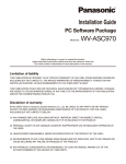
Basic System Configuration Examples
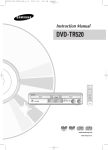
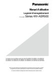
■Standard System with IP switch node
Standard System contains one Server. It can handle up to 1024 network cameras, up to 64 decoders and 64
Network Disk Recorders. The IP addresses in the following diagram are the default addresses of the Server network
ports.
The system also has WV-CU950 controller, WV-ASM970 Client software for global or local operators, and a PC station with WV-ASC970 Admin Console.
The sample database – 01=standard.adm, #=standard.gdm-and sys.ini file – 01A=sys.ini-for WV-ASC970 Admin
Console are provided on the CD-ROM.
Network Cameras
172.16.192.8 to 11
WJ-ND400
Network Cameras
172.16.192.4 to 7
172.16.192.21
Backup WJ-ND400
L3SW #1
172.16.192.22
172.16.192.1
WV-LW2200
Sever PC (WV-ASC970)
172.18.0.1
L3SW #2
PC
with Admin Console
172.18.0.9
WJ-GXD400
WV-CU950
System Controller
(Ethernet)
172.18.0.10
OUT
IN
G
AUDIO OUT VIDEO OUT
PC
with Client software
WV-ASM970
172.18.0.11
18
172.16.192.20
12V
IN
●Network Camera Setup
Refer to each network camera Operational Manual.
Network
IP Address
Subnet Mask Port
Cam
#
1
172.16.192.4 255.255.0.0
80
2
172.16.192.5 255.255.0.0
80
3
172.16.192.6 255.255.0.0
80
4
172.16.192.7 255.255.0.0
80
5
172.16.192.8 255.255.0.0
80
6
172.16.192.9 255.255.0.0
80
7
172.16.192.10 255.255.0.0
80
8
172.16.192.11 255.255.0.0
80
MPEG4
Multicast
Multicast
Address
On
On
On
On
On
On
On
On
On
On
On
On
On
On
On
On
239.192.0.21
239.192.0.22
239.192.0.23
239.192.0.24
239.192.0.25
239.192.0.26
239.192.0.27
239.192.0.28
Multicast
Alarm
Authentication
Port
Destination
ID/Passwd
Address
20000
Server IPA
Default
20000
Server IPA
Default
20000
Server IPA
Default
20000
Server IPA
Default
20000
Server IPA
Default
20000
Server IPA
Default
20000
Server IPA
Default
20000
Server IPA
Default
●Decoder WJ-GXD400 Setup
Refer to WJ-GXD400 Operational Manual.
Dec #
1
IP Address
172.16.192.20
Subnet Mask Port
255.255.0.0
80
Camera Title
Left Lower -2
OSD Position
Time Date
Right Upper +1
Schedule
Additional Info
Left Lower -1
None
Authentication
ID/Passwd
Default
●Network Disk Recorder WJ-ND400 Setup
Refer to WJ-ND400 Operational Manual.
DVR#
IP Address
Subnet Mask
Port
1
172.16.192.21
255.255.0.0
80
Recorder
Ch-Camera link
Necessary
Camera Setup
Schedule
Necessary
Always Recording
Camera Setup
Schedule
Not Necessary
Not Necessary
Authentication
ID/Passwd
Default
Either WJ-ND400's PC port or CAMERA port can be used.
●Backup Network Disk Recorder WJ-ND400 Setup
Refer to WJ-ND400 Operational Manual.
Backup
IP Address
DVR#
1
172.16.192.22
Subnet Mask
Port
255.255.0.0
80
Recorder
Ch-Camera link
Not Necessary
Authentication
ID/Passwd
Default
Either WJ-ND400's PC port or CAMERA port can be used.
Recorder Ch-Camera link, Camera Setup and Schedule data is transferred automatically by WV-ASC970 server
when WJ-ND400 is switched over.
●L3SW #1 Setup
Set a restriction for the multicast packets not to flow to Server PC port.
Valid the IGMP V2 due to support Multicast packets.
●L3SW #2 Setup
Set a restriction for the multicast packets to transfer to the PC with client software WV-ASM970 only.
●Client Software WV-ASM970 PC setup
KBD #
2
IP Address
172.18.0.11
Subnet Mask
255.255.0.0
19
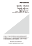
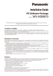
■Hybrid System with IP switch node and SX650 switch node
The following system contains one IP switch node and one SX650 video switch node. The analog video from SX650
can be seen on the GXD400 monitor. The IP switch node consists of network cameras, WJ-GXD400, WJ-NT314
and WJ-ND400. The SX650 video switch node contains a WJ-SX650 cage with Input, Output and Network board
(WJ-PB65E01). There are some video links from WJ-SX650 monitor output to WJ-NT314 coaxial Input. The system
also has WV-CU950 controller for system or local operators, and a PC station with WV-ASC970 Admin Console.
The sample database – 01=hybrid.adm, #=hybrid.gdm-and sys.ini file – 01A=sys.ini-for WV-ASC970 Admin
Console are provided on the CD-ROM.
Note:
• Due to video signal handling between WJ-NT314 and WJ-SX650, WJ-NT314 sometimes sends green picture in
short time when video switching happens frequently. (WJ-NT304 has same behaviors.)
• Be sure to separate the analog switch node network from IP switch node network.
Network Camera
172.16.192.4 to 7
1
WJ-ND400
2
172.16.192.21
L3SW
3
WV-LW2200
4
Network Camera
OUT
IN
4
3
2
1
4
3
VIDEO
2
WJ-NT314
7
OUT
1
AUDIO
WJ-GXD400
SIGNAL
GND
IN
G
OUT
IN
AUDIO OUT VIDEO OUT
172.16.192.20
6
12V
G
172.16.192.8 to 11
5
IN
12V IN
4 3 2 1G 4 3 2 1
OUT
Digital Disk Recorder*1
DATA
IN
ALARM/CONTROL 10/100BASE-T RS-485
172.16.192.22
172.18.0.60
WJ-SX650
8
4
3
2
1
C
3
Cam2
EXTENSION 2 IN
EXTENSION 3 IN
2
Cam4
ALARM IN
Mon1
Cam3
Cam1
1
CAMERA IN
B
3
2
Mon2
1
DATA 2
DATA 1
Video Output Board 2
HDR4/TMNL8 HDR3/TMNL7
TMNL6
TMNL5
Video Output Board 1
HDR2/TMNL4 HDR1/TMNL3
DATA 4
DATA 3
TMNL2
4
3
2
1
A
3
DATA
AC IN
DATA
2
WJ-SX850
10/100 BASE-T
ALARM OUT 2
Cam5
ALARM OUT 1
1
SERIAL
Cam6
192.168.200.1
Cam7
Switching HUB
Cam8
Switching HUB
192.168.200.200
172.18.0.1
WV-CU950
PC with Admin Console
System
Controller
(Ethernet)
172.18.0.9
172.18.0.10
20
172.16.192.1
Sever PC (WV-ASC970)
*1 Configuration Example shows WJ-HD316A
●Network Camera Setup
Refer to each network camera Operational Manual.
Network
Cam
#
1
2
3
4
5
6
7
8
IP Address
Subnet Mask
Port
MPEG4
Multicast
Multicast
Address
172.16.192.4
172.16.192.5
172.16.192.6
172.16.192.7
172.16.192.8
172.16.192.9
172.16.192.10
172.16.192.11
255.255.0.0
255.255.0.0
255.255.0.0
255.255.0.0
255.255.0.0
255.255.0.0
255.255.0.0
255.255.0.0
80
80
80
80
80
80
80
80
On
On
On
On
On
On
On
On
On
On
On
On
On
On
On
On
239.192.0.21
239.192.0.22
239.192.0.23
239.192.0.24
239.192.0.25
239.192.0.26
239.192.0.27
239.192.0.28
Multicast
Alarm
Authentication
Port
Destination
ID/Passwd
Address
20000
Server IPA
Default
20000
Server IPA
Default
20000
Server IPA
Default
20000
Server IPA
Default
20000
Server IPA
Default
20000
Server IPA
Default
20000
Server IPA
Default
20000
Server IPA
Default
●Decoder WJ-GXD400 Setup
Refer to WJ-GXD400 Operational Manual.
Dec #
1
IP Address
172.16.192.20
Subnet Mask Port
255.255.0.0
80
Camera Title
Left Lower -2
OSD Position
Time Date
Right Upper +1
Schedule
Additional Info
Left Lower -1
None
Authentication
ID/Passwd
Default
●Network Disk Recorder WJ-ND400 Setup
Refer to WJ-ND400 Operational Manual.
DVR#
IP Address
Subnet Mask
Port
Recorder
Ch-Camera link
Camera Setup
Schedule
Authentication
ID/Passwd
1
172.16.192.21
255.255.0.0
80
Necessary
Necessary
Always Recording
Default
Either WJ-ND400's PC port or CAMERA port can be used.
●Network Video Encoder WJ-NT314 Setup
Refer to WJ-NT314 Operational Manual.
ENC
#
IP Address
Subnet Mask
Port
Authentication
ID/Passwd
1
172.16.192.22
255.255.0.0
80
Default
●Card Cage WJ-SX650 Setup
Refer to WJ-SX650 Operational Manual to set following configuration.
Slot #
Board name
Rotary Switch/Mode
Qty
C
Video Input Board
0
1
Video Output Board with Network Board
Output Board (1)
1
B
A
Note:
• The SX650 switch node supports up to 512 inputs and 64 output. Refer to the Appendix 1 for the 512 x 64 configuration.
21
●Digital Disk Recorder WJ-HD316A Setup
Refer to WJ-HD316A Operational Manual to set following configuration.
DVR#
Line Speed
HTTP PORT
DHCP
IP Address
Gateway
Unit Address
(System)
Unit Address
(Controller)
1
AUTO
0080
OFF
172.18.0.60/16
0.0.0.0
001
001
Note: The WJ-HD316A series should be set the alarm suspend configuration.
●Digital Disk Recorder WJ-HD616/WJ-HD716 Setup
Refer to WJ-HD616/WJ-HD716 Operational Manual to set following configuration.
DVR#
Line Speed
HTTP PORT
DHCP
IP Address
Gateway
Unit Address
(System)
Unit Address
(Controller)
1
AUTO
0080
OFF
172.18.0.60/16
0.0.0.0
001
001
Note: The WJ-HD616 or WJ-HD716 series should be set the alarm suspend configuration.
●Digital Disk Recorder WJ-RT416 Setup
Refer to WJ-RT416 Operational Manual to set following configuration.
DVR#
Line Speed
HTTP
PORT
Server
PORT
DHCP
IP Address
Gateway
Unit Address
(System)
Unit Address
(Controller)
1
AUTO
0080
02000
OFF
172.18.0.60/16
0.0.0.0
001
002
Note: The WJ-RT416 should be set three different passwords as Manager1, Manager2 and Manager3 and these
should be match to the Password1, Password2 and Password3 defined in Admin Console's DIGITAL
RECORDERS menu.
●L3SW Setup
Set a restriction for the multicast packets not to flow to Server PC port.
Valid the IGMP V2 due to support Multicast packets.
22
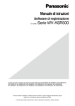
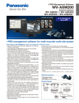
■Multiple System Domain with Single IP switch node
The following system includes two system domains. Each system domain has IP switch node and can work independently as standard system. In order for both domains to work together, WV-ASC970 global Admin database is
necessary in both server PCs.
The sample database – 01=multi_1.adm, 02=multi_2.adm -and sys.ini file – 01A=sys.ini, 02A=sys.ini -for
WV-ASC970 Admin Console are provided on the CD-ROM. The sample database-#=multi.gdm-for global database.
Domain 1
Network Camera 172.16.192.4 to 11
WV-LW2200
1-1
Domain 2
Network Camera 172.16.192.12 to 19
WV-LW2200
2-1
1-2
2-2
1-3
2-3
1-4
2-4
1-5
2-5
Decoder 1-1
1-6
WJ-GXD400
OUT
IN
G
12V
IN
Decoder 2-1
2-6
OUT
IN
G
AUDIO OUT VIDEO OUT
1-7
WJ-GXD400
12V
IN
AUDIO OUT VIDEO OUT
172.16.192.40
1-8
2-7
172.16.192.41
2-8
L3SW
L3SW
172.16.192.1
172.16.192.50
WJ-ND400
172.16.192.2
172.16.192.51
Sever PC (WV-ASC970)
Sever PC (WV-ASC970)
172.18.0.1
172.18.0.1
Switching HUB
PC with Admin Console
172.18.0.9
WJ-ND400
System Controller
(Ethernet)
172.18.0.10
WV-CU950
Switching HUB
PCwith Admin Console
172.18.0.9
System Controller
(Ethernet)
172.18.0.10
WV-CU950
23
●Network Camera Setup
Refer to each network camera Operational Manual.
Network
Cam
#
1-1
1-2
1-3
1-4
1-5
1-6
1-7
1-8
2-1
2-2
2-3
2-4
2-5
2-6
2-7
2-8
IP Address
Subnet Mask
Port
MPEG4
Multicast
Multicast
Address
172.16.192.4
172.16.192.5
172.16.192.6
172.16.192.7
172.16.192.8
172.16.192.9
172.16.192.10
172.16.192.11
172.16.192.12
172.16.192.13
172.16.192.14
172.16.192.15
172.16.192.16
172.16.192.17
172.16.192.18
172.16.192.19
255.255.0.0
255.255.0.0
255.255.0.0
255.255.0.0
255.255.0.0
255.255.0.0
255.255.0.0
255.255.0.0
255.255.0.0
255.255.0.0
255.255.0.0
255.255.0.0
255.255.0.0
255.255.0.0
255.255.0.0
255.255.0.0
80
80
80
80
80
80
80
80
80
80
80
80
80
80
80
80
On
On
On
On
On
On
On
On
On
On
On
On
On
On
On
On
On
On
On
On
On
On
On
On
On
On
On
On
On
On
On
On
239.192.0.21
239.192.0.22
239.192.0.23
239.192.0.24
239.192.0.25
239.192.0.26
239.192.0.27
239.192.0.28
239.192.0.31
239.192.0.32
239.192.0.33
239.192.0.34
239.192.0.35
239.192.0.36
239.192.0.37
239.192.0.38
Multicast
Alarm
Authentication
Port
Destination ID/Passwd
Address
20000
Server IPA
Default
20000
Server IPA
Default
20000
Server IPA
Default
20000
Server IPA
Default
20000
Server IPA
Default
20000
Server IPA
Default
20000
Server IPA
Default
20000
Server IPA
Default
20000
Server IPA
Default
20000
Server IPA
Default
20000
Server IPA
Default
20000
Server IPA
Default
20000
Server IPA
Default
20000
Server IPA
Default
20000
Server IPA
Default
20000
Server IPA
Default
●Decoder WJ-GXD400 Setup
Refer to WJ-GXD400 Operational Manual.
Dec #
IP Address
Subnet Mask Port
OSD Position
Schedule
Authentication
ID/Passwd
Camera Title
Time Date
Additional Info
1
172.16.192.40
255.255.0.0
80
Left Lower -2
Right Upper +1
Left Lower -1
None
Default
2
172.16.192.41
255.255.0.0
80
Left Lower -2
Right Upper +1
Left Lower -1
None
Default
●Network Disk Recorder WJ-ND400 Setup
Refer to WJ-ND400 Operational Manual.
DVR
#
IP Address
Subnet Mask
Port
Recorder
Ch-Camera link
Camera
Setup
Schedule
Authentication
ID/Passwd
1
172.16.192.50
255.255.0.0
80
Necessary
Necessary
Always Recording
Default
2
172.16.192.51
255.255.0.0
80
Necessary
Necessary
Always Recording
Default
Either WJ-ND400's PC port or CAMERA port can be used.
24
Basic System Setup Procedure
■Define a System Domain
●Number of System Domains
By definition, each system domain must have a Server PC. (If it is a redundant system, it must have two Server
PCs). The system can consist of up to 64 system domains.
●Domain ID and CPU Unit ID Assignments
For each Server PC, you must assign a Unit ID.
●Enter Unit ID in the WV-ASC970 Admin Console
In the WV-ASC970 Admin Domain menu, select the CPU Units, and enter the unit information into the fields provided.
●Enter Unit ID in the System Configuration File
In each Server PC, there is a system configuration file named sys.ini. You can view and edit the file through
WV-ASC970 Admin Console. For each new system domain that is set up, you need to enter the correct system Unit
ID in the [UNIT] section of the sys.ini file. The following is the text from the sys.ini file's [UNIT] section.
[UNIT]
***{ The unit ID should be the same as the one defined in }
***{ the Global Admin database for this unit.
}
***{ For single-unit systems, use ID=1. (ID=0 is invalid) }
ID=1
■Define IP switch node
●IP switch node
An IP switch node consists of one or more network camera devices (include video encoder) and video decoder
devices (WJ-GXD400). An IP switch node can be in a single system domain or across multiple system domains.
●IP switch node and its Domain
An IP switch node can include many camera/encoder and decoder devices. In the case of a single domain system,
such as the system on page 18, all the camera/encoder and decoder devices will be assigned to that domain.
The IP switch node can split into multiple system domains. In the case of a multiple domain system, the system
designer has to decide which domain the encoder and decoder devices should belong to.
For the system on page 23, we decided that camera 1-1 to 1-8 and decoder 1-1 are in domain 1, while camera 2-1
to 2-8 and decoder 2-1 are in domain 2.
In general, we recommend that you should search for a nearby Server and assign camera/encoder or decoder
devices to the same Unit ID of the Server.
25
●Enter Cameras/Encoders and Decoders in the WV-ASC970 Admin Console
After deciding the Unit ID for each encoder and decoder, the next step is to enter the encoder and decoder device
information in the WV-ASC970 Admin Console for the domain.
In the WV-ASC970 Admin Console main menu and selecting IP DEVICES screen, we need to configure the devices
here.
Since these devices are part of the IP switch node, select IP from the Switch Nodes command on the Domain
menu.
●SX650 Switch Node
SX650 switch node consists of one more WJ-SX650 matrix switcher with WJ-PB65E01 network board. SX650
switch node can only be located within a system domain, and cannot cross over multiple domains. Currently, the
system only supports up to one SX650 switch node in a single system domain, and node ID is always set to its
domain ID by the system software.
●SX650 Switch Node and its Domain
In case of a single domain system, all the WJ-SX650 matrix switcher with WJ-PB65E01 network board will be
assigned to that domain.
In case of a multiple domain system, the system designer has to decide which domain all the WJ-SX650 matrix
switcher with WJ-PB65E01 network board should belong to.
●Enter SX650 SUBNODES in the WV-ASC970 Admin Console
After deciding the domain ID for each WJ-SX650 matrix switcher, the next step is to enter the information in the
WV-ASC970 Admin Console for the domain.
In the WV-ASC970 Admin Console, SX650 SUBNODES screen, we need to configure the devices. Since these
devices are part of the SX650 node, select SX650 from the Switch Nodes command on the Domain menu.
Following are the sample data for WJ-SX650 matrix switcher.
ID
I/F
IPA
1
1
192.168.200.1
BRIDGE CONTROL
–
1 - 256
OSD
1 - 32
SWITCH
Input
Output
1 - 256
1 - 32
ALARM
–
Address [MODE]
5
6
7
8
EA
OFF OFF OFF ON 00.00.00.00.00.00
■How to Identify a Video Switch Link
●Links between a WJ-SX650 Switch Node and an IP switch node
In order to pass video from one switch node to another, video links are required. Page 20 shows an example of a
system with video links. In general, you can find video links in the following conditions:
• From a matrix switch output to a video encoder device.
The above video links can connect two video switch nodes within the same system domain or different system
domains.
26
●Links between two SX650 Switch Nodes
In general, you can find video links from a matrix switch output to a matrix switch input. These links must cross two
different system domains.
●Enter Video Links in the WV-ASC970 Admin Console
In the ASC970 Admin Console main menu, select the Routing on the Domain menu. The LINK screen will be activated. Then enter the video link(s) here in order for the system to perform video routing properly. The following table
is based on the example from on page 20.
ID
Enable
1
✓
✓
2
Video Source
Video Destination
Navigation
Unit
Switch
Port
Unit
Switch
Dev Id
Ch
Cost
1
SX650
3
1
IP
11
1
1
1
SX650
4
1
IP
11
2
1
In the above video link table, operators are able to enable or disable a video link. The system will not use a link that
is disabled.
Also in the above video link table, the destination Unit ID and source Unit ID are the same. They also can be different in a multiple domain system.
In the example on page 23, there is no video link in the system, and operators can skip this configuration.
■Define System Operators
●System Operators
System operators are also called global operators or system users. In order to seize a system resource, such as a
camera in a foreign domain, the system requires a global operator. When a global operator logs into a system controller, it becomes a global controller.
The global operator is subject to unit partitioning restrictions, where within their domain, she/he will act like a local
super user.
●Enter Global Operators in the WV-ASC970 Admin Console (Global Database)
In the WV-ASC970 Admin Console main screen, select Operators → Records on the Components menu. The
Operators screen will be activated. Then, enter the operator(s) information into the fields provided. For global
operator(s), you can select one of the four global class levels.
User ID
Password
Priority
Timeout
Name
Class
500
500
2
00:00:00
Global Operator 1
20: Global Level 0
100
123
10
00:00:00
Global Operator 2
20: Global Level 0
●Enter Operator to Unit Partitioning in the WV-ASC970 Admin Console
In the WV-ASC970 Admin Console main screen, select Operator → Records on the Components menu. The
Operators screen will be activated. Then, select the Unit tab and check the partitioning you want to apply to a
global operator.
27
■Other Setup
●Alarms
To trigger alarms, setup the alarm source devices and register them to Alarm Source database by using Admin
Console.
# Alarm Type
Alarm Source
1 Camera Motion
analog camera
2
3
4
5
6
7
8
9
10
11
28
How to setup
Turn on MOTION DET setting in dedicated camera
menu.
network camera
1. Select ON for network device's VMD alarm.
2. Set the Server IP Address to network devices'
alarm notification destination IP Address field.
Also set the port number 1818.
I/O Port (Dry conanalog digital input port in
Select SX850 or SX650 node and Register the input
tact) alarm
SX850 or SX650 cage
port setting to Admin I/O Ports menu
network device
1. Select ON for network devices' Terminal alarm.
(network camera,
2. Set the Server IP Address to network devices'
network decoder, DVR)
alarm notification destination IP Address field.
Also set the port number 1818.
RS232C alarm
External system's RS232C
Select RS232 Controller Model for desired port in
I/F
Admin Controllers menu
Video Loss (any)
One of analog cameras via
Turn on Alarm Trigger check box in Admin Cameras
SX850 or SX650 cage
menu.
Video Loss (cam)
A certain analog camera via Turn on Alarm Trigger check box in Admin Cameras
SX850 or SX650 cage
menu.
Global Alarm
Other domains alarms and
Select one or more than one domain that the global
do not care about alarm type alarm should be exported in Admin Alarms menu,
Export tab, UNIT partition menu.
Scene change
WV-NP1000
1. Select ON for NP1000's Scene change detection
detection
WV-NP1004
alarm.
WV-NW484S
2. Set the Server IP Address to NP1000's alarm notification destination IP Address field. Also set the
port number 1818.
Command alarm
network camera
1. Select ON for network devices' Command alarm.
2. Set the Server IP Address to network devices'
alarm notification destination IP Address field.
Also set the port number 1818.
Communication
DVR (except RT416)
1. Set the Port number 1818 for Panasonic alarm.
Error (between cam2. Set the Server IP Address to Panasonic alarm
era and recorder)
destination IP Address field.
Intruder detection
WJ-NT314
See the NT314 Network Operating Instructions.
Object detection
WJ-NT314
See the NT314 Network Operating Instructions.
12 Capacity Warning
DVR (except RT416)
13 RAID Down
DVR (except RT416, ND200)
14 Thermal Error
DVR (except RT416)
15 DVR Error
(any of DVR Error)
DVR (except RT416)
16 Face Matching
WJ-NV200
1. Set the Port number 1818 for Panasonic alarm.
2. Set the Server IP Address to Panasonic alarm
destination IP Address field.
1. Set the Port number 1818 for Panasonic alarm.
2. Set the Server IP Address to Panasonic alarm
destination IP Address field.
1. Set the Port number 1818 for Panasonic alarm.
2. Set the Server IP Address to Panasonic alarm
destination IP Address field.
1. Set the Port number 1818 for Panasonic alarm.
2. Set the Server IP Address to Panasonic alarm
destination IP Address field.
1. Set the Port number 1818 for Panasonic alarm.
2. Set the Server IP Address to Panasonic alarm
destination IP Address field.
3. Activate the face matching alarm action.
Alarm source setup in
Admin Console
Select Motion (cam)
Select I/O Port
Select I/O Port
Select RS232
Select Vid Loss (any)
Select Vid Loss (cam)
Select Global Alarm
Select Scene Change
(cam)
Select Cmd Alm (cam)
Select Comm Err (cam)
Select Intruder (cam)
Select Object dct.
(cam)
Select Capacity Warn
(dvr)
Select RAID Down
(dvr)
Select Therm Err (dvr)
Select DVR Err (dvr)
Select Face Match
(NV200)
Note:
• "analog camera" stands for Panasonic analog cameras.
• "DVR" stands for Panasonic Digital Disk Recorder / Network Disk Recorder.
• In the redundant system, set both Main and Backup WV-ASC970 Servers' IP Addresses to the alarm notification
destination IP Address field of the network device.
• The Capacity Warning, RAID Down and Thermal are also included in DVR Error. For example, if both Capacity
Warning and DVR Error are assigned to different alarms and then the Capacity Warning occurs, both alarms are
triggered.
●System Controller WV-CU950 Setup
To add system controllers to the system in Ethernet communication, add an entry to the system controller database
through the admin console. You need to assign a controller ID for each controller, and enter the Ethernet address
from the bottom of each controller.
Note:
• Refer to the Admin Console User's Guide for details.
The MODE and CONTROLLER No. on WV-CU950 rear panel should be set as shown below.
CONTROLLER No.
MODE
Set as shown below.
Maintain the switch
setting as "1".
OFF
ON
1
2
3
4
5
6
7
8
23
78
901
456
WV-CU
950
MODE
29
■Redundant System
When an ASC970 System includes both a Main CPU and a Backup CPU, it is called a Redundant System. In this
case, one of the WV-ASC970 Server will be running in the Active mode and will actually be controlling the system
operation. The other WV-ASC970 Server will be running in Standby mode and will be following all the system activity in order to take over system operation, in case the Active CPU fails or otherwise can no longer operate.
The WV-ASC970 Admin Console allows an administrator to set and switch the status of the WV-ASC970 Servers on
the CPU Unit screen.
●Connection
WV-ASC970 Server
WV-ASC970 Server
Use same network group
as Admin Console
Switching HUB
Main
9 pin D-sub, female-female cross
cable (Not required for manual
switchover operation)
Note: Secure the connector
screws firmly to prevent cable
disconnection.
WV-ASC970 Server
Backup
1
2
2
3
3
4
4
5
5
6
6
7
7
8
8
Frame
PC with Admin Console
WV-ASC970 Server
1
Shield
Frame
9 pin D-sub, female-female cross cable PINOUT
●Configuration and Operation
WV-ASC970 Admin Console Screen
Auto/Manual radio button
Auto/Manual
Mode setting button
Get CPU Status/Switch
Active CPU button
Redundant check box
Backup IPA
Note:
• This capture screen is an example to show the redundant feature related buttons or fields. Some of details are a
bit different according to the WV-ASC970 Admin Console versions.
30
System Configuration File
If there are more than one serial ports on the WV-ASC970 Server, you need to enter the correct port number in the
[REDUNDANT] section of the sys.ini file.
For Manual Switchover Operation
1. Connect the Ethernet cable between the SYSTEM CONTROLLER ports of both WV-ASC970 Servers.
(SERIAL ports are not used for MANUAL operation.)
2. Turn on the "Redundant" check box on Admin Console's Domain>CPU Units>Unit tab and input the backup
WV-ASC970 Server's IP Address to "Backup IPA" field.
3. Select the "Man (Redundant Manual Switchover)" radio button, and then click the "Mode" button.
4. Put the global database to both WV-ASC970 Servers and reboot both.
Note:
• If the global database is put to only one WV-ASC970 Server, the redundant function does not work properly.
5. By using the Admin Console, click the "Get CPU Status" button on Unit tab.
6. After Admin Console get the current WV-ASC970 status, click the "Switch Active CPU" button. At this point, the
dialog box will be displayed. Select "Switchover", then click "OK" button.
7. The Active WV-ASC970 Server reboots automatically, and moves to Standby state. Another WV-ASC970 Server
moves to Active state.
For Automatic Switchover Operation
1. Connect the 9-pin D-sub cross cable (locally procured) between the SERIAL ports of both WV-ASC970 Servers,
and connect the Ethernet cable between the SYSTEM CONTROLLER ports of the Servers.
2. Turn on the "Redundant" check box on Admin Console's "Domain" > "CPU Units" > "Unit" tab and input the
backup WV-ASC970 Server's IP Address to "Backup IPA" field.
3. Select the "Auto (Redundant Auto Switchover)" radio button and then, click the "Mode" button.
4. Put the global database to both WV-ASC970 Servers and turn off both servers.
Note:
• If the global database is put to only one WV-ASC970 Server, the redundant function does not work properly.
• When activating automatic switchover operation, user should not register a controller to the SERIAL port in the
CONTROLLERS menu of admin console.
5. Turn on Main WV-ASC970 Server first. After it ups, turn on Backup WV-ASC970 Server.
6. When a fatal application software error happens in the Active WV-ASC970 Server, the Standby one will switchover automatically.
When a fatal OS system error happens in the Active WV-ASC970 Server, the Standby one may automatically
switch-over but the Active WV-ASC970 Server may need to reset manually.
Note:
• If the Standby WV-ASC970 Server also has fatal error, the switchover is not performed.
• When the 9-pin D-sub cross cable is disconnected, the Standby WV-ASC970 Server will become Active, and
the Active WV-ASC970 Server will reboot.
WV-ASC970 Redundant Monitor Software
Administrator or Operator can perform the switchover operation by using the "Redundant Monitor" software included in WV-ASC970 CD-ROM. Refer to the "Server Installer/Utility Operation Guide", "Redundant Monitor" section.
31
■WJ-ND400 Backup System
When an ASC970 System includes both Main WJ-ND400 and Backup WJ-ND400, it is called the WJ-ND400
Backup System. When the ASC970 Server detects that Main WJ-ND400 becomes offline or their all hard disk
drives become failure, the ASC970 Server transfer the latest configuration data of Main WJ-ND400 to Backup
WJ-ND400. And then the ASC970 Server can control the Backup WJ-ND400.
●Configuration and operation
WV-ASC970 Admin Console Screen
Backup WJ-ND400 ID
Backup WJ-ND400 Title
Backup WJ-ND400 address or Host name
Backup WJ-ND400 Http port number
Backup WJ-ND400 Authentication Username and Password
Note:
• This capture screen is an example to show the redundant feature related buttons or fields. Some of details are a
bit different according to the WJ-ND400 Redundant Monitor Software versions.
●System Configuration File (Alive Monitoring)
You can enter the AliveMonitoringTimeout_DVR, AliveMonitoringRetryFrequency_DVR and
AliveMonitoringRetryCount_DVR for WJ-ND400 in the [ALIVEMONITORING] section of the sys.ini file.
●System Configuration File (WJ-ND400 Backup)
You can enter the RetrieveFrequency of WJ-ND400 configuration data in the [ND400BACKUP] section of the sys.ini
file.
32
●For Manual Switchover Operation
You can switchover the Main WJ-ND400 to Backup WJ-ND400 manually.
For more details, please refer to the WJ-ND400 Backup Operation Monitor software Help file.
1. Connect the Main WJ-ND400 and Backup WJ-ND400 to the same network.
2. Add the information of Main WJ-ND400 and Backup WJ-ND400 to Admin Console's both Components>Digital
Recorders>Records screen and Components>Digital Recorders>Backup Records screen.
3. Put the Admin Console's database to WV-ASC970 Server and then reboot it.
4. In the WJ-ND400 Backup Operation Monitor software, click the "Switchover" button.
5. WV-ASC970 Server transfers the configuration data of Main WJ-ND400 to Backup WJ-ND400.
●For Automatic Switchover Operation
WV-ASC970 Server can switchover the Main WJ-ND400 to Backup WJ-ND400 automatically when it detects that
Main WJ-ND400 becomes offline or all hard disk drives of Main WJ-ND400 become failure.
For more details, please refer to the WJ-ND400 Backup Operation Monitor software Help file.
1. Connect the Main WJ-ND400 and Backup WJ-ND400 to the same network.
2. Add the information of Main WJ-ND400 and Backup WJ-ND400 to Admin Console's both Components>Digital
Recorders>Records screen and Components>Digital Recorders>Backup Records screen.
3. Put the Admin Console's database to WV-ASC970 Server and reboot it.
4. WV-ASC970 Server detects that Main WJ-ND400 becomes offline or their all hard disk drives become failure.
5. WV-ASC970 Server transfers the configuration data of Main WJ-ND400 to Backup WJ-ND400.
●For Manual Recover Operation (Backup WJ-ND400 to Main WJ-ND400)
You can switchover the Backup WJ-ND400 to Main WJ-ND400 manually. For more details, please refer to the
WJ-ND400 Backup Operation Monitor software Help file.
1. In the WJ-ND400 Backup Operation Monitor software, click the "Switchover" button.
2. WV-ASC970 Server transfers the configuration data of Backup WJ-ND400 to Main WJ-ND400.
33
●Example Case (For Automatic Switchover Operation)
1. WJ-ND400 Backup System contains three Main WJ-ND400s and two Backup WJ-ND400s.
Main WJ-ND400 #1
Backup WJ-ND400 #1
Main WJ-ND400 #2
Backup WJ-ND400 #2
Main WJ-ND400 #3
2. WV-ASC970 detects that Main WJ-ND400 #1 becomes offline.
3. WV-ASC970 switches over Main WJ-ND400 #1 to Backup WJ-ND400 #1.
Switchover
Main WJ-ND400 #1
Backup WJ-ND400 #1
Main WJ-ND400 #2
Backup WJ-ND400 #2
Main WJ-ND400 #3
4. WV-ASC970 detects that Main WJ-ND400 #2 becomes offline.
5. WV-ASC970 switches over Main WJ-ND400 #2 to Backup WJ-ND400 #2.
Switchover
Main WJ-ND400 #1
Backup WJ-ND400 #1
Switchover
Main WJ-ND400 #2
Main WJ-ND400 #3
34
Backup WJ-ND400 #2
6. WV-ASC970 detects that Main WJ-ND400 #3 becomes offline.
7. WV-ASC970 cannot switch over because all Backup WJ-ND400s are working instead of Main WJ-ND400.
Switchover
Main WJ-ND400 #1
Backup WJ-ND400 #1
Switchover
Main WJ-ND400 #2
Backup WJ-ND400 #2
Main WJ-ND400 #3
8. WV-ASC970 switches back Backup WJ-ND400 #2 to Main WJ-ND400 #2.
Switchover
Main WJ-ND400 #1
Backup WJ-ND400 #1
Switchover
Main WJ-ND400 #2
Backup WJ-ND400 #2
Main WJ-ND400 #3
9. WV-ASC970 switches over Main WJ-ND400 #3 to Backup WJ-ND400 #2.
Switchover
Main WJ-ND400 #1
Backup WJ-ND400 #1
Main WJ-ND400 #2
Backup WJ-ND400 #2
Switchover
Main WJ-ND400 #3
35
Note
• To use WJ-ND400 Backup Operation, firmware version of WJ-ND400 should be 3.2.
• If all Backup WJ-ND400s are working instead of Main WJ-ND400, WV-ASC970 cannot switch over.
• If all of Backup WJ-ND400s becomes offline or all hard disk drives of Backup WJ-ND400 become failure,
WV-ASC970 cannot switch over.
• It is necessary to set the time zone of Main WJ-ND400 and Backup WJ-ND400 as same as WV-ASC970 Server.
If they are different, the playback, search and download function of WV-ASM970 doesn't work properly.
• You can see the switchover logs by the WJ-ND400 Backup Operation Monitor software.
• You can switch back from Backup WJ-ND400 to Main WJ-ND400 by WJ-ND400 Backup Operation Monitor
software manually.
• It may take over 5 minutes to switch over. During switchover, recording is skipped.
• Once a Main WJ-ND400 is switched over, even if the dedicated Backup WJ-ND400 becomes failure,
WV-ASC970 Server doesn't switch over the Main WJ-ND400 to other Backup WJ-ND400.
• If another user is currently configuring the settings of WJ-ND400, WV-ASC970 Sever can't switch over.
• It is necessary that firmware version of Main WJ-ND400 and Backup WJ-ND400 are same.
• Alarm notification destination address of camera is not changed automatically when WV-ASC970 switches over.
Please set the alarm notification destination address of camera to both Main WJ-ND400 and Backup
WJ-ND400 in advance.
• It is necessary to use User level "LV1" of WJ-ND400 to switch over.
• It is necessary to set the same user name and password to both Main WJ-ND400 and Backup WJ-ND400.
• Even if users starts playback and switches the WJ-ND400, playback is continued for the same WJ-ND400.
• It is necessary to re-select camera through WJ-ND400 when WJ-ND400 is switched over.
36
Operating Procedures with WV-CU950
LCD Display Descriptions
■Default Status (LCD Display
After Login)
MON
0032 Unit:01
CAM
>00512
q Monitor number
The number of connected monitor is displayed.
w Unit number/Status
The number of connected site will be displayed.
e Camera number
The number of selected camera is displayed.
r Input number/Recorder number/Status
The numeric input, selected recorder number, or
status is displayed.
This message is displayed in the following circumstances.
• When you have entered a wrong user ID or password, etc.
• When you have entered a camera number or monitor number, etc. that is not existing.
●Busy
• When a selected monitor is controlled by a higherlevel user, "∗" blinks on the LCD. (You cannot control the monitor.)
• When a selected camera is controlled by a higherlevel user, "∗" blinks on the LCD. (You cannot control the camera.)
• To cancel the Busy status, select another monitor,
camera, or wait until "∗" goes out.
∗ MON Prohibit
0001 Unit:01
CAM
00001
"Busy" status is activated for a monitor.
MON Prohibit
0001 Unit:01
CAM∗
00001
"Busy" status is activated for a camera.
■Blinking
In this document, grayed (greyed) areas on the LCD
illustrations mean blinking.
∗ MON Prohibit
0001 Unit:01
CAM
00001
Blinking
■Messages Displayed on the LCD
The following are examples of LCD display after login.
Note:
• Some parts of LCD displays, described on this
document, may differ from the actual status.
●Prohibit
MON Prohibit
0001 Unit:01
CAM
00001
• When you have tried an operation not authorized
by the system unit, "Prohibit" is displayed on the
LCD.
• When you have forgotten to select a monitor
before selecting a camera, "Prohibit" is displayed
on the LCD.
• After a few seconds, the LCD display will return to
the default status.
●Invalid
MON Invalid
0001 Unit:01
CAM
00001
37
Login and Logout
■Operation Start (Login)
1. Turn on the power switches of all system components.
2. Turn on the power of system controller.
The OPERATE indicator will light up, and the following message will appear on the LCD.
Connecting to
Main CPU ...
Note:
• Wait until the following display appears on the
LCD.
ID:
Unit:01
ID:12345
PWD:
Note:
• When you have entered a wrong ID number, press
the CLEAR button.
4. Enter the password by pressing the numeric buttons.
5. Press the CAM (SET) button.
When the password is correct, "OK" will appear for
2 seconds on the LCD.
38
Note:
• If you perform the login procedure after resetting
the CPU unit or turning on the power of CPU unit,
the LCD display may return to Step 2. In this case,
wait for approx. 5 minutes until the CPU unit has
been started up. Then, retry the login procedure.
You need to log out of the system:
• When leaving the controller
• When system access is no longer required
1. During the login status, press the MON LOCK/
LOGOUT button while holding down the SHIFT
button.
2. You will log out of the system, and the LCD display
will return to the login standby display.
ID:
Unit:01
■ID Display Function
ID:12345
PWD:∗ ∗ ∗ ∗ ∗
ID:12345
PWD:NG
■Operation End (Logout)
3. Enter the ID number by pressing the numeric buttons.
Then, press the CAM (SET) button. "PWD" will
appear on the LCD.
MON PWD:OK
Unit:01
Note:
• When the password is wrong, "NG" will appear for
2 seconds on the LCD. In this case, retry the login
procedure.
CAM
You can check the following on the LCD. (Refer to
p. 59 for how to display.)
• Operator ID
• Controller ID
• System version
Monitor Selection and Camera Selection
After the login procedure, the following operations are
available to control the system.
The operation begins with monitor selection. Then, the
image of selected camera appears on the active monitor.
■Monitor Selection
1. Select the desired monitor number by pressing the
numeric buttons. The entered number will appear
on the LCD.
MON
123
Unit:01
CAM
2. Press the MON (ESC) button.
When the selected monitor number is correct, <" is
displayed.
MON
0123<Unit:01
CAM
Note:
• To select the next or previous monitor number,
press the + or – button.
■Camera Selection
1. Select the desired camera number by pressing the
numeric buttons. The entered number will appear
on the LCD.
MON 512
0123<Unit:01
CAM
2. Press the CAM (SET) button.
When the selected camera number is correct, >" is
displayed.
MON
0123 Unit:01
CAM
>00512
Note:
• To select the next or previous camera number,
press the + or – button.
• In case of global camera numbering method, the
LCD shows a camera number up to 7 digits as
shown below.
MON
CAM
0123 Unit:01>1234567
• In case of global camera numbering method, when
a local operator press + or – button, the foreign
domain's camera will be skipped.
■Monitor Lock
Monitor lock is the function to retain other operators'
control of a monitor even after that operator has
selected another monitor.
Note:
• This function will prevent operators with a lower
priority from gaining control of a monitor. However,
operators with a higher priority can gain the control
of monitor.
1. Select a desired monitor. (Refer to Monitor
Selection.)
2. Press the MON LOCK/LOGOUT button. The monitor lock mode is activated, the monitor number
with "L" sign is displayed on the active monitor,
and "L" will appear beside "MON" on the LCD.
LMON
0123 Unit:01
CAM
00512
Note:
• Every time you press the MON LOCK/LOGOUT
button, the monitor lock mode will be activated or
deactivated.
39
Display Setting for Controller
■Adjustment of LCD Display and Buzzer
You can perform the settings of LCD brightness, LCD contrast, alarm buzzer, or button buzzer.
(Refer to WV-CU950 Operating Instructions for how to adjust.)
40
Camera Site Accessories Control
■Lens Control
Note:
• Check that a specified lens, with motorized zoom/
focus functions, is mounted on the camera, and
the lens selection (DC/VIDEO) on the camera is set
to DC.
• Available functions differ depending on cameras.
Refer to the Operating Instructions of camera.
1. Select the desired monitor and camera. (Refer to
p. 39 Monitor Selection and Camera Selection.)
4. Press the IRIS OPEN or CLOSE buttons to open/
close the lens iris. The lens iris is adjusted by these
buttons to obtain the proper image exposure.
OPEN
IRIS
CLOSE
Note:
• To return the lens iris to the factory default status,
press the A button of 3D joystick unit.
2. Press the FOCUS FAR or NEAR button while
watching the monitor. The lens focus is adjusted to
obtain a sharply focused image.
A
■Pan/Tilt Control
FAR
FOCUS
●Manual Operation
NEAR
Note:
• Pressing the B button or top button of 3D joystick
unit can also set the lens focus automatically.
1. Select the desired monitor and camera. (Refer to
p. 39 Monitor Selection and Camera Selection.)
2. Move the 3D joystick to move the pan/tilt head
towards the desired direction.
B
Top button
3. To adjust the lens zoom, move the zoom wheel
controller to the right (TELE) or left (WIDE).
WIDE
TELE
Note:
• If you move the 3D joystick widely, you can pan
and tilt the camera faster.
• Panning/tilting speed differs depending on cameras.
●Auto Panning
Refer to p. 54 Auto Mode for how to operate.
●Program Preset Position
Zoom wheel controller
1. Select the desired monitor and camera. (Refer to
p. 39 Monitor Selection and Camera Selection.)
41
2. To move the camera to the position to be preset,
move the 3D joystick and press the lens control
buttons.
3. Press the PRESET/PGM PRESET button. The
camera will move to the preset position, and the
image of selected preset position will be displayed
on the active monitor.
3. To select the desired preset position number, press
the numeric buttons.
MON 15
0123 Unit:01
CAM
00512
Note:
• When you have selected a wrong number, press
the CLEAR button to clear the numeric input.
4. Press the PRESET/PGM PRESET button while
holding down the SHIFT button. The preset position will be saved.
MON PrgPre:15 CAM
0123 Unit:01
00512
Note:
• If the entered position number has stored the previous preset position, it will be overwritten by the
new one.
●Call Preset Position
1. Select the desired monitor and camera. (Refer to
p. 39 Monitor Selection and Camera Selection.)
MON Preset:15 CAM
0123 Unit:01
00512
Note:
• To call preset positions, you must set preset position numbers for the camera in advance.
■Wiper Control
The following procedure is available when a selected
camera (housing) is equipped with a wiper.
1. Select the desired monitor and camera. (Refer to
p. 39 Monitor Selection and Camera Selection.)
2. Keep pressing the WIPER button.
The wiper will be activated while this button is
being pressed.
MON Wiper On
0123 Unit:01
Note:
• When the WIPER button is released, the LCD display will become as follows.
2. To select the desired preset position number, press
the numeric buttons.
MON 15
0123 Unit:01
CAM
00512
Note:
• When you have selected a wrong number, press
the CLEAR button to clear the numeric input.
42
CAM
00512
MON Wiper Off CAM
0123 Unit:01
00512
■Defroster Control
■Auxiliary Control
The following procedure is available when a selected
camera (housing) is equipped with a defroster.
You can control one or two auxiliary control devices.
The following procedure is available when an auxiliary
control device, such as Receiver WV-RC150, is connected to a system unit.
1. Select the desired monitor and camera. (Refer to
p. 39 Monitor Selection and Camera Selection.)
2. Pressing the DEF ON/OFF button.
The defroster will be activated.
MON Def On
0123 Unit:01
CAM
00512
3. To deactivate the defroster, press the DEF ON/OFF
button while holding down the SHIFT button.
MON Def Off
0123 Unit:01
CAM
00512
Note:
• The defroster will be automatically deactivated
when the temperature reaches the specified
degrees.
●Operating Procedure
1. Select the desired monitor and camera. (Refer to
p. 39 Monitor Selection and Camera Selection.)
2. Press the AUX 1 ON/OFF or AUX 2 ON/OFF button.
The auxiliary control device, associated by the
installation wiring, will be activated.
MON Aux1 On
0123 Unit:01
CAM
00512
MON Aux2 On
0123 Unit:01
CAM
00512
3. To quit the auxiliary control, press the AUX 1 ON/
OFF or AUX 2 ON/OFF button while holding down
the SHIFT button.
MON Aux1 Off
0123 Unit:01
CAM
00512
MON Aux2 Off
0123 Unit:01
CAM
00512
43
Camera Function Control
■Camera Function (Shortcut
Function)
The following function is available only when specified
cameras with the camera function feature are used.
This function enables executing camera functions via
a shortcut.
Note:
• This feature is available in only WJ-SX650 or
WJ-SX850 because of OSD limitation.
1. Select the desired monitor and camera. (Refer to
p. 39 Monitor Selection and Camera Selection.)
2. Enter the desired camera function number by
pressing the numeric buttons.
MON 75
0123 Unit:01
CAM
00512
Note:
• When you select a wrong number, press the
CLEAR button to clear the numeric input.
3. Press the CAM FUNC/SYS FUNC button.
"CamF:nnn" will appear on the LCD.
MON CamF:75
0123 Unit:01
CAM
00512
Note:
• Refer to Operating Instructions of camera for
details on available shortcuts.
■Other Camera Functions
The following functions are available.
• Camera setup (p. 54)
• Auto mode (p. 54)
• BW mode (p. 54)
• Patrol learn (p. 55)
44
Running Sequence
■Tour Sequence
The following functions are available if a Tour Sequence
has been previously configured through the admin console. Any Tour Sequence can be assigned to any monitors.
1. Select the desired monitor. (Refer to p. 39 Monitor
Selection.)
2. To select the desired Tour Sequence number, press
the numeric buttons.
MON 1
0123 Unit:01
CAM
00512
Note:
• When you have selected a wrong number, press
the CLEAR button to clear the numeric input.
3. Press the TOUR SEQ/GROUP SEQ button. The
Tour Sequence will run in forward direction on the
active monitor, and the Tour Sequence number
with "R" (Running) sign is displayed on the active
monitor.
MON A001T0001R CAM
0123 Unit:01
00512
Note:
• The messages on the LCD indicate the following.
Annn: Area No.
Tnnnn: Tour Sequence No.
R: Running
4. To pause the sequence, press the SEQ PAUSE/
SEQ STOP button.
The "P" (Pausing) sign will be displayed beside the
Tour Sequence number area on the active monitor,
and "P" will appear beside the Tour Sequence
number.
MON A001T0001P CAM
0123 Unit:01
00512
Note:
• To switch to the next sequence step, press the +
button during sequence pause.
• To switch to the previous sequence step, press the
– button during sequence pause.
• To resume the sequence, press the TOUR SEQ/
GROUP SEQ again.
5. To return to spot monitoring, press the SEQ
PAUSE/SEQ STOP button while holding down the
SHIFT button.
Note:
• You can also return to spot monitoring by selecting
a camera.
• In case of global camera numbering method, the
LCD shows a tour sequence number as shown
below.
In this method, the number includes just tour
sequence number and not includes the area number.
MON T1234R
CAM
0123 Unit:01 1234567
■Group Sequence
The following function is available only if a Group
Sequence has been previously established through
the admin console. A Group Sequence determines the
assignment of monitors and cameras.
1. Press the numeric buttons to select a desired
Group Sequence number.
MON 1
0123 Unit:01
CAM
00512
Note:
• When you have selected a wrong number, press
the CLEAR button to clear the numeric input.
45
2. Press the TOUR SEQ/GROUP SEQ button while
holding down the SHIFT button. The Group
Sequence will run in forward direction on the
assigned monitors, and the Group Sequence number with "R" (Running) sign is displayed on each
monitor.
MON A001G0001R CAM
0123 Unit:01
00512
Note:
• The messages on the LCD indicate the following.
Annn: Area No.
Gnnnn: Group Sequence No.
R: Running
• When you select another monitor and starts a
group sequence, the Group Sequence number will
not be displayed on the LCD.
3. To pause the sequence, select one of the monitors
that are being run on the selected group sequence.
Then press the SEQ PAUSE/SEQ STOP button.
The "P" (Pausing) sign will be displayed beside the
Group Sequence number area on the active monitor.
MON A001G0001P CAM
0123 Unit:01
00512
Note:
• To switch to the next sequence step, press the +
button during sequence pause.
• To switch to the previous sequence step, press the
– button during sequence pause.
4. To return to spot monitoring, select one of the
monitors that are being run on the selected group
sequence. Then, press the SEQ PAUSE/SEQ
STOP button while holding down the SHIFT button.
Note:
• You can also return to spot monitoring by selecting
a camera.
• Group sequences should contain group presets
with the same group of monitors.
• If two or more group sequences are assigned to
the same monitor, only one group sequence can
run at a time.
46
• Group sequences do not support the switchover
and restore functions.
■Call Group Preset
Refer to p. 55 Menu Function Details for how to operate.
Monitor Display Control
Number of characters displayed on the monitor screen
differs depending on systems.
• GX System (NTSC model only), System850: 40 x
16 characters
• WJ-SX650 512 x 64 Full Matrix System: 38 x 14
characters
The following are examples of WJ-SX650 512 x 64 Full
Matrix System monitor display.
Axx:
-0 to -9
*:
alarm number
alarm action number
alarms behind
Playback on WJ-GXD400
Pause on WJ-GXD400
■On-Screen Display Control
The procedure described below lets you determine the
display, such as camera title, clock and status, on and
off on the active monitor screen.
1. Select the desired monitor. (Refer to p. 39 Monitor
Selection.)
2. Press the OSD button. The OSD items (camera ID,
monitor status, and general status) will be hidden
from the monitor.
MON OSDAll Off CAM
0123 Unit:01
00512
07/07/1999
Clock
03:37:21 PM
M■■■■■ a1
C ■■■■■ CAMERA
ALM
T■ ■ ■ R
TITLE
A■ ■ ■
General status
Monitor status
Camera ID
OSD Example
Cxxxxx:
Mxxxx:
axx:
Sxx:
Kxx:
Txxx:
R:
P:
ALM:
camera number
monitor number
area number
controller number with super user privilege
operator
controller number with normal user privilege operator
Tour Sequence number
Run
Pause
alarm occurring
2
3
4
5
6
7 FWD on
2
3
4
5
6
7 REW on
WJ-GXD400
WJ-GXD400
Record end
Note:
• Every time you press the OSD button, the OSD
items will be displayed or hidden. When the OSD
items are displayed, the LCD display will become
as follows.
MON OSDAll On CAM
0123 Unit:01
00512
• You cannot display or hide the clock (time and
date) by pressing the OSD button. Refer to p. 55
OSD Control.
• To display or hide each OSD item individually, refer
to p. 55 OSD Control.
• Only WJ-SX650 and WJ-SX850 switch node support for control the clock and general status.
• When the playback continued at 5 / 5 (rotated
the shuttle ring to the end) for 5 seconds, the playback speed indicator will change to 6 / 6 . When
the playback continued at 6 / 6 for 5 seconds,
the playback speed indicator will change to 7 /
7 .
■Alarm History Table
Refer to p. 51 Alarm History Table.
Note:
• Only WJ-SX650 or WJ-SX850 switch node
47
■Alarm Status Table
Refer to p. 56 Alarm Status Table.
Note:
• Only WJ-SX650 or WJ-SX850 switch node
■Video Loss Status Table
Refer to p. 57 Video Loss Status Table.
Note:
• Only WJ-SX650 or WJ-SX850 switch node
■System Status Table
Refer to p. 57 System Status Table.
Note:
• Only WJ-SX650 or WJ-SX850 switch node
■Video Loss History Table
Refer to p. 58 Video Loss History Table.
Note:
• Only WJ-SX650 or WJ-SX850 switch node
■Multi-Screen Segment Control
The CU950 can switch three type of multi-screen segment for WJ-GXD400.
1. Select the desired monitor.
2. Enter the desired segment number (1, 3 (left large),
or 6).
Note:
• WV-ASC970 does not support the right large multiscreen.
3. Press and holding SHIFT button and press MULTI
SCREEN button.
48
Alarm Control
■Alarm Selection
■Alarm Arming Control
To control alarm behaviors, you need to select a
desired alarm number.
1. Select a desired alarm. (Refer to Alarm Selection.)
1. Select a desired alarm number by pressing the
numeric buttons.
MON 1
0123 Unit:01
2. Every time you press the ALARM/ALM SUSPEND
button, the selected alarm will be armed or disarmed. When an alarm is disarmed, the LCD display will become as follows.
CAM
00512
2. Press the ALARM/ALM SUSPEND button.
The current status of selected alarm will be displayed on the LCD.
MON Alarm00001 CAM
0123 Disarm
00512
3. To exit the alarm mode, press the CLEAR button.
The LCD display will become as follows.
MON Alarm00001 CAM
0123 Armed
00512
Armed: The system is armed for alarm response.
Active: Alarm has been triggered and activated
assigned alarm response.
Ack: Alarm is acknowledged and an operator can
control the alarm action.
Reset: Activated alarm is reset, but the alarm
device is still active.
Disarm: The system is disarmed for alarm
response.
Clear: Auto arming is not set in the admin console.
3. To select the next alarm number, press the + button.
To select the previous alarm number, press the –
button.
MON Alarm Exit CAM
0123 Unit:01
00512
To arm or disarm all alarms
Every time you press the ALARM/ALM SUSPEND button while holding down the SHIFT button, all alarms
will be armed or disarmed.
MON
0123 ALL Arm
CAM
00512
MON
CAM
0123 ALLDisarm 00512
Note:
• To arm or disarm an alarm, activate Allow Disarm
for the alarm. (Refer to the Admin Console User's
Guide for details.)
49
■To Operate Alarm-related
Camera (ACK)
You can operate the camera associated with the alarm
action as follows:
1. Perform Step 1 and 2 of Alarm Selection.
■To Cancel Alarms
1. Perform Step 1 to 2 of p. 49 Alarm Selection.
2. Press the ALM RESET/ALM ALL RESET button to
reset the alarm. "Reset" will be displayed on the
LCD.
MON Alarm00001 CAM
0123 Reset
00512
2. Enter a desired alarm action number by pressing
the numeric buttons.
Note:
• If you skip this step, Alarm Action #0 will be specified.
MON 9
0123 Active
CAM
00512
3. Press the ACK button.
"Ack:n" will appear on the LCD.
MON Alarm00001 CAM
0123 ALL Reset 00512
• After the alarm is deactivated, "Armed" or
"Cleared" will be displayed on the LCD.
MON Alarm00001 CAM
0123 Ack:9
00512
MON Alarm00001 CAM
0123 Armed
00512
4. Control the cameras with the system controller.
(Refer to p. 41 Camera Site Accessories Control.)
MON Alarm00001 CAM
0123 Cleared 00512
Note:
• To select another alarm, press the ALARM/ALM
SUSPEND button. The ACK status will be canceled (cancelled). Then, enter the alarm action
number by pressing the numeric buttons, and
press the ACK button again.
50
Note:
• To reset all the alarms at a time, press the ALM
RESET/ALM ALL RESET button while holding
down the SHIFT button.
■Alarm History Table
There are 1000 alarm records stored in chronological
order in 125 pages of table.
1. Select a desired monitor. (Refer to p. 39 Monitor
Selection.)
2. Press the ALM RECALL button. "AlarmHist" will
appear on the LCD, and the ALARM HISTORY
table will be displayed on the active monitor.
MON AlarmHist CAM
0123
00512
ALM
1
1
1
1
1
1
ALARM HISTORY
PG
STATE
DATE/TIME
DISARMED
01/01/01 12:00
ARMED
01/01/01 12:00
ACTIVE
01/01/01 12:00
ACKED
01/01/01 12:00
CLEARED
01/01/01 12:00
RESET
01/01/01 12:00
Note:
• To display the first page of table, press the + button while holding down the SHIFT button.
• To display the last page of table, press the – button
while holding down the SHIFT button.
• Every time you press the button 0 while holding
down the MON (ESC) button, the monitor background will change between camera images and
black picture.
4. To exit the ALARM HISTORY table, press the
CLEAR button while holding down the MON (ESC)
button.
Note:
• This feature is available in only WJ-SX650 or
WJ-SX850 because of OSD limitation.
ALM: Logical alarm number
STATE: Indicates alarm state changes.
ARMED: The system is armed for alarm
response.
ACTIVE: Alarm has been triggered and activated assigned alarm response.
ACKED: Alarm is acknowledged and an operator can control the alarm action.
RESET: Activated alarm is reset, but the alarm
device is still active.
DISARMED: The system is disarmed for alarm
response.
CLEARED: Auto arming is not set in the admin
console.
DATE/TIME: Date and time when alarm state
changes.
3. To display the next page, press the + button.
To display the previous page, press the – button.
51
Recorder Control
■Recorder Selection
You can select a recorder by performing either of the
following.
• Recorder auto selection
• Recorder manual selection
Note:
• When selecting HD616/716 series and an error
window shows up, press the MENU button, then
press On button and then press Off button in order
to close the window.
●Recorder Auto Selection
1. Select a camera whose picture you wish to play
back. (Refer to p. 39 Camera Selection.)
2. Press the PLAY/PAUSE button.
The recorder connected to selected camera will
automatically selected, and playback will start.
3. Control the recorder.
Note:
• When you press the STOP button, the monitor display is changed to the live images.
4. To resume normal camera selection, select a camera while live images are being displayed on the
monitor.
MON
0123 Unit:01
DVR
>00512
●Recorder Manual Selection
1. Enter a desired recorder number by pressing the
numeric buttons.
2. Press the RECORDER/UNIT button.
MON
0123 Unit:01
DVR
>00512
3. Control the recorder.
4. To resume normal camera selection, select a camera while live images are being displayed on the
monitor.
52
Note:
• WV-ASC970 does not support the manual selection feature for network disk recorder.
■Time & Date Search Playback
You can search playback images by entering a desired
recording date and time.
Note:
• To cancel the entry, press the MON (ESC) or EXIT
button. The LCD display will return to the normal
status.
1. Press the SEARCH/T & D SEARCH button while
holding down the SHIFT button. The time-anddate entry form will appear on the LCD.
Mmm/DD/YYYY HH:MM
Mar/17/2004 12:00 AM
2. Move the cursor to a position to be edited by performing either of the following.
• Move the 3D joystick controller to the right or left.
• Rotate the shuttle ring clockwise or counterclockwise.
Mmm/DD/YYYY HH:MM
Mar/16/2004 01:32 PM
3. Enter the desired date and time by performing
either of the following.
• Rotate the JogDial clockwise or counterclockwise.
• Press the + or – button.
4. Press the PLAY/PAUSE button. The image on the
specified date and time will be played back on the
active monitor.
After the image has been played back, the LCD
will return to the default status.
Menu Function Descriptions
■Menu Functions
No.
Function
001
Camera Setup
002
Auto Mode
003
BW Mode
004
Patrol Control
005
Group Preset
006
OSD Control
007
Digital Output
008
Alarm Status
009
Video Loss Status
010
System Status
011
Video Loss History
012
Area Change
013
Operator ID
014
Controller ID
015
System Version
■To Recall Menu Functions
1. Press the MENU button. "CamMenu" menu will
appear on the LCD.
CamMenu:
On 5Off Rst
4. To exit the menu, press the EXIT or MON (ESC)
button. The LCD display will return to the default
status.
001
A.Rst
2. Press the MENU button repeatedly until a desired
menu appears. (Refer to pages 54 to 59.)
Note:
• When you press the MENU button repeatedly while
holding down the SHIFT button, each menu will
appear in the reverse order.
• You can also select the menu by rotating the
JogDial clockwise or counterclockwise.
3. Perform the operations to activate the selected
function. The operating procedure differs depending on each function. (Refer to pages 54 to 59.)
53
Menu Function Details
■Camera Setup
■Auto Mode
Note:
• The following function requires the use of cameras
supporting this function.
• The details on the setup menu differ depending on
camera models. Refer to WV-CU950/650
Operating Instructions and the Operating
Instructions of camera for available controls on the
camera setup menu.
1. Select a desired monitor. (Refer to p. 39 Monitor
Selection.)
2. Display "CamMenu" menu. (Refer to Step 1 and 2
of p. 53 To Recall Menu Functions.)
CamMenu:
On 5Off Rst
001
A.Rst
3. Select a desired function by pressing one of the F1
to F4 buttons.
Available buttons and functions
F1: On
Opens the setup menu of selected camera.
F2: Off
Closes the setup menu of selected camera.
F3: Rst
• Displays the special menu.
• To restore the default camera position, move
the cursor to REFRESH on the camera setup
menu by moving the 3D joystick. Then, press
this button.
F4: A.Rst
To reset all the camera settings to the factory
default, move the cursor to CAMERA RESET on
the camera setup menu by moving the 3D joystick.
Then, press this button.
Note:
• Depending on the camera model, "CAMERA
RESET" is not displayed on the camera setup
menu. In this case, the F4 button is unavailable.
• This function is available in only for WJ-SX650 or
WJ-SX850.
54
1. Select a desired monitor and camera. (Refer to
p. 39 Monitor Selection and Camera Selection.)
2. Display "Auto Mod" menu. (Refer to Step 1 and 2
of p. 53 To Recall Menu Functions.)
AutoMod:
002
Seq Sort Pan Patrol
3. Select a desired function by pressing one of the F1
to F4 buttons.
Available buttons and functions
F1: Seq
Activates the sequence mode.
F2: Sort
Activates the sort mode.
F3: Pan
Activates the auto pan mode.
F4: Patrol
Activates the patrol mode.
■BW Mode
1. Select a desired monitor and camera. (Refer to
p. 39 Monitor Selection and Camera Selection.)
2. Display "BW Mode" menu. (Refer to Step 1 and 2
of p. 53 To Recall Menu Functions.)
BW Mode:
003
On Off Auto1 Auto2
3. Select a desired function by pressing one of the F1
to F4 buttons.
Available buttons and functions
F1: On
Changes the camera image from color (colour) to
black and white.
F2: Off
Changes the camera image from black and white
to color (colour).
F3: Auto1
Activates Auto 1 mode. (The camera selects black
and white mode if the picture is dark, or color
(colour) mode if the picture is bright enough.)
F4: Auto2
Activates Auto 2 mode. (The camera detects the
light source type to prevent malfunction. This setting is applicable when using a near-infrared light
source in a dark place.)
■Patrol Learn
1. Select a desired monitor and camera. (Refer to
p. 39 Monitor Selection and Camera Selection.)
2. Display "Patrol" menu. (Refer to Step 1 and 2 of
p. 53 To Recall Menu Functions.)
Patrol :
Start Stop
004
3. Press the F1 (Start) button.
The patrol learn setup will start.
4. Perform desired camera operations by moving the
3D joystick or zoom wheel controller, etc.
The following controls are available for patrol learn.
• Panning/Tilting (3D joystick)
• Iris control (IRIS OPEN/CLOSE buttons)
• Focus control (FOCUS FAR/NEAR buttons)
• Zoom control (Zoom wheel controller)
Note:
• The available total time of patrol learn differs
depending on cameras. When the time is over, the
patrol learn setup will automatically stop.
5. To quit the patrol learn setup, press the F2 (Stop)
button.
■Group Preset
Note:
• This function is available only when Group Preset
setting has been established through the admin
console. (Refer to the Admin Console User's
Guide.)
A Group Preset determines which monitor is to be
assigned to which camera. Therefore, monitor selection is not required.
1. Display "GrpPre" menu. (Refer to Step 1 and 2 of
p. 53 To Recall Menu Functions.)
GrpPre :
Set
005
2. Select a desired Group Preset number by pressing
the numeric buttons.
3. Press the F1 (Set) or CAM(SET) button to activate
a selected Group Preset function.
The preset position of assigned cameras will be
displayed simultaneously on the assigned monitors.
■OSD Control
1. Select a desired monitor. (Refer to p. 39 Monitor
Selection.)
2. Display "OSD" menu. (Refer to Step 1 and 2 of
p. 53 To Recall Menu Functions.)
OSD
T&D
:
Cam
Gen
006
Mon
3. Select a desired function by pressing one of the F1
to F4 buttons.
Available buttons and functions
F1: T&D
Displays or hides the clock (time and date) display.
F2: Cam
Displays or hides the camera ID (camera number
and title) display.
55
F3: Gen
Displays or hides the general status display.
F4: Mon
Displays or hides the monitor status display.
Note:
• Refer to the illustrations in p. 47 for each OSD
item.
• T & D and Gen are available in only WJ-SX650 or
WJ-SX850 switch node.
3. Select a desired function by pressing one of the F1
to F3 buttons.
Available buttons and functions
F1: On
Opens the ALARM STATUS table.
F2: Off
Closes the ALARM STATUS table.
F3: Blk
Changes the monitor background between camera
images and black picture.
■Digital Output
ALM
1
1
1
1
1
1
Note:
• This function is available only when Digital Output
setting has been established through the admin
console. (Refer to the Admin Console User's
Guide.)
1. Display "DigiOut" menu. (Refer to Step 1 of p. 53
To Recall Menu Functions.)
DigiOut:
Set
007
NAME: Alarm text
(Refer to p. 51 for other columns on the table.)
4. To display the next page, press the + button.
To display the previous page, press the – button.
2. Select a Digital Output number by pressing the
numeric buttons.
3. Press the F1 (Set) or CAM(SET) button. A one-shot
pulse will be produced, and an assigned event will
be activated.
Note:
• Digital Output does not support the restore function.
■Alarm Status Table
The table shows the alarm statuses.
1. Select a desired monitor. (Refer to p. 39 Monitor
Selection.)
Note:
• To display the first page of table, press the + button while holding down the SHIFT button.
• To display the last page of table, press the – button
while holding down the SHIFT button.
5. To exit the ALARM STATUS table, perform one of
the following.
• Select a camera. (Refer to p. 39 Camera
Selection.)
• Press F2, then press the MON(ESC) button.
• Press F2, then press the EXIT button.
Note:
• This feature is available in only WJ-SX650 or
WJ-SX850 because of OSD limitation.
2. Display "AlmStat" menu. (Refer to Step 1 and 2 of
p. 53 To Recall Menu Functions.)
AlmStat:
On Off
56 ALARM STATUS
PG
STATE
NAME
DISARMED
FRONT DOOR
ARMED
BACK DOOR
ACTIVE
–
ACKED
–
CLEARED
–
RESET
–
Blk
008
■Video Loss Status Table
The table shows the video loss detection statuses.
1. Select a desired monitor. (Refer to p. 39 Monitor
Selection.)
2. Display "VL Stat" menu. (Refer to Step 1 and 2 of
p. 53 To Recall Menu Functions.)
VL Stat:
On Off
Blk
009
3. Select a desired function by pressing one of the F1
to F3 buttons.
Available buttons and functions
F1: On
Opens the VIDEO LOSS STATUS table.
F2: Off
Closes the VIDEO LOSS STATUS table.
F3: Blk
Changes the monitor background between camera
images and black picture.
CAM
6400
6400
6400
6400
VIDEO LOSS STATUS
PORT NODE
STATUS
999
SX
ABV/IN
999
SX
ABV/OUT
999
SX
BLW/IN
999
SX
BLW/OUT
PG
LOCATION
1234567890
1234567890
1234567890
1234567890
Note:
• To display the first page of table, press the + button while holding down the SHIFT button.
• To display the last page of table, press the – button
while holding down the SHIFT button.
5. To exit the VIDEO LOSS table, perform either of
the following.
• Select a camera. (Refer to p. 39 Camera
Selection.)
• Press F2, then press the MON(ESC) button.
• Press F2, then press the EXIT button.
Note:
• This feature is available in only WJ-SX650 or
WJ-SX850 because of OSD limitation.
■System Status Table
The table shows the system status in real time.
1. Select a desired monitor. (Refer to p. 39 Monitor
Selection.)
2. Display "SysStat" menu. (Refer to Step 1 and 2 of
p. 53 To Recall Menu Functions.)
SysStat:
On Off
Blk
010
3. Select a desired function by pressing one of the F1
to F3 buttons.
CAM: Logical camera number
PORT#: Video input port number
NODE: Video switch node type
STATUS:
ABV/IN: Video level is above normal and in
sync.
BLW/IN: Video level is below normal and in
sync.
ABV/OUT: Video level is above normal and out
of sync.
BLW/OUT: Video level is below normal and out
of sync.
LOCATION: Logical cage number that the port
belongs to.
Available buttons and functions
F1: On
Opens the SYSTEM STATUS table.
F2: Off
Closes the SYSTEM STATUS table.
F3: Blk
Changes the monitor background between camera
images and black picture.
MON
1
999
999
999
SYSTEM STATUS
PG
-A- CAM/DVR/SEQ DEV USER PRI
1
C6400001
K1
1
1
999
R6400001 S128 12345 1234
999 T640010001P S128 12345 999
999 G640010001P S128 12345 999
4. To display the next page, press the + button.
To display the previous page, press the – button.
57
MON: Monitor number
-A-: Area number
CAM/DVR/SEQ:
<Example>
C6400001: Unit 64, Camera 1
R6400001: Unit 64, Recorder 1
T640010001P: Unit 64, Area 1, Tour Sequence
1 pause
G640010001P: Unit 64, Area 1, Group
Sequence 1 pause
DEV: Device Name
K: System controller number with normal user
operator.
S: System controller number with super user
operator.
ALM: Alarm
EVT: Timer event
USER: User ID
Note: Alarm USRID consists of alarm number
and alarm action number.
E.g. "ALM20" indicates alarm #2 and its
action #0.
PRI: User priority
5. To exit the SYSTEM STATUS table, perform either
of the following.
• Select a camera. (Refer to p. 39 Camera
Selection.)
• Press the MON(ESC) button.
• Press the EXIT button.
Note:
• This feature is available in only WJ-SX650 or
WJ-SX850 because of OSD limitation.
■Video Loss History Table
There are 100 video loss detection records stored in
chronological order in 10 pages of table.
1. Select a desired monitor. (Refer to p. 39 Monitor
Selection.)
2. Display "VL Hist" menu. (Refer to Step 1 and 2 of
p. 53 To Recall Menu Functions.)
VL Hist:
On Off
Blk
011
4. To display the next page, press the + button.
To display the previous page, press the – button.
3. Select a desired function by pressing one of the F1
to F3 buttons.
Note:
• To display the first page of table, press the + button while holding down the SHIFT button.
• To display the last page of table, press the – button
while holding down the SHIFT button.
• If the DVR is a network disk recorder, R6400001
indicates the camera number related to the recorder.
• The PRI field indicates "–" when the priority is set
to "0".
• In case of global camera numbering method, the
camera number is just up to 7 digits number. And
also the tour sequence number is up to 4 digits
number. i.e. C1234567: Camera 1234567, T501P:
Tour Sequence 501 Puase.
• While the WV-ASM970 performs the synchronous
playback, the CAM/DVR/SEQ field displays previous status for dedicated monitors.
Available buttons and functions
F1: On
Opens the VIDEO LOSS HISTORY table.
F2: Off
Closes the VIDEO LOSS HISTORY table.
F3: Blk
Changes the monitor background between camera
images and black picture.
CAM
6401
VIDEO LOSS HISTORY
PG
STATE
TYPE
DATE/TIME
OK
C
01/01/01 12:00
CAM: Logical camera number that is connected to
the system.
58
STATE: Indicates video loss changes.
OK: Video loss is recovered.
LS: Video level is below normal and in sync.
VL: Video level is below normal and out of
sync.
HL: Video level is above normal and out of
sync.
TYPE: Place where the video loss occurs.
S: Video crosspoint input (Not supported)
C: Camera control input
DATE/TIME: Date and time when the video loss state
changes.
2. Select an area number by pressing the numeric
buttons.
4. To display the next page, press the + button.
To display the previous page, press the – button.
3. Press the F1 button. The area will be changed.
Note:
• To display the first page of table, press the + button while holding down the SHIFT button.
• To display the last page of table, press the – button
while holding down the SHIFT button.
■Operator ID
5. To exit the VIDEO LOSS HISTORY table, perform
either of the following.
• Select a camera. (Refer to p. 39 Camera
Selection.)
• Press the MON(ESC) button.
• Press the EXIT button.
Note:
• This feature is available in only WJ-SX650 or
WJ-SX850 because of OSD limitation.
■Area Change
Note:
• The following function is available only if the
assignments of monitor surveillance areas has
been established through admin console. (Refer to
the Admin Console User's Guide.)
1. Display "Area No" menu. (Refer to Step 1 and 2 of
p. 53 To Recall Menu Functions.)
Area No:1
Set
012
Area No:9
Set
012
Note:
• If you have selected an area not assigned through
the admin console, operations will become
unavailable. In this case, log out, and then log into
the system again. (Refer to p. 38 Login and
Logout.)
You can check your operator ID as follows.
Display "Ope ID" menu. (Refer to Step 1 and 2 of p. 53
To Recall Menu Functions.)
Your operator ID will be displayed on the LCD.
Ope ID :100
013
■Controller ID
You can check your System Controller ID as follows.
Display "Cnt ID" menu. (Refer to Step 1 and 2 of p. 53
To Recall Menu Functions.)
Your System Controller ID will be displayed on the
LCD.
Cnt ID :001
014
■System Version
You can check the system version of CPU as follows.
Display "Ver" menu. (Refer to Step 1 and 2 of p. 53 To
Recall Menu Functions.)
The system version of CPU will be displayed on the
LCD.
Ver: 5.0.0.0
015
59
Appendix 1
WJ-SX650 512 x 64 Matrix System Configuration Example
●Overview
One WV-ASC970 Server can handle up to six SX650 SubNodes (include two SX650 Bridge nodes).
Each sub node should equip one Network Board WJ-PB65E01 to communicate with the Server through the
Ethernet.
Camera 1 - - - - Camera 256
Camera 257 - - - - Camera 512
Not used
Not used
Video Input Board (8)
Video Input Board (8)
Video Input Board (7)
Video Input Board (7)
Not used
Not used
Video Input Board (6)
Video Input Board (6)
SX650 SubNode 1
Camera Control Function
Video Switching Function
Mount the network board into
the OUT X-1 slot of WJ-SX650.
WJ-PB65E01
Video Input Board (5)
Video Input Board (4)
Video Input Board (3)
Video Input Board (2)
Video Input Board (5)
Video Input Board (4)
Video Input Board (3)
Video Input Board (2)
Video Input Board (1)
SX650 SubNode 2
Camera Control Function
Video Switching Function
Mount the network board into
the OUT X-1 slot of WJ-SX650.
WJ-PB65E01
Video Input Board (1)
Video Output Board (2)
Video Output Board (2)
32 Coaxial Cables
32 Coaxial Cables
Video Output Board (1)
Not used
Monitor 1
Not used
Refer to *1-1 (p. 63).
WJ-PB65E01
Refer to *2-1 (p. 65).
Video Input Board (2)
Refer to *1-2 (p. 63).
Video Input Board (1)
Video Output Board (2)
Refer to *2-2 (p. 66).
Video Output Board (1)
SX650 SubNode 3 (Bridge)
Video Switching Function
OSD Function
Not used
Not used
Not used
Video Input Board (8)
Video Input Board (7)
Video Input Board (7)
Video Input Board (6)
Video Input Board (6)
Video Input Board (5)
Video Input Board (5)
SX650 SubNode 4
Video Switching Function
Video Input Board (4)
Video Input Board (4)
Mount the network board into
the OUT X-1 slot of WJ-SX650.
WJ-PB65E01
Video Input Board (3)
Video Input Board (2)
SX650 SubNode 5
Video Switching Function
Video Input Board (3)
Video Input Board (2)
Video Input Board (1)
Video Output Board (2)
Video Output Board (1)
32 Coaxial Cables
32 Coaxial Cables
Video Output Board (1)
Not used
Not used
Video Input Board (2)
WJ-PB65E01
Monitor 33
Refer to *1-4 (p. 64).
Video Input Board (1)
Video Output Board (2)
---
Refer to *1-3 (p. 64).
Video Output Board (1)
Connect to each WJ-PB65E01
Monitor 64
SX650 SubNode 6 (Bridge)
Video Switching Function
OSD Function
192.168.200.200
Switching HUB
172.18.0.1
Sever PC (WV-ASC970)
Switching HUB
60
Mount the network board into
the OUT X-1 slot of WJ-SX650.
WJ-PB65E01
Video Input Board (1)
Video Output Board (2)
PC with
Admin Console
Monitor 32
Not used
Video Input Board (8)
WJ-SX650U
WJ-SX650
---
Video Output Board (1)
System Controller
(Ethernet)
●Network Board Installation
The back panel (OUT X-1) of Video Output Board 1 should be replaced by Network Board WJ-PB65E01.
●Connect with WV-ASC970 Server
The matrix switchers connect with the WV-ASC970 Server through its Ethernet port and one or more switching hub
units. This system can support up to six WJ-SX650 SubNodes. The Server assigns the IP address to each
SubNode based on the admin console database.
SX650 SubNode 1
192.168.200.1
SX650 SubNode 4
SX650 SubNode 2
192.168.200.2
SX650 SubNode 3
192.168.200.3
SX650 SubNode 5
192.168.200.4
192.168.200.5
SX650 SubNode 6
192.168.200.6
192.168.200.200
Sever PC (WV-ASC970)
Switching HUB
This illustration shows the network connection only. (This is not the whole connection.)
61
●MODE Switch Settings
Each matrix switcher's Video Output Board 1 should be given the unique address by the MODE switch setting. This
address and IP address are registered in the admin console, and the WV-ASC970 Server assigns the IP address to
each matrix switcher based on the admin console database.
SX650 Output Board MODE Switch Settings
(Bit Order : 1-2-3-4-5-6-7-8)
Operation Mode
Address
ON-ON-ON-ON-OFF-OFF-OFF-OFF
Main CPU Mode
Address=1
ON-ON-ON-ON-OFF-OFF-OFF-ON
Main CPU Mode
Address=2
ON-ON-ON-ON-OFF-OFF-ON-OFF
Main CPU Mode
Address=3
ON-ON-ON-ON-OFF-OFF-ON-ON
Main CPU Mode
Address=4
ON-ON-ON-ON-OFF-ON-OFF-OFF
Main CPU Mode
Address=5
ON-ON-ON-ON-OFF-ON-OFF-ON
Main CPU Mode
Address=6
ON-ON-ON-ON-OFF-ON-ON-OFF
Main CPU Mode
Address=7
ON-ON-ON-ON-OFF-ON-ON-ON
Main CPU Mode
Address=8
ON-ON-ON-ON-ON-OFF-OFF-OFF
Main CPU Mode
Address=9
ON-ON-ON-ON-ON-OFF-OFF-ON
Main CPU Mode
Address=10
ON-ON-ON-ON-ON-OFF-ON-OFF
Main CPU Mode
Address=11
ON-ON-ON-ON-ON-OFF-ON-ON
Main CPU Mode
Address=12
ON-ON-ON-ON-ON-ON-OFF-OFF
Main CPU Mode
Address=13
ON-ON-ON-ON-ON-ON-OFF-ON
Main CPU Mode
Address=14
ON-ON-ON-ON-ON-ON-ON-OFF
Reserved
–
ON-ON-ON-ON-ON-ON-ON-ON
Standard SX650 Mode
–
Note:
• In the "Main CPU Mode", the SX650 cage with network board will work as one of switch node device controlled
by WV-ASC970 Server.
• The grayed (greyed) settings are reserved for future use.
●WV-ASC970 Admin Console Setup
In order to be added to the WJ-SX650 512 x 64 Full Matrix System, a WJ-SX650 SubNode must be registered in
the SX650 SubNode database. In the admin console, select Switch Nodes from Domain menu, select SX650 from
the sub-menu that appears, and enter the information for the matrix switcher.
62
ID
I/F
IPA
BRIDGE
1
0
192.168.200.1
2
0
192.168.200.2
3
0
4
0
5
0
6
0
CONTROL
OSD
–
1-256
–
257-512
192.168.200.3
1-32
–
192.168.200.4
–
–
192.168.200.5
–
192.168.200.6
33-64
SWITCH
ALARM
Address
–
1-256, 1-32
–
1
–
257-512, 1-32
–
2
1-32
–
–
3
–
1-256, 33-64
–
4
–
–
257-512, 33-64
–
5
–
33-64
–
–
6
●Vertical Interval Synchronization
Connect the coaxial cables as shown below.
C
C
C
C
B
B
B
B
A
A
A
A
Set DIP SW4005 Bit4 to ON for each Video Output Board 1.
●Connect with Each SX650 SubNode via Coaxial Cables
*1-1 Video Connection between SubNode 1 and SubNode 3 (Bridge)
SubNode 1
SubNode 3
Monitor Output Connectors 1 (Output Board (1))
Camera Input Connecters 1 (Input Board (1))
:
:
Monitor Output Connectors 16 (Output Board (1))
Camera Input Connecters 16 (Input Board (1))
Monitor Output Connectors 1 (Output Board (2))
Camera Input Connecters 17 (Input Board (1))
:
Monitor Output Connectors 16 (Output Board (2))
:
Camera Input Connecters 32 (Input Board (1))
*1-2 Video Connection between SubNode 2 and SubNode 3 (Bridge)
SubNode 2
SubNode 3
Monitor Output Connectors 1 (Output Board (1))
Camera Input Connecters 1 (Input Board (2))
:
:
Monitor Output Connectors 16 (Output Board (1))
Camera Input Connecters 16 (Input Board (2))
Monitor Output Connectors 1 (Output Board (2))
Camera Input Connecters 17 (Input Board (2))
:
Monitor Output Connectors 16 (Output Board (2))
:
Camera Input Connecters 32 (Input Board (2))
Note:
• To make the video switching work as non-blocking, the all 32 outputs of SubNode 1 and SubNode 2 should be
connected to SubNode 3 inputs.
63
*1-3 Video Connection between SubNode 4 and SubNode 6 (Bridge)
SubNode 4
SubNode 6
Monitor Output Connectors 1 (Output Board (1))
Camera Input Connecters 1 (Input Board (1))
:
:
Monitor Output Connectors 16 (Output Board (1))
Camera Input Connecters 16 (Input Board (1))
Monitor Output Connectors 1 (Output Board (2))
Camera Input Connecters 17 (Input Board (1))
:
Monitor Output Connectors 16 (Output Board (2))
:
Camera Input Connecters 32 (Input Board (1))
*1-4 Video Connection between SubNode 5 and SubNode 6 (Bridge)
SubNode 5
SubNode 6
Monitor Output Connectors 1 (Output Board (1))
Camera Input Connecters 1 (Input Board (2))
:
:
Monitor Output Connectors 16 (Output Board (1))
Camera Input Connecters 16 (Input Board (2))
Monitor Output Connectors 1 (Output Board (2))
Camera Input Connecters 17 (Input Board (2))
:
Monitor Output Connectors 16 (Output Board (2))
:
Camera Input Connecters 32 (Input Board (2))
Note:
• To make the video switching work as non-blocking, the all 32 outputs of SubNode 4 and SubNode 5 should be
connected to SubNode 6 inputs.
64
*2-1 Loop-thru Connection between SubNode 1 and SubNode 4
SubNode 1
SubNode 4
VIDEO OUT 1 (Input Board (1))
Camera Input Connecters 1 to 8 (Input Board (1))
VIDEO OUT 2 (Input Board (1))
Camera Input Connecters 9 to 16 (Input Board (1))
VIDEO OUT 3 (Input Board (1))
Camera Input Connecters 17 to 24 (Input Board (1))
VIDEO OUT 4 (Input Board (1))
Camera Input Connecters 25 to 32 (Input Board (1))
VIDEO OUT 1 (Input Board (2))
Camera Input Connecters 1 to 8 (Input Board (2))
VIDEO OUT 2 (Input Board (2))
Camera Input Connecters 9 to 16 (Input Board (2))
VIDEO OUT 3 (Input Board (2))
Camera Input Connecters 17 to 24 (Input Board (2))
VIDEO OUT 4 (Input Board (2))
Camera Input Connecters 25 to 32 (Input Board (2))
VIDEO OUT 1 (Input Board (3))
Camera Input Connecters 1 to 8 (Input Board (3))
VIDEO OUT 2 (Input Board (3))
Camera Input Connecters 9 to 16 (Input Board (3))
VIDEO OUT 3 (Input Board (3))
Camera Input Connecters 17 to 24 (Input Board (3))
VIDEO OUT 4 (Input Board (3))
Camera Input Connecters 25 to 32 (Input Board (3))
VIDEO OUT 1 (Input Board (4))
Camera Input Connecters 1 to 8 (Input Board (4))
VIDEO OUT 2 (Input Board (4))
Camera Input Connecters 9 to 16 (Input Board (4))
VIDEO OUT 3 (Input Board (4))
Camera Input Connecters 17 to 24 (Input Board (4))
VIDEO OUT 4 (Input Board (4))
Camera Input Connecters 25 to 32 (Input Board (4))
VIDEO OUT 1 (Input Board (5))
Camera Input Connecters 1 to 8 (Input Board (5))
VIDEO OUT 2 (Input Board (5))
Camera Input Connecters 9 to 16 (Input Board (5))
VIDEO OUT 3 (Input Board (5))
Camera Input Connecters 17 to 24 (Input Board (5))
VIDEO OUT 4 (Input Board (5))
Camera Input Connecters 25 to 32 (Input Board (5))
VIDEO OUT 1 (Input Board (6))
Camera Input Connecters 1 to 8 (Input Board (6))
VIDEO OUT 2 (Input Board (6))
Camera Input Connecters 9 to 16 (Input Board (6))
VIDEO OUT 3 (Input Board (6))
Camera Input Connecters 17 to 24 (Input Board (6))
VIDEO OUT 4 (Input Board (6))
Camera Input Connecters 25 to 32 (Input Board (6))
VIDEO OUT 1 (Input Board (7))
Camera Input Connecters 1 to 8 (Input Board (7))
VIDEO OUT 2 (Input Board (7))
Camera Input Connecters 9 to 16 (Input Board (7))
VIDEO OUT 3 (Input Board (7))
Camera Input Connecters 17 to 24 (Input Board (7))
VIDEO OUT 4 (Input Board (7))
Camera Input Connecters 25 to 32 (Input Board (7))
VIDEO OUT 1 (Input Board (8))
Camera Input Connecters 1 to 8 (Input Board (8))
VIDEO OUT 2 (Input Board (8))
Camera Input Connecters 9 to 16 (Input Board (8))
VIDEO OUT 3 (Input Board (8))
Camera Input Connecters 17 to 24 (Input Board (8))
VIDEO OUT 4 (Input Board (8))
Camera Input Connecters 25 to 32 (Input Board (8))
65
*2-2 Loop-thru Connection between SubNode 2 and SubNode 5
SubNode 2
SubNode 5
VIDEO OUT 1 (Input Board (1))
Camera Input Connecters 1 to 8 (Input Board (1))
VIDEO OUT 2 (Input Board (1))
Camera Input Connecters 9 to 16 (Input Board (1))
VIDEO OUT 3 (Input Board (1))
Camera Input Connecters 17 to 24 (Input Board (1))
VIDEO OUT 4 (Input Board (1))
Camera Input Connecters 25 to 32 (Input Board (1))
VIDEO OUT 1 (Input Board (2))
Camera Input Connecters 1 to 8 (Input Board (2))
VIDEO OUT 2 (Input Board (2))
Camera Input Connecters 9 to 16 (Input Board (2))
VIDEO OUT 3 (Input Board (2))
Camera Input Connecters 17 to 24 (Input Board (2))
VIDEO OUT 4 (Input Board (2))
Camera Input Connecters 25 to 32 (Input Board (2))
VIDEO OUT 1 (Input Board (3))
Camera Input Connecters 1 to 8 (Input Board (3))
VIDEO OUT 2 (Input Board (3))
Camera Input Connecters 9 to 16 (Input Board (3))
VIDEO OUT 3 (Input Board (3))
Camera Input Connecters 17 to 24 (Input Board (3))
VIDEO OUT 4 (Input Board (3))
Camera Input Connecters 25 to 32 (Input Board (3))
VIDEO OUT 1 (Input Board (4))
Camera Input Connecters 1 to 8 (Input Board (4))
VIDEO OUT 2 (Input Board (4))
Camera Input Connecters 9 to 16 (Input Board (4))
VIDEO OUT 3 (Input Board (4))
Camera Input Connecters 17 to 24 (Input Board (4))
VIDEO OUT 4 (Input Board (4))
Camera Input Connecters 25 to 32 (Input Board (4))
VIDEO OUT 1 (Input Board (5))
Camera Input Connecters 1 to 8 (Input Board (5))
VIDEO OUT 2 (Input Board (5))
Camera Input Connecters 9 to 16 (Input Board (5))
VIDEO OUT 3 (Input Board (5))
Camera Input Connecters 17 to 24 (Input Board (5))
VIDEO OUT 4 (Input Board (5))
Camera Input Connecters 25 to 32 (Input Board (5))
VIDEO OUT 1 (Input Board (6))
Camera Input Connecters 1 to 8 (Input Board (6))
VIDEO OUT 2 (Input Board (6))
Camera Input Connecters 9 to 16 (Input Board (6))
VIDEO OUT 3 (Input Board (6))
Camera Input Connecters 17 to 24 (Input Board (6))
VIDEO OUT 4 (Input Board (6))
Camera Input Connecters 25 to 32 (Input Board (6))
VIDEO OUT 1 (Input Board (7))
Camera Input Connecters 1 to 8 (Input Board (7))
VIDEO OUT 2 (Input Board (7))
Camera Input Connecters 9 to 16 (Input Board (7))
VIDEO OUT 3 (Input Board (7))
Camera Input Connecters 17 to 24 (Input Board (7))
VIDEO OUT 4 (Input Board (7))
Camera Input Connecters 25 to 32 (Input Board (7))
VIDEO OUT 1 (Input Board (8))
Camera Input Connecters 1 to 8 (Input Board (8))
VIDEO OUT 2 (Input Board (8))
Camera Input Connecters 9 to 16 (Input Board (8))
VIDEO OUT 3 (Input Board (8))
Camera Input Connecters 17 to 24 (Input Board (8))
VIDEO OUT 4 (Input Board (8))
Camera Input Connecters 25 to 32 (Input Board (8))
Note:
• For the loop-thru connections, use the WJ-CA68 and regular coaxial cables.
66
Appendix 2
●The "sys.ini" file example
The "sys.ini" file configures the following definitions.
- Number of Ethernet interfaces in the WV-ASC970 Server
- IP Address of each Ethernet interface
- WJ-SX850 Frame definitions
- Process interface assignment
- OSD control settings
- OSD Time & Date format definitions
- Unit ID for multiple domains
- Log settings
- Alarm text display settings
- Routing definitions
- RS232C port definitions for redundant system
- Retrieve and delete timing definitions for WV-ASM970 Time-Line feature
Text appearing in blue is explanatory, and not part of the "sys.ini" file.
INTERFACES section
Note:
• The WV-ASC970 Server can support up to three Ethernet network interfaces.
• When support the existing SX850/SX650 analog matrix switcher with MPU850/855/955A system, it is necessary
to change the following IP addresses to meet the system.
[INTERFACES]
***{ Number of interfaces in the system}
Numinterfaces=3
The number used here is the number of the Ethernet ports on WV-ASC970 Server.
***{ Interface Definitions
}
***{ Interface<Number>=<IPA>,<SUBNET MASK>,<BOOT SERVER IPA>}
***{ !! Note: The InterfaceX IPAs must match the MainX CPU
}
***{
hardware settings in order for the System to
}
***{
operate correctly!!
}
***{ MainA CPU }
In Standard System, the WV-ASC970 Server should use the IP addresses that follow. In this case, the
{MainB CPU}'s interface numbers should be commented with asterisks.
Interface0=172.16.192.1,255.255.0.0,172.16.192.1
Interface0 is an interface for network devices.
Interface1=172.18.0.1,255.255.0.0,172.18.0.1
Interface1 is an interface for system controller.
Interface2=192.168.200.200,255.255.255.0,192.168.200.200
Interface2 is used for Multiple domains feature. (Not currently supported)
***{ MainB CPU }
In Redundant System, the second WV-ASC970 Server should use following IP addresses (remove the
asterisks below). In this case, {MainA CPU}'s interface numbers should be commented with asterisks.
*Interface0=172.16.192.2,255.255.0.0,172.16.192.2
*Interface1=172.18.0.2,255.255.0.0,172.18.0.2
*Interface2=192.168.200.201,255,255,255,0,192.168.200.201
67
FRAMES section
Note:
• This section is only used for WV-SX850 cages definitions.
• Copy each value based on the existing WJ-MPU850/855's "sys.ini" file.
[FRAMES]
***{ MX Frame definition from Admin file
***{ MXSW has format <num_rows>,<num_cols>,<interface_num>
***{ All others use <num_functions>,<interface_num>
MXSWFunction=8,4,0
MXCONTFunction=8,0
MXOSDFunction=2,0
MXDIOFunction=2,0
MXRMSFunction=0,0
}
}
}
PROCS section
This section tells the system which interface is to be used by certain process files.
[PROCS]
***{ Process Interface Assignments
}
***{ Format: <Process Name>=<interface_num>
}
***{ Set these three to the interface_num of the Ethernet keyboards: }
Keybp=1
Mxconts=1
Mxpfw=1
"1" means interface1 in [INTERFACES] section. WV-ASC970 Server has 3 software processes (listed
above) to communicate to a CU950. All processes should use same interface number. Factory default
setup is interface "1".
***{ Set Swcpu to the same interface_num for all unit CPUs:
}
Swcpu=0
"0" means interface0 in [INTERFACES] section. In case of Redundant System, Both CPUA and CPUB
must be assigned the same interface_num. Factory default setup is interface "0".
***{ Set UnitManager to the same interface_num for all system CPUs:}
UnitManager=0
***{ Set CSntp to the interface_num for EXTERNAL SNTP operation: }
CSntp=0
Not currently supported
***{ Set SSntp to the same interface_num for all system CPUs:
}
SSntp=0
Not currently supported
OSD section
All settings in this section are set to factory default, which provide the best monitor layout.
[OSD]
***{ Initial OSD display position
}
***{ Alarm text is placed on the General Status line.
}
***{ Format: <DisplayItemPosition>=<x-position>,<y-position> }
68
TimeDatePosition=1,1
CamTitlePosition=1,16
MonStatusPosition=1,15
GenStatusPosition=1,14
***{ Time-Date, Camera Title and Camera ID Controls
***{ Code 2 takes effect only if source is MXOSD
***{ Format: <Control Name>=<control code>
***{ control code 0 - OFF
***{ control code 1 - ON
***{ control code 2 - By Operator
TimeDateControl=2
CamTitleControl=2
CamIDControl=2
***{ Time and Date display format
}
***{ Format: TimeDateFormat=<format> }
***{ format 0 - DD/MM/YYYY
}
***{ format 1 - MM/DD/YYYY
}
***{ format 2 - DD/Mmm/YYYY
}
***{ format 3 - YYYY/MM/DD
}
***{ format 4 - Mmm/DD/YYYY
}
***{ format 5 - DD/MM/'YY
}
***{ format 6 - MM/DD/'YY
}
***{ format 7 - DD/Mmm/'YY
}
***{ format 8 - 'YY/MM/DD
}
***{ format 9 - Mmm/DD/'YY
}
TimeDateFormat=1
***{ Time-Hour Display format
}
***{ Format: TimeHourFormat=<format>}
***{ format 0 - 12 Hour
}
***{ format 1 - 24 Hour
}
TimeHourFormat=0
}
}
}
}
}
}
UNIT section
Note:
• The unit ID should be unique number from 1 to 64 in the multiple domain system. In case of single domain system, this number should be "1".
[UNIT]
***{ The unit ID should be the same as the one defined in}
***{ the Global Admin database for this unit.
}
***{ For single-unit systems, use ID=1. (ID=0 is invalid) }
ID=1
LOG section
This section sets the frequency with which log files are saved to hard disk. The defaults below have the
logs being copied every 10 minutes and stored for 7 days.
69
[LOG]
***{ This section is optional. It is not required unless
}
***{ System defaults are not acceptable. Delete the
}
***{ single asterisks below to make this section active. }
***{ Log generation/save characteristics
}
***{ Format: <LogFileName>=<Minutes>,<Days>
}
***{ Minutes = Frequency to copy to HD (1 - 30 min)}
***{ Note: Values outside this range = 1 min. }
***{ Days = days to save on HD (5 - 30)
}
***{ Mode = 0 - off (default)
}
***{
1 - on }
UserLog=10,7,1
SwLog=10,7,0
AlarmLog=10,7,1
VideoLossLog=10,7,1
RS232ALARM section
Note:
• This section is legacy setting for existing WJ-MPU955 and should not be changed.
All RS232C ports can be set in the admin console for the alarm interface. This section describes the
characteristics for the external alarm port only. Other use of the port, such as for an external controller,
must be configured using the admin console.
[RS232ALARM]
***{ This section is optional. It is not required unless
}
***{ System defaults are not acceptable. Delete the
}
***{ single asterisks below to make this section active.
}
***{ Enable/Disable Serial Alarms by port
}
***{ Format: AlarmPort=<port 1>,<port 2>,<port 3>
}
***{ port # = use "1" to indicate desired port (only one) }
***{ port # = use "0" to indicate ports not desired
}
*AlarmPort=1,0,0
ALARMTEXTDISPLAY section
This section sets up the characteristics of the alarm text - whether alarm text only or alarm and action
text.
There is a 38 character maximum for alarm text.
[ALARMTEXTDISPLAY]
***{ This section is optional. It is not required unless
}
***{ System defaults are not acceptable. Delete the
}
***{ single asterisks below to make this section active. }
***{ Alarm Text Display format
}
***{ Format: AlarmTextDisplay=<option>
}
70
***{ option 0 - Display Alarm Text only
***{ option 1 - Display both Alarm Text (20 chars)
***{
and Action Text (18 chars)
AlarmTextDisplay=1
}
}
}
SYSTEM section
Note:
• This section should not be changed.
Use the admin console to select the correct CPU size.
[SYSTEM]
***{ This section is optional. It is not required unless
}
***{ System defaults are not acceptable. Delete the
}
***{ single asterisks below to make this section active. }
***{ Format: Keyboards=<num of controllers on this unit>}
***{ Cameras=<num of cameras on this unit>
}
***{ Monitors=<num of monitors on this unit>
}
*Keyboards=64
*Cameras=2048
*Monitors=1024
ROUTING section
Note:
• This section should not be changed.
This section allows the setting of certain network parameters. If changes are necessary, consult your
network administrator.
[ROUTING]
***{ This section is optional to the system. It is only
}
***{ required for external gateway. Delete the single
}
***{ asterisks to make this section active.
}
***{ Only one default gateway is allowed! }
***{ Format: default=<gateway IPA>
}
The factory default settings below are up is commented out by "*".
* default=192.168.200.1
***{ Network entries must be grouped together although any number of entries is allowed.}
***{ Format: network=<destination>,<gateway>,<netmask>
}
*network=64.0.0.0,192.168.200.44,255,0,0,0
*network=88.0.0.0,192.168.200.88,255,0,0,0
*network=33.5.0.0,192.168.200.66,255,0,0,0
*network=64.0.0.0,192.168.200.55,255,0,0,0
***{ Host entries must be grouped together although any number of entries is allowed.
}
***{ Format: host=<destination>,<gateway>
}
*host=33.44.55.66,192.168.200.66
*host=11.22.33.44,192.168.200.44
71
REDUDANT section
This section assigns the RS232C Port for the redundant communication. The RS232C Port cannot be
shared between the redundant communication and serial alarm interface.
[REDUNDANT]
***{ The RS232Port can be used as redundant communication,}
***{ if Backup CPU is checked in the Admin Console.
}
***{ If no check, the port can be used for serial alarm when
}
***{ Admin Console set the RS232C Controller.
}
***{ Note:
}
***{ The RS232Port should not share the RS232C Controller }
***{ defined in the Admin Console.
}
***{ The RS232Port starts with "0", while RS232C Controller }
***{ in the Admin Console starts with "1".
}
***{ Format: RS232Port=<port #>
}
***{ 0 = first RS232C Port of your server
}
***{ 1 = second RS232C Port of your server (if existing)
}
***{ 2 = third RS232C Port of your server (if existing)
}
RS232Port=0
TIMELINE section
This section allow user to change some settings for the ASM970 Client Software Time-Line feature.
[TIMELINE]
***{ This section allow user to change polling frequency of
}
***{ retrieving the DVR and alarm information for the ASM970 Client Software }
***{ Time-Line feature.
}
***{ Format: TimeLine=< Minutes >,<Days>,<Model>
}
***{ Minutes = Frequency to retrieve from DVR (5 - 30 min)
}
***{ Days = days to save on HD (1 - 9999)
}
***{ Mode = 0 - off
}
***{ 1 – on (default)
}
TimeLine=10,7,1
***{ This section allow user to change delete timing
}
***{ of saving DVR and alarm information in ASC970.
}
***{ Format: DeleteTime=< Hour > }
***{ Hour = Time to delete the saving information (00:00 – 23:59)
}
DeleteTime=02:00
Alive Monitoring section
This section allow user to change some settings for the Alive Monitoring feature.
[ALIVEMONITORING]
***{ This section allow user to change the number of alive monitoring}
***{ of devices(Camera and Recorder) at a time.}
***{ Format: CamAliveMonitoringNum=<Max Number > }
***{ Max Number = Number of alive monitoring at a time for Camera (1 - 256) }
***{ Format: RecAliveMonitoringNum=<Max Number > }
72
***{ Max Number = Number of alive monitoring at a time for Recorder (1 - 128) }
CamAliveMonitoringNum=256
RecAliveMonitoringNum=128
***{ This section allow user to change the frequency of monitoring. }
***{ This section is applied for Camera and Recorder. }
***{ Format: AliveMonitoringFrequency=<Frequency> }
***{ Frequency = Frequency of monitoring (10 – 3600 sec) }
AliveMonitoringFrequency=10
***{ This section allow user to change timeout, retry frequency and retry count }
***{ of alive monitoring for HD300 series.}
***{ Format: AliveMonitoringTimeout_HD300=<Timeout> }
***{ Format: AliveMonitoringRetryFrequency_HD300 =<Retry Frequency> }
***{ Format: AliveMonitoringRetryCount_HD300 =<Retry Count> }
***{ Timeout =Time-out of monitoring for HD300 series (1 – 60 sec) }
***{ Retry Frequency=Retry frequency of monitoring for HD300 series (1 – 60 sec) }
***{ Retry Count=Retry count of monitoring for HD300 series (1 – 10) }
AliveMonitoringTimeout_HD300=20
AliveMonitoringRetryFrequency_HD300=6
AliveMonitoringRetryCount_HD300=6
***{ This section allow user to change timeout, retry frequency and retry count }
***{ of alive monitoring for DVR ( except HD300 series).}
***{ Format: AliveMonitoringTimeout_DVR=<Timeout> }
***{ Format: AliveMonitoringRetryFrequency_DVR=<Retry Frequency> }
***{ Format: AliveMonitoringRetryCount_DVR=<Retry Count> }
***{ Timeout = Time-out of monitoring for DVR (1 – 60 sec) }
***{ Retry Frequency = Retry frequency of monitoring for DVR (1 – 60 sec) }
***{ Retry Count = Retry Count of monitoring for DVR (1 – 10) }
AliveMonitoringTimeout_DVR=12
AliveMonitoringRetryFrequency_DVR=3
AliveMonitoringRetryCount_DVR=3
***{ This section allow user to change timeout, retry frequency and retry count }
***{ of alive monitoring for Camera).}
***{ Format: AliveMonitoringTimeout_CAM=<Timeout> }
***{ Format: AliveMonitoringRetryFrequency_CAM=<Retry Frequency> }
***{ Format: AliveMonitoringRetryCount_CAM=<Retry Count> }
***{ Timeout =Time-out of monitoring for Camera (1 – 60 sec) }
***{ Retry Frequency=Retry frequency of monitoring for Camera (1 – 60 sec) }
***{ Retry Count=Retry count of monitoring for Camera (1 – 10) }
AliveMonitoringTimeout_CAM=60
AliveMonitoringRetryFrequency_CAM=3
AliveMonitoringRetryCount_CAM=3
***{ This section allow user to change timeout, retry frequency and retry count }
***{ of alive monitoring for Encoder).}
***{ Format: AliveMonitoringTimeout_ENC=<Timeout> }
***{ Format: AliveMonitoringRetryFrequency_ENC=<Retry Frequency> }
***{ Format: AliveMonitoringRetryCount_ENC=<Retry Count> }
***{ Timeout = Time-out of monitoring for Encoder (1 – 60 sec) }
***{ Retry Frequency = Retry frequency of monitoring for Encoder (1 – 60 sec) }
***{ Retry Count = Retry count of monitoring for Encoder (1 – 10) }
AliveMonitoringTimeout_ENC=60
AliveMonitoringRetryFrequency_ENC=3
73
AliveMonitoringRetryCount_ENC=2
***{ This section allow user to change retrieve frequency of alive monitoring}
***{ from WV-ASM970.}
***{ Format: ASM970AliveMonitoringFrequency=<Retrieve Frequency> }
***{ Retrieve Frequency = Retrieve Frequency from WV-ASM970 (30 – 3600 sec) }
ASM970AliveMonitoringFrequency= 30
ND400 Backup section
This section allow user to change some settings for the ND400 Backup feature.
[ND400BACKUP]
***{ This section allow user to change the download interval of setup data from WJ-ND400. }
***{ Format: RetrieveFrequency=<Retrieve Frequency > }
***{ Retrieve Frequency = Retrieve frequency of configuration data from WJ-ND400 }
***{ (60 – 3600 sec) }
RetrieveFrequency=60
***{ This section allow user to change the setting of deleting switchover history. }
***{ Format: DeleteHistoryOnBoot=<Delete flag > }
***{ Delete flag = Delete switch over history when WV-ASC970 is reset. (0 or 1) }
***{ 0: not delete, 1: delete}
DeleteHistoryOnBoot=0
DNS section
This section allow user to change the setting of DNS server.
[DNS]
***{ This section allow user to change the setting of DNS server. }
***{ Format: DNS1 =<IP address of DNS server 1> }
***{ Format: DNS2 =<IP address of DNS server 2> }
***{ Format: DNS3 =<IP address of DNS server 3> }
*DNS1 = 192.168.0.1
*DNS2 = 192.168.0.2
*DNS3 = 192.168.0.3
ERRORP section
Note:
• This section should not be changed.
• This section allows changes to Error Log level.
[ERRORP]
ErrorLevel=3
74
Appendix 3
WJ-HD616/WJ-HD716 IP switch node Configuration Example
The WJ-HD616 and WJ-HD716 can send the video stream through the network. The WV-ASC970 Server can handle and display the video stream on WV-GXD400 and/or WV-ASM970 monitors. In this case, the DVR model should
be the "WJ-HD616:NW port" or "WJ-HD716:NW port" in the WJ-ASC970 Admin Console. Also users can control
the camera connected to WJ-HD616 or WJ-HD716.
Note:
• The WV-ASC970 Server cannot handle both analog video output and video stream simultaneously for the same
WJ-HD616/WJ-HD716.
• The WJ-ASC970 Server cannot display the same video stream from WJ-HD616/WJ-HD716 on more than two
monitors of same WJ-GXD400 or WV-ASM970.
Cam1
Cam2
Cam3
Cam4
Cam5
Cam6
Cam7
Cam8
MODE
EXT STORAGE
3
2
1
RS485(CAMERA) 10/100BASE-T
DATA
123 4567 8
2
1
1
MONITOR
OUT
ALARM
16
15
14
13
12
11
1
4
2 AUDIO
CASCADE
2
OUT-CASCADE-IN
ALARM/CONTROL
3
IN
2
10
1
CASCADE IN
9
2
1
OUT MONITOR OUT(HD)
8
7
6
5
OUT
AUDIO IN
4
OUT
3
2
1
POWER
IN
ON
7
1
OFF
OUT
OUT
16
15
14
13
12
11
10
9
VIDEO
8
7
6
5
4
3
2
AC IN
SIGNAL
GND
172.16.192.60
L3SW #1
WJ-HD616/716
WV-LW2200
172.16.192.1
Sever PC (WV-ASC970)
172.18.0.1
L3SW #2
WJ-GXD400
OUT
PC
with Admin Console
172.18.0.9
WV-CU950
System Controller
(Ethernet)
172.18.0.10
IN
G
12V
IN
AUDIO OUT VIDEO OUT
172.16.192.20
PC
with Client software
WV-ASM970
172.18.0.11
75
●Decoder WJ-GXD400 Setup
Refer to WJ-GXD400 Operational Manual.
Dec #
1
IP Address
172.16.192.20
Subnet Mask Port
255.255.0.0
80
Camera Title
Left Lower -2
OSD Position
Time Date
Right Upper +1
Schedule
Additional Info
Left Lower -1
None
Authentication
ID/Passwd
Default
●Digital Disk Recorder WJ-HD616/716 Setup
Refer to WJ-HD616/WJ-HD716 Operational Manual to set following configuration.
DVR#
Line Speed
HTTP PORT
DHCP
IP Address
Gateway
Schedule
1
AUTO
0080
OFF
172.16.192.60/16
0.0.0.0
Always Recording
Note: The WJ-HD616 or WJ-HD716 series should be set the alarm suspend configuration.
●L3SW #1 Setup
Set a restriction for the multicast packets not to flow to Server PC port.
Valid the IGMP V2 due to support Multicast packets.
●L3SW #2 Setup
Set a restriction for the multicast packets to transfer to the PC with client software WV-ASM970 only.
●Client Software WV-ASM970 PC setup
KBD #
2
76
IP Address
172.18.0.11
Subnet Mask
255.255.0.0
Authentication
ID/Passwd
Default
Troubleshooting
Before contacting technical support, please check the following symptoms and their possible causes and solutions.
If the solutions suggested do not solve the problem, or if the symptom is not listed below, contact your installer or
sales representative.
System Controller-Related problems
Symptom
WV-CU950 controller fails to
start. LCD shows;
"Connecting to Main
CPU ... "
Possible cause/Possible solution
Check the network connection between the Server and
WV-CU950 controller. Check the controller database and
make sure it has the correct controller Ethernet address.
Reference
page
WV-ASC970
Admin
Console
User's Guide
Global Operation-Related problems
Symptom
Global Operator fails to
login
Possible cause/Possible solution
Check whether global database has been updated for this
operator.
Users typed correct password.
Global Operator fails to
select a global camera
Global Operator fails to start
a global tour sequence
Reference
page
WV-ASC970
Admin
Console
User's Guide
Check whether the global operator subjects to the camera
unit partitioning.
P. 27
Check whether you enter a correct unit id for the global
camera.
P. 8
Check whether the global operator subjects to the tour
sequence unit partitioning.
P. 27
Check whether you enter a correct unit id for the global
tour our sequence.
P. 10
Video Switch Node-Related problems
Symptom
Possible cause/Possible solution
Reference
page
No video switch between
monitors in IP switch node
and cameras in SX650 node
Check the video link direction in the "Routing" menu of the
Admin Console. Video links on the SX650 side should be
the source node and NT304/NT314/GXE500 side should be
the destination side.
P. 27
77
Client Software-Related problems
Symptom
A client software
WV-ASM970 cannot login to
the WV-ASC970 after 2nd
time.
Possible cause/Possible solution
Check whether the client network group is same as the
server's one that is configured in Admin Console's CPU
screen.
Reference
page
WV-ASC970
Admin
Console
User's Guide
Redundant-Related problems
Possible cause/Possible solution
Reference
page
Check whether the RS232C port for the redundant communication conflicts the use of RS232C alarm. They cannot
share the same RS232C port.
P. 31
Symptom
The Active WV-ASC970
reboots frequently.
WV-ASM970 Admin Console Configuration-Related problems
Symptom
The WV-ASC970 does not
work as expected when the
system administrator
updates the Admin database.
Possible cause/Possible solution
Check whether the updated items belong to the global
database. If yes, put the global database and reboot the
WV-ASC970.
Reference
page
WV-ASC970
Admin
Console
User's Guide
DVR Disk Configuration Menu-Related problems
Symptom
The WV-CU950 or
WV-ASM970 cannot exit
from the DVR Disk
Configuration menu once
entered. Because the DVR
forces a network user to
logout and the exit operation is ignored.
Possible cause/Possible solution
Reference
page
Exit by the front panel operation of the DVR.
–
Event Operation – Related problems
Symptom
The event operation does
not work as Admin Console
setting.
78
Possible cause/Possible solution
Click the RESET button on Reset tab of Admin Console's
CPU Units menu to reboot the Server PC.
Reference
page
–
For U.S. and Canada:
For Europe and other countries:
Panasonic System Communications Company of North America,
Unit of Panasonic Corporation of North America
Panasonic Corporation
www.panasonic.com/business/
For customer support, call 1.800.528.6747
Three Panasonic Way, Secaucus, New Jersey 07094 U.S.A.
Panasonic Canada Inc.
5770 Ambler Drive, Mississauga, Ontario, L4W 2T3 Canada
(905)624-5010
www.panasonic.ca
© Panasonic System Networks Co., Ltd. 2013
http://panasonic.net
Importer's name and address to follow EU rules:
Panasonic Testing Centre
Panasonic Marketing Europe GmbH
Winsbergring 15, 22525 Hamburg, Germany
N0713-0
PGQP1529ZA
Printed in Japan