1
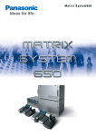
Matrix System650
Matrix System 650 uses simple components to give you fully
integrated control of up to 256 cameras and 32 monitors.
And is expandable up to 512 inputs by 64 outputs.
On screen menu to set Camera Title and Camera Position.
Camera
WJ-SX650 Series Administrator Console
The user-friendly GUI interface is designed to maximize usability and is available
in any of 8 languages: English, French, Spanish, German, Italian, Russian,
Chinese, Japanese.
Matrix System 650 from Panasonic is the new, easier way to configure mid-sized to large surveillance systems. This remarkable new
system makes it simple to fully integrate up to 256 cameras, 32 monitors, and 60 registered users.* Adding WJ-HD300A Series
Digital Disk Recorders delivers the high image quality and high storage capacity that state-of-the-art surveillance requires.
Matrix System 650’s simple, flexible architecture makes it ideal for a wide range of applications including
shopping malls, sporting venues, multipurpose complexes, office buildings and banks. * 1 of the 60 users is reserved for recorder control.
Main Menu
Tips Feature Supports Set Up
To see an explanation and set-up tips, simply
place the cursor over any of the buttons.
Menu sets Timer Events
and Camera Event.
Schedule
Sequence
The CSV format Export/Import feature
allows use of spreadsheet software to
organize setup data.
Major Features and Functions
Cameras
•
• All 256 channels are coaxial, multiplex cables, reducing the number of cables required and simplifying installation.
• Supports up to 256 RS-485, remote-controlled cameras.
• Pan, tilt and other lens motions can be controlled either by multiplex data over coaxial cable or RS-485 remote-control signals.
• Cables can be up to 900 m (3,000 feet) long (RG59/U coaxial cable, Belden 9259 or equivalent).
S y s t e m
• The maximum size (256 camera x 32 monitor) system requires four WJ-SX650/SX650U units.
• Set up is simple with the Video Input and Video Output Boards, each composed of a
Supports up to 256 cameras (using 8 Video Input Boards).
front-access Main Board and rear-access Rear Boards.
• Front access for Main Board and Power Supply maintenance.
• Rich array of sequence, alarm, and scheduling features meet every surveillance need.
• Supports up to 1,024 alarm inputs (Terminal/Camera/Recorder/Serial/Video Loss)
and up to 64 alarm outputs (and 1,024 Serial Alarm Out).
• Storage for up to 10,000 alarms, with downloadable alarm histories direct to PC.
• Easy Set-up with simple menu and WJ-SX650 Administrator Console.
• Up to 60 users* can be managed with individual priority and level settings.
Monitors
Recorders
(WJ-HD300A Series)
Controllers
2
• Output support for up to 32 monitors (using 2 Video Output Boards).
• Character displays show date, time, camera number, camera title and event information.
• Set-up menus are available in seven languages: English, French, Spanish, German, Italian, Russian, and Japanese.
• Alarm history displays up to 1,000 alarms.
• Supports connection of up to 16 WJ-HD300A Series recorders (using 2 Video Output Boards).
• Use of WJ-HD300A Series network features allow remote surveillance from a PC.
• Supports simultaneous use of up to 16 WV-CU650 System Controllers + personal computer (PC).
• Supports use of PS • Data (With DATA1 port set to PS • Data).
The calendar supports schedule
construction and review in yearly,
monthly, or weekly units.
Set Tour Sequence and Group Sequence/Group presets.
Large Scale System Expansion and Satellite Configuration.
The WJ-SX650 Matrix Switcher has been scaled up
for large-sized surveillance systems. It is now possible
to configure an expanded full matrix by interconnecting
matrix switchers, or configure satellites at remote
locations.
Up to six WJ-SX650 Systems can be controlled by
one WJ-MPU955A through Ethernet
Each WJ-SX650 system is connected by Video Link or Loop
Through (Video link and Loop through should be one hop)
Maximum 512 Cameras and 64 Monitors non-blocking
matrix system
Only the WV-CU950 system controller can be used in
the 512 x 64 system
The WJ-ASC960 software is only required for the satellite system
An expanded full matrix configuration enables the setup of a large-sized system
The system can be expanded to 512 cameras and 64 monitors.
Connect up to 64 domains in a satellite configuration.
Up to 64 domains can be networked by integrating an expanded full matrix
configuration consisting of up to 512 cameras and up to 64 monitors as one domain.
Up to 512 cameras x up to 64 monitors
Domain1
2
3
Domain64
Control via
IP Network
3
Matrix System 650 uses simple components to give you fully
integrated control of up to 256 cameras and 32 monitors.
And is expandable up to 512 inputs by 64 outputs.
On screen menu to set Camera Title and Camera Position.
Camera
WJ-SX650 Series Administrator Console
The user-friendly GUI interface is designed to maximize usability and is available
in any of 8 languages: English, French, Spanish, German, Italian, Russian,
Chinese, Japanese.
Matrix System 650 from Panasonic is the new, easier way to configure mid-sized to large surveillance systems. This remarkable new
system makes it simple to fully integrate up to 256 cameras, 32 monitors, and 60 registered users.* Adding WJ-HD300A Series
Digital Disk Recorders delivers the high image quality and high storage capacity that state-of-the-art surveillance requires.
Matrix System 650’s simple, flexible architecture makes it ideal for a wide range of applications including
shopping malls, sporting venues, multipurpose complexes, office buildings and banks. * 1 of the 60 users is reserved for recorder control.
Main Menu
Tips Feature Supports Set Up
To see an explanation and set-up tips, simply
place the cursor over any of the buttons.
Menu sets Timer Events
and Camera Event.
Schedule
Sequence
The CSV format Export/Import feature
allows use of spreadsheet software to
organize setup data.
Major Features and Functions
Cameras
•
• All 256 channels are coaxial, multiplex cables, reducing the number of cables required and simplifying installation.
• Supports up to 256 RS-485, remote-controlled cameras.
• Pan, tilt and other lens motions can be controlled either by multiplex data over coaxial cable or RS-485 remote-control signals.
• Cables can be up to 900 m (3,000 feet) long (RG59/U coaxial cable, Belden 9259 or equivalent).
S y s t e m
• The maximum size (256 camera x 32 monitor) system requires four WJ-SX650/SX650U units.
• Set up is simple with the Video Input and Video Output Boards, each composed of a
Supports up to 256 cameras (using 8 Video Input Boards).
front-access Main Board and rear-access Rear Boards.
• Front access for Main Board and Power Supply maintenance.
• Rich array of sequence, alarm, and scheduling features meet every surveillance need.
• Supports up to 1,024 alarm inputs (Terminal/Camera/Recorder/Serial/Video Loss)
and up to 64 alarm outputs (and 1,024 Serial Alarm Out).
• Storage for up to 10,000 alarms, with downloadable alarm histories direct to PC.
• Easy Set-up with simple menu and WJ-SX650 Administrator Console.
• Up to 60 users* can be managed with individual priority and level settings.
Monitors
Recorders
(WJ-HD300A Series)
Controllers
2
• Output support for up to 32 monitors (using 2 Video Output Boards).
• Character displays show date, time, camera number, camera title and event information.
• Set-up menus are available in seven languages: English, French, Spanish, German, Italian, Russian, and Japanese.
• Alarm history displays up to 1,000 alarms.
• Supports connection of up to 16 WJ-HD300A Series recorders (using 2 Video Output Boards).
• Use of WJ-HD300A Series network features allow remote surveillance from a PC.
• Supports simultaneous use of up to 16 WV-CU650 System Controllers + personal computer (PC).
• Supports use of PS • Data (With DATA1 port set to PS • Data).
The calendar supports schedule
construction and review in yearly,
monthly, or weekly units.
Set Tour Sequence and Group Sequence/Group presets.
Large Scale System Expansion and Satellite Configuration.
The WJ-SX650 Matrix Switcher has been scaled up
for large-sized surveillance systems. It is now possible
to configure an expanded full matrix by interconnecting
matrix switchers, or configure satellites at remote
locations.
Up to six WJ-SX650 Systems can be controlled by
one WJ-MPU955A through Ethernet
Each WJ-SX650 system is connected by Video Link or Loop
Through (Video link and Loop through should be one hop)
Maximum 512 Cameras and 64 Monitors non-blocking
matrix system
Only the WV-CU950 system controller can be used in
the 512 x 64 system
The WJ-ASC960 software is only required for the satellite system
An expanded full matrix configuration enables the setup of a large-sized system
The system can be expanded to 512 cameras and 64 monitors.
Connect up to 64 domains in a satellite configuration.
Up to 64 domains can be networked by integrating an expanded full matrix
configuration consisting of up to 512 cameras and up to 64 monitors as one domain.
Up to 512 cameras x up to 64 monitors
Domain1
2
3
Domain64
Control via
IP Network
3
MAJOR FUNCTIONS
A Rich Array of Features for More Reliable and Efficient Surveillance
Three Sequencing Features for More Efficient Monitoring
Schedules for Simple, Certain Operation
These features allow you to determine the sequence in which you see images from multiple cameras. System Controller buttons
make monitoring more efficient by enabling instant selection of the pattern of your choice.
Monitors and cameras can be automatically activated at preset dates and times using Daily, Weekly, and Monthly modes.
Timer Events
Camera Events
Tour Sequence
Group Sequence
Automatically switches camera images in preset sequences on the
monitor you select. You can preset up to 32 patterns with as many as
64 steps per pattern.
Automatically switches camera images in preset sequences on up to 16
pre-selected monitors at once. You can preset up to 8 patterns with as
many as 32 steps per pattern.
Spot, Tour Sequence and Group Sequence/Group Preset features
can be automatically activated on designated monitors, following
preset schedules. Up to 128 timer events can be registered and
assigned priorities.
Designated cameras can be set for automatic tracking*, B/W switching
and scene switching [PATROL(S)]*, and cleaning, following preset
schedules. Up to 128 camera events can be registered.
step 1
Tour 1
M1
step 2
C1
C2
step 3
C3
Group Sequence 8
step 64
Group Sequence 2
Group Sequence 1
C16
Tour 2
C5
C6
C7
ACTIVE PERIOD DESIGNATION
TIME
SCHEDULE MODE
ACTION
MONITOR
PRIORITY
1
JUL.19.2005 ~ JUL.23.2005
9:00 ~ 16:00
DAILY
TOUR SEQ
1 ~ 32
1 ~ 99
2
Always Active
10:00 ~ 17:00
WEEKLY (SUN)
GROUP SEQ
1 ~ 32
1 ~ 99
3
JAN.1.2005 ~ DEC.1.2005
22:00 ~ 01:00
MONTHLY (1)
CAMERA CLEANING
—
—
C1
C20
C5
C15
step 1
C9
C10
C11
C8
Tour 32
C13
C14
C15
C12
DEC.1.2005 ~ DEC.23.2005
12:00 ~ 17:00
MONTHLY (1)
GROUP PRESET
All 256 channels with multiplex data over coaxial cables
Monitor 1
Monitor 2
Monitor 3
Monitor 16
Group Preset
Allows instant spot display of selected camera images on up to 16 preselected monitors at once. You can preset up to 24 patterns.
Set switching interval and other parameters for each step
Setting
Group Preset 2
Group Preset 1
C1
C20
Monitor 1
Monitor 2
C5
C15
Monitor 3
Content
Note
Camera Number*
001 - 999
Your choice for up to 256 cameras
Preset*
001 - 256
Preset positions for combination cameras
AUX. 1/2
ON / OFF
To operate buzzers or other external devices
Dwell Time**
0 - 30 sec.
Image switching interval
* Can also be set using pre-registered camera position numbers.
** Not available for Group Preset since switching is occurs once.
Monitor 16
VD2 Compatible Panasonic Camera List
Operator Registration
B/W Cameras
WV-BP330 Series, WV-BP140 Series
Color Cameras
WV-CW484 Series, WV-CW244 Series,
OPE
1
Level 1
WV-CW374, WV-CL920A Series,
System Setup
OSD Control
Alarm History Display
System Status Display
WV-CP254H, WV-CP280 Series
Integrated Dome Cameras
WV-CS954, WV-CW964, WV-CS574
Timing Pulse (VD2) for Vertical Genlock
256
SPOT
Preset
1
Monitors
5
Recording
Source
10
Alarm Output
50
Alarm events can be displayed in Spot, Tour Sequence,
Group Sequence or Group preset modes.
Alarm Output 50
Preset Position 1
(Zoom in to Entrance 1)
Buzzer/Light
Terminal
Alarm 256
Records the image
of Camera 10
Monitor 5
(Recording follows the
command alarm setting
and event recording
setting of recorder.)
Three Alarm Modes (Spot Display Only)
Choose any of three ways to display multiple alarm
event images in Spot display mode.
Sequence mode ------ Alarm event images displayed on monitor in
the sequence in which they occurred.
Latest mode ---------------- Show latest alarm event image (Hold Last).
Earliest mode ------------ Show earliest alarm event image (Hold First).
(When alarms occur with Tour Sequence or Group Sequence/Group Preset set,
Sensor
earlier alarms are reset on that monitor.)
WJ-HD300A
Series
Sensor
System
4
Alarm
Notification
PC
Alarm
Vertical Blanking
High image quality and high capacity storage
When connected to the Panasonic WJ-HD300A Series
"Digital Disk Recorder", the Matrix System 650 can be used
to construct surveillance systems that offer both high image
quality and high capacity storage. WJ-HD300A Series Digital
Disk Recorders can be operated seamlessly from Matrix
System 650’s WV-CU650 System Controller,
to support multi-screen live monitoring and high-speed
Filtered Search. These digital disk recorders’ networking
features also allow remote control from a PC.
Log Up to 10,000 Alarms
ZOOM
Infrared
Sensor
OPE
6
21233
22342
Priority
Level 2
OSD Control
Alarm History Display
Password
OPE
7
OPE
16
31256
34682
Alarm Suspension
Level 3
Alarms All Reset
Alarms All Reset
Alarm ACK, Alarm
Alarm ACK, Alarm
Alarm ACK, Alarm
Individual/Monitor Reset Individual/Monitor Reset Individual/Monitor Reset
Start Tour Sequence
Start Group Sequence
Start Tour Sequence
Start Group Sequence
Monitor Lock
Monitor Lock
Camera Setup
Preset Position Registration
All Cameras Control
Camera Control
Camera Selection
Preset Position Registration
All Cameras Control
Camera Control
Camera Control
Camera Selection
Camera Selection
Recorder Setup
Recorder Control
Recorder Control
OPE
17
OPE
35
34397
31625
Level 4
Start Tour Sequence
Start Tour Sequence
Start Group Sequence Start Group Sequence
OPE
36
OPE
60
39262
33681
Level 5
Camera Selection
Camera Selection
Recorder Control
OPERATOR’S LEVEL TABLE
Used to schedule pre-registered alarm events (ON/OFF,
daily, weekly, monthly).
Four Display Modes
WJ-SX650
Matrix Switcher to Camera
Video
Alarm Schedule for up to 64 Alarms
Camera 100
Entrance 1
Data 8-bit x 4
OPE
2
12123
WV-CF294/284 Series, WV-CP480 Series,
Preset camera positions, sequences and recording can be automatically activated by all types of alarm signals (Terminal, Camera,
Recorder, Serial, Video Loss). Register up to 1,024 Alarm Events.
SPOT
Camera Number
100
WV-CS954
Up to 60 users* can be registered with individual user IDs and
passwords. Security can be fine-tuned with individual level,
priority and camera/recorder display and operation restrictions,
to guard against unauthorized access and unauthorized
changes in settings.
* 1 of the 60 users is reserved for recorder control.
Camera to Matrix Switcher
Display Mode
1 ~ 99
To simplify installation and for smoother system expansion,
video signals, control data, synchronous signals (VD2) and
alarm signals are all transmitted over the same coaxial cable.
Cables can be up to 900 m (3,000 feet) long (RG59/U coaxial
cable, Belden 9259 or equivalent).
Up to 1,024 Alarm Events Ensure That You Capture Vital Scenes
No.
1 ~ 32
Preventing unauthorized access
Since 1988, most of Panasonic cameras have been designed and manufactured to accept VD2 signal for system integration.
For example: Terminal Alarm Event No.256
Super Dynamic III
Color Dome Camera
•
•
•
128
The images can be
seen on any monitor.
Group Preset 24
The Camera You Need
to Take Full Advantage
of Camera Events
(ALL CAMERA)
C4
Tour 3
Camera Event
PROGRAM
step 32
M32
* For only limited models.
Timer Event
The image shifts automatically from one camera to another, as programmed.
Matrix System 650 can store up to 10,000 alarm events.
Alarm histories can downloaded to a PC for analysis and
management. The latest 1,000 alarm events can be
viewed from a surveillance monitor.
Digital Disk Recorders
WJ-HD300A Series
Rich array of display options
Use of a newly developed LSI allows you to choose from any
of seven languages (English, French, Spanish, German,
Example of Character Displays
Italian, Russian, or Japanese)
when setting up a system.
When monitoring date and
time, camera title, monitor
status, and event information
can all be displayed. Camera
titles can include roman
alphabet, special alphabet
Custom Character
(German or Russian),
numbers, symbols, and
13
Chinese and Japanese
15
characters (approx. 1,000).
You can create up to 32 custom characters.
5
MAJOR FUNCTIONS
A Rich Array of Features for More Reliable and Efficient Surveillance
Three Sequencing Features for More Efficient Monitoring
Schedules for Simple, Certain Operation
These features allow you to determine the sequence in which you see images from multiple cameras. System Controller buttons
make monitoring more efficient by enabling instant selection of the pattern of your choice.
Monitors and cameras can be automatically activated at preset dates and times using Daily, Weekly, and Monthly modes.
Timer Events
Camera Events
Tour Sequence
Group Sequence
Automatically switches camera images in preset sequences on the
monitor you select. You can preset up to 32 patterns with as many as
64 steps per pattern.
Automatically switches camera images in preset sequences on up to 16
pre-selected monitors at once. You can preset up to 8 patterns with as
many as 32 steps per pattern.
Spot, Tour Sequence and Group Sequence/Group Preset features
can be automatically activated on designated monitors, following
preset schedules. Up to 128 timer events can be registered and
assigned priorities.
Designated cameras can be set for automatic tracking*, B/W switching
and scene switching [PATROL(S)]*, and cleaning, following preset
schedules. Up to 128 camera events can be registered.
step 1
Tour 1
M1
step 2
C1
C2
step 3
C3
Group Sequence 8
step 64
Group Sequence 2
Group Sequence 1
C16
Tour 2
C5
C6
C7
ACTIVE PERIOD DESIGNATION
TIME
SCHEDULE MODE
ACTION
MONITOR
PRIORITY
1
JUL.19.2005 ~ JUL.23.2005
9:00 ~ 16:00
DAILY
TOUR SEQ
1 ~ 32
1 ~ 99
2
Always Active
10:00 ~ 17:00
WEEKLY (SUN)
GROUP SEQ
1 ~ 32
1 ~ 99
3
JAN.1.2005 ~ DEC.1.2005
22:00 ~ 01:00
MONTHLY (1)
CAMERA CLEANING
—
—
C1
C20
C5
C15
step 1
C9
C10
C11
C8
Tour 32
C13
C14
C15
C12
DEC.1.2005 ~ DEC.23.2005
12:00 ~ 17:00
MONTHLY (1)
GROUP PRESET
All 256 channels with multiplex data over coaxial cables
Monitor 1
Monitor 2
Monitor 3
Monitor 16
Group Preset
Allows instant spot display of selected camera images on up to 16 preselected monitors at once. You can preset up to 24 patterns.
Set switching interval and other parameters for each step
Setting
Group Preset 2
Group Preset 1
C1
C20
Monitor 1
Monitor 2
C5
C15
Monitor 3
Content
Note
Camera Number*
001 - 999
Your choice for up to 256 cameras
Preset*
001 - 256
Preset positions for combination cameras
AUX. 1/2
ON / OFF
To operate buzzers or other external devices
Dwell Time**
0 - 30 sec.
Image switching interval
* Can also be set using pre-registered camera position numbers.
** Not available for Group Preset since switching is occurs once.
Monitor 16
VD2 Compatible Panasonic Camera List
Operator Registration
B/W Cameras
WV-BP330 Series, WV-BP140 Series
Color Cameras
WV-CW484 Series, WV-CW244 Series,
OPE
1
Level 1
WV-CW374, WV-CL920A Series,
System Setup
OSD Control
Alarm History Display
System Status Display
WV-CP254H, WV-CP280 Series
Integrated Dome Cameras
WV-CS954, WV-CW964, WV-CS574
Timing Pulse (VD2) for Vertical Genlock
256
SPOT
Preset
1
Monitors
5
Recording
Source
10
Alarm Output
50
Alarm events can be displayed in Spot, Tour Sequence,
Group Sequence or Group preset modes.
Alarm Output 50
Preset Position 1
(Zoom in to Entrance 1)
Buzzer/Light
Terminal
Alarm 256
Records the image
of Camera 10
Monitor 5
(Recording follows the
command alarm setting
and event recording
setting of recorder.)
Three Alarm Modes (Spot Display Only)
Choose any of three ways to display multiple alarm
event images in Spot display mode.
Sequence mode ------ Alarm event images displayed on monitor in
the sequence in which they occurred.
Latest mode ---------------- Show latest alarm event image (Hold Last).
Earliest mode ------------ Show earliest alarm event image (Hold First).
(When alarms occur with Tour Sequence or Group Sequence/Group Preset set,
Sensor
earlier alarms are reset on that monitor.)
WJ-HD300A
Series
Sensor
System
4
Alarm
Notification
PC
Alarm
Vertical Blanking
High image quality and high capacity storage
When connected to the Panasonic WJ-HD300A Series
"Digital Disk Recorder", the Matrix System 650 can be used
to construct surveillance systems that offer both high image
quality and high capacity storage. WJ-HD300A Series Digital
Disk Recorders can be operated seamlessly from Matrix
System 650’s WV-CU650 System Controller,
to support multi-screen live monitoring and high-speed
Filtered Search. These digital disk recorders’ networking
features also allow remote control from a PC.
Log Up to 10,000 Alarms
ZOOM
Infrared
Sensor
OPE
6
21233
22342
Priority
Level 2
OSD Control
Alarm History Display
Password
OPE
7
OPE
16
31256
34682
Alarm Suspension
Level 3
Alarms All Reset
Alarms All Reset
Alarm ACK, Alarm
Alarm ACK, Alarm
Alarm ACK, Alarm
Individual/Monitor Reset Individual/Monitor Reset Individual/Monitor Reset
Start Tour Sequence
Start Group Sequence
Start Tour Sequence
Start Group Sequence
Monitor Lock
Monitor Lock
Camera Setup
Preset Position Registration
All Cameras Control
Camera Control
Camera Selection
Preset Position Registration
All Cameras Control
Camera Control
Camera Control
Camera Selection
Camera Selection
Recorder Setup
Recorder Control
Recorder Control
OPE
17
OPE
35
34397
31625
Level 4
Start Tour Sequence
Start Tour Sequence
Start Group Sequence Start Group Sequence
OPE
36
OPE
60
39262
33681
Level 5
Camera Selection
Camera Selection
Recorder Control
OPERATOR’S LEVEL TABLE
Used to schedule pre-registered alarm events (ON/OFF,
daily, weekly, monthly).
Four Display Modes
WJ-SX650
Matrix Switcher to Camera
Video
Alarm Schedule for up to 64 Alarms
Camera 100
Entrance 1
Data 8-bit x 4
OPE
2
12123
WV-CF294/284 Series, WV-CP480 Series,
Preset camera positions, sequences and recording can be automatically activated by all types of alarm signals (Terminal, Camera,
Recorder, Serial, Video Loss). Register up to 1,024 Alarm Events.
SPOT
Camera Number
100
WV-CS954
Up to 60 users* can be registered with individual user IDs and
passwords. Security can be fine-tuned with individual level,
priority and camera/recorder display and operation restrictions,
to guard against unauthorized access and unauthorized
changes in settings.
* 1 of the 60 users is reserved for recorder control.
Camera to Matrix Switcher
Display Mode
1 ~ 99
To simplify installation and for smoother system expansion,
video signals, control data, synchronous signals (VD2) and
alarm signals are all transmitted over the same coaxial cable.
Cables can be up to 900 m (3,000 feet) long (RG59/U coaxial
cable, Belden 9259 or equivalent).
Up to 1,024 Alarm Events Ensure That You Capture Vital Scenes
No.
1 ~ 32
Preventing unauthorized access
Since 1988, most of Panasonic cameras have been designed and manufactured to accept VD2 signal for system integration.
For example: Terminal Alarm Event No.256
Super Dynamic III
Color Dome Camera
•
•
•
128
The images can be
seen on any monitor.
Group Preset 24
The Camera You Need
to Take Full Advantage
of Camera Events
(ALL CAMERA)
C4
Tour 3
Camera Event
PROGRAM
step 32
M32
* For only limited models.
Timer Event
The image shifts automatically from one camera to another, as programmed.
Matrix System 650 can store up to 10,000 alarm events.
Alarm histories can downloaded to a PC for analysis and
management. The latest 1,000 alarm events can be
viewed from a surveillance monitor.
Digital Disk Recorders
WJ-HD300A Series
Rich array of display options
Use of a newly developed LSI allows you to choose from any
of seven languages (English, French, Spanish, German,
Example of Character Displays
Italian, Russian, or Japanese)
when setting up a system.
When monitoring date and
time, camera title, monitor
status, and event information
can all be displayed. Camera
titles can include roman
alphabet, special alphabet
Custom Character
(German or Russian),
numbers, symbols, and
13
Chinese and Japanese
15
characters (approx. 1,000).
You can create up to 32 custom characters.
5
PRODUCT CONFIGURATION
OPTION UNIT FOR EXPANSION & SATELLITE
Matrix Switcher: WJ-SX650 / Card Cage: WJ-SX650U
Central Processing Unit: WJ-MPU955A
Front View
WJ-SX650/WJ-SX650U (Front Panel detached)
WJ-SX650/WJ-SX650U (Front Panel attached)
SPECIFICATIONS
Front View
Matrix Switcher: WJ-SX650
<Front panel attached>
420(16-9/16")
Power Source
120 V AC, 60 Hz
Power Consumption
60 W
88 (3 - 7/16")
265(10-7/16")
MODE
PULL
Video Input Board
x1
Video Output Board
x1
Expansion Slot
x1
RS-485 (Camera) Port
termination switches (MODE 1 to 4))
POWER
OPERATE LED WILL BLINK
IF COOLING FAN MALFUNCTIONS
ON
Functions
OFF
TEST
RESET
Matrix Switcher WJ-SX
6-conductor modular jack x 4
(2-wire or 4-wire communication, With
OPERATE
<Front panel detached>
Monitor control (Camera selection, tour
MODE
sequence, group sequence, group preset,
650
OSD display) , Camera/Receiver control
(Coaxial/RS-485 communication), Recorder
control, Alarm control (Alarm event, Alarm
479(18-7/8")
Rear View
ACK, Alarm reset, Alarm suspension, Alarm
History Display), Timer event, Camera event
WJ-SX650U
WJ-SX650
4
2
3
1
4
C
RS485 (CAMERA)
MODE
MODE
RS485 (CAMERA)
MODE
2
1
RS485 (CAMERA)
MODE
MODE
RS485 (CAMERA)
MODE
VIDEO OUT 1
VIDEO OUT 2
32
31
30
29
28
27
26
16
15
14
13
12
11
10
25
24
23
8
7
IN X-2
ALARM IN
22
21
20
5
4
19
18
17
3
2
1
SIGNAL GND
IN C-3
MODE
RS485(CAMERA) SET UP
RS485(CAMERA) SET UP
4-Line
1
1
2
3
RS485 (CAMERA)
MODE
RS485 (CAMERA)
MODE
1
2
3
MODE
MODE
RS485 (CAMERA)
Expansion Slot
2
DATA 3
HDR2/TMNL4 HDR1/TMNL3
15
14
DATA 2
DATA 1
TMNL6
TMNL5
TMNL2
TMNL1/PS DATA
13
12
TERM.ON
ON
4
TERM.OFF
3
2
1
OFF
A
ON
OFF
AC IN
A
ON
MODE
MODE
10
9
DATA
MODE
8
7
MODE
6
DATA
MODE
5
4
EXTENSION 1 IN
OUT
3
TERM.
EXTENSION 3 OUT
OUT X-3
2
1
EXTENSION 2 OUT
RS485 (CAMERA)
MODE
MODE
MODE
RS485 (CAMERA)
OUT
MODE
EXTENSION 1 IN
TERM.
2
Extension Port
OUT X-2
MONITOR OUT
VS IN
VS OUT
SERIAL
SIGNAL GND
1
Video Output Board 1 Only
VS OUT
(THRU)
ALARM OUT 1
ALARM OUT 2
" " 1
6-conductor modular jack x 2 (With a
(EXTENSION 1 IN, OUT) termination switch (TERM: ON, OFF))
SIGNAL GND
SPECIFICATIONS
OUT X-1
Extension Port
37-pin D-sub connector x 2
Operation Indicator
Front Panel Fixing Screws
Power Switch
Expansion Slot
Video Input Board
Video Output Board
Video Input Board Rear Panels
Expansion Slot
Dimensions (W x H x D)
RESET No.
Ethernet Port
VIDEO OUT 3
VIDEO OUT 1
VIDEO OUT 2
32
31
30
29
28
27
26
16
15
14
13
12
11
10
0.5 V [P-P]/75 Ω data signal and
Video Output
1 V [P-P]/75 Ω (25-pin D-sub connector x 4),
25
IN X-2
ALARM IN
24
23
22
21
20
19
18
17
9
CAMERA IN
8
7
6
5
4
3
2
1
IN X-1
(VIDEO OUT 1 to 4)
active loop-thru output
Alarm Input
N.O. (Normally Open contact) or
(ALARM IN)
N.C. (Normally Close contact) selectable x 32 (37-pin D-sub connector)
MAJOR OPERATING CONTROLS
Top View
Main Board
346 mm x 42 mm x 225 mm [13-3/5" x 1-3/5" x 8-4/5"]
IN X-2 Board
355 mm x 21 mm x 115 mm [14" x 4/5" x 4-1/2"]
IN X-1 Board
355 mm x 38 mm x 115 mm [14" x 1-1/2" x 4-1/2"]
Board Number Switch
Input Mode Selection Switches
Reset Switch
Video Output Ports 1 to 4
Alarm Input Port
Camera Input Connectors 1 to 32
SPECIFICATIONS
Front View
Monitor Output
TEST
RESET
MODE
Data Port (DATA 1 to 4)
DATA 1
Rear View
Terminal Mode (TMNL)/PS • Data (PS • DATA) selectable
DATA 2
Terminal Mode (TMNL)
DATA 3, 4
Terminal Mode (TMNL)/Digital disk recorder (HDR) selectable
6-conductor modular jack x 4
DATA 4
OUT X-2 Board
1 V [P-P]/75 Ω (BNC x 16)
(MONITOR OUT 1 to 16)
Main Board
16
DATA 3
15
14
DATA 2
DATA 1
TMNL6
TMNL2
TMNL1/PS DATA
13
TERM.ON
ON
4
TERM.OFF
3
2
1
OFF
(With termination switches (MODE 1 to 4))
ON
TMNL5
12
MODE
11
MODE
10
MODE
9
DATA
8
MODE
7
DATA
MODE
6
MODE
5
4
OUT
EXTENSION 1 IN
3
TERM.
2
OUT X-3
1
OUT X-2
MONITOR OUT
Alarm Output (ALARM OUT 1, 2)
Alarm Output
Open collector output x 32, Max. 24 V DC, 100 mA
Alarm Recover Input
Non-voltage make contact input x 16
Time Adjust Input
Non-voltage make contact input x 1
Time Adjust Output
Open collector output x 32, Max. 24 V DC, 100 mA
Extension Port
(EXTENSION 1 IN, OUT)
.
VS IN
OUT X-1 Board
Video Output Board 1 Only
ALARM OUT 2
ALARM OUT 1
VS OUT
(THRU)
VS OUT
SERIAL
6-conductor modular jack x 2
(With a termination switch (TERM: ON, OFF))
VS Input
1 V [P-P]/75 Ω (VS IN)
VS Output
(VS OUT (THRU)): VS loop-thru output,
OUT X-1
(VS OUT): 1 V [P-P]/75 Ω (VS)
Serial Port
9-pin D-sub connector x 2
Dimensions (W x H x D)
Output Mode Selection Switches
Reset Switch
Test Port
Extension Ports 1
Termination Selector
6
Data Ports 3, 4
Data Ports 1, 2
Rear Termination
MODE Switches 1 to 4
Monitor Output Connectors
Alarm Output Ports 1,2
VS Input Connector
VS Output Loop-thru Connector
VS Output Connector
Serial Port
" VS Output
(VS OUT (THRU)): VS loop-thru output
4 "-$ >(# >7 +$$ 3
( )3$ ?A &
" " " #$ %&
"'()
?@6
+(,
# -
(, !# .) #
(, !# /) #
0 0, #
1 2 & 0)' 3$ 2 4
"35% !# 3$
!
0, 6' $$ 44
78 " 5 9# :; +(,<
(, "-$ "'= >(#
:; >(#<
4 3$ $-, #)#' , (- $6&
4 % 3 ; ($$ #)#' '6' (;-&
!
9-pin D-sub connector x 1
Ethernet Controller: WV-CU950
Video Output Board: WJ-PB65M16
HDR4/TMNL8 HDR3/TMNL7
HDR2/TMNL4 HDR1/TMNL3
1 V [P-P]/75 Ω (VS IN)
1 V [P-P]/75 Ω (BNC x 32), composite video signal
IN X-1 Board
Video Output Board 1
Dimensions (W x H x D) 355 mm x 38 mm x 134 mm [14" x 1-1/2" x 5-3/10"]
Dimensions (W x H x D)
IN X-2 Board
Video Output Board 2
VS Input
2.5 V [P-P]/75 Ω vertical timing pulse multiplexed
Rear View
OUT X-3 Board
10Base-T/100Base-TX, RJ-45 x 1
Alarm Output Port 1, 2 Open collector output x 32, Max. 24 V DC, 100 mA
18.0 kg (40 lbs.)
Serial Port
MODE
VIDEO OUT 4
SPECIFICATIONS
(CAMERA IN 1 to 32)
SPECIFICATIONS
(excluding rubber feet and projections)
Camera Input
(VS OUT): 1 V [P-P]/75 Ω (VS)
Front View
420 mm x 265 mm x 372 mm
[16-9/16" x 10-7/16" x 14-3/5"]
Weight
37-pin D-sub connector x 2
Video Input Board: WJ-PB65C32
Main Board
(EXTENSION OUT 2, 3)
Video Output Board Rear Panels
AC Inlet Socket
Signal Ground Terminal
(EXTENSION IN 2, 3)
Extension Port
Ethernet Port
Alarm Output Ports 1,2
VS Input Connector
VS Output Loop-thru Connector
VS Output Connector
Serial Port
6-conductor modular jack x 12
termination switches (MODE 1 to 4))
IN A-3
2
x3
AC IN
3
3
MODE
11
" " (2-wire or 4-wire communication, With
1
1
DATA 4
HDR4/TMNL8 HDR3/TMNL7
16
19.0 kg (42 lbs.)
RS-485 (Camera) Port
Video Output Board 1
Card Cage: WJ-SX650U
MODE
B
IN B-3
MODE
2
Video Output Board 2
3
RS485 (CAMERA)
MODE
IN B-3
MODE
ON
4
B
3
MODE
4-Line
1
MODE
IN X-1
4
420 (16-9/16")
Rear View
MODE
MODE
ON
4-Line
6
Weight
ON
ON
4-Line
9
CAMERA IN
Rear View
(excluding rubber feet and projections)
2
2
VIDEO OUT 3
VIDEO OUT 4
420 mm x 265 mm x 372 mm
Operation Indicator
Screws
Fan Alarm Indicator
Hard Disk Drive Indicator
Active Indicator
Operation Switch
Redundant Selector
Mode Selector
Reset Button
Test ports
Ethernet Ports
Peripheral Interface Ports
Cooling Fan Unit
Power Switch
AC Inlet Socket
[16-9/16" x 10-7/16" x 14-3/5"]
C
3
EXTENSION 2 IN
EXTENSION 3 IN
IN C-3
MODE
3
SIGNAL GND
3
EXTENSION 2 IN
EXTENSION 3 IN
Dimensions (W x H x D)
An expanded full matrix configuration for a maximum 512-camera x 64-output system.
481.2 (18-15/16")
Ambient Operating Humidity Less than 90 %
No.
1
Front View
Ambient Operating Temperature –10 °C to +50 °C (14 °F to 122 °F)
RESET
Network Board: WJ-PB65E01
SYSTEM EXAMPLES FOR EXPANSION & SATELLITE
Main Board
346 mm x 42 mm x 225 mm [13-3/5" x 1-3/5" x 8-4/5"]
OUT X-3 Board
355 mm x 21 mm x 115 mm [14" x 4/5" x 4-1/2"]
OUT X-2 Board
355 mm x 21 mm x 115 mm [14" x 4/5" x 4-1/2"]
OUT X-1 Board
355 mm x 38 mm x 115 mm [14" x 1-1/2" x 4-1/2"]
Rear View
1
2
3
4
5
6
7
8
9
10
11
12
13
14
15
16
17
18
19
20
21
22
23
24
25
26
27
28
29
30
31
32
Operation Indicator
Alarm Indicator
Alarm Suspend Indicator
Shift Button
Clear Button
Alarm Reset/Alarm All Reset Button
Alarm Acknowledge Button
Alarm/Alarm Suspend Button
Camera Function/System Function Button
Alarm Recall Button
On-Screen Display Button
Monitor Lock/Logout Button
Tour Sequence/Group Sequence Button
Sequence Pause/Sequence Stop Button
Go To Last Button
Electronic Zoom Button
Multiscreen Selection Button
Mark Button
Auxiliary 2 ON/OFF Button
Auxiliary 1 ON/OFF Button
Search/Time and Date Search Button
Defroster Button
Wiper Button
Stop Button
Play/Pause Button
Recording Button
Shuttle Ring (Outside)/JogDial (Inside)
Shuttle Hold Button
History Button
- Button
+ Button
Recorder/Unit Selection Button
33
34
35
36
37
38
39
40
41
42
43
44
45
46
47
48
49
50
51
52
53
54
55
56
57
58
2
Preset/Program Preset Button
Camera Position Button
Numeric Buttons
Monitor/Escape Button
Camera/Set Button
LCD
Adjustment Button
Menu Button
Function Buttons
Exit Button
Enter Button
Feet
Joystick Connector
Serial Port
Data Ports
Mode Selection Switches
Controller Number Switch
DC 9V Input Jack
Ethernet Port
Top Button
Zoom Wheel Controller
Iris Control Buttons
Focus Control Buttons
A and B Buttons
3D Joystick
Adjusting Screw
.2 /1
./7 2/1
-2
./ + 0/1
.2 /1
-/
./ + 0/1
-0
. + 0/1
-
./ + 0/1
#&
9 V DC, 600 mA (using the supplied AC adapter)
120 V AC, 60 Hz, 200 mA
10Base-T/100Base-TX, RJ-45 x 1
6-conductor modular jack (RS-485, Full duplex) x 2
9-pin D-sub connector
1 to 8 (rotary switch)
!"
#
1 to 99
1 to 99
1 to 256
Main Unit: 290 mm x 111 mm x 221 mm [11-7/16" x 4-3/8" x 8-11/16"]
3D Joystick Unit: 134 mm x 146 mm x 218 mm [5-1/4" x 5-3/4" x 8-9/16"]
Weight (without the AC adapter) Main Unit: 1.3 kg (2.86 lbs.) 3D Joystick Unit: 0.8 kg (1.76 lbs.)
8
&#
-
./ + 0/1
&#
-
. + 0/1
-
. + 0/1
,&
#&
-0
. + 0/1
-
./ + 0/1
&#
-/
./ + 0/1
&#
&#
-
./ + 0/1
./7 2/1
-2
./ + 0/1
&#
SPECIFICATIONS
Power Source
Power Source (supplied AC adapter)
Ethernet Port
Data Output/Input Port
Serial Port
Controller Number
Ambient Operating Temperature
Unit Number Selection
Monitor Number Selection
Camera Number Selection
Dimensions (W x H x D)
Up to 64 domains can be connected in a satellite configuration.
!"
#
,&
#&
!"
#
!"
# $% #&
'(
) * +
,&
4 2*/ + / 5 4 2/ + 5 4 2*/ + / 5 4 2*/ + / 6 2*/ + / 5 4 2/ + 6 2*/ + / 5 9
SYSTEM EXAMPLES
1
Basic System
Camera (17) ~ (30)
Input Board (1)
HD316A (2)
4
3
2
Camera (1) ~ (16)
Cam (30)
1
+
25 ~ 30
HD316A (1)
2
1~8
9 ~ 16
16 15 14 13 12 11 10
+
SYSTEM
Camera ---- 30
Monitor ----- 16
HD316A ----- 2
Controller --- 6
PC ------------ 1
Operator ---- 4
17 ~ 24
32 31 30 29 28 27 26 25 24 23 22 21 20 19 18 17
9
8
7
6
5
4
3
2
1
HD316A (1) ~ (2) HDR
PS • DATA
Output Board (1)
Monitor (1) ~ (16)
4
16
15
14
13
12
11
10
9
8
3
2
7
6
1
5
4
3
2
1
Max.4
TMNL
TMNL
PC
Medium-sized System
Camera (113) ~ (120)
Input Board (4)
HD316A (8)
16 15
14 13
Camera (97) ~ (112)
Cam (113)
+
113 ~ 120
HD316A (7)
105 ~ 112
97 ~ 104
128 127 126 125 124 123 122 121 120 119 118 117 116 115 114 113
112 111 110 109 108 107 106 105 104 103 102 101 100 99 98 97
+
Input Board (2)
HD316A (4)
8
7
6
5
Camera (49) ~ (64)
Camera (33) ~ (48)
Camera (17) ~ (32)
Camera (1) ~ (16)
Cam (49)
+
57 ~ 64
HD316A (3)
49 ~ 56
33 ~ 40
41 ~ 48
64 63 62 61 60 59 58 57 56 55 54 53 52 51 50 49
48 47 46 45 44 43 42 41 40 39 38 37 36 35 34 33
+
Input Board (1)
HD316A (2)
4
3
2
1
Cam (32)
+
25 ~ 30
HD316A (1)
3
1~8
9 ~ 16
16 15 14 13 12 11 10
+
SYSTEM
Camera -- 120
Monitor ----- 16
HD316A ----- 8
Controller --- 5
PC ------------ 1
Operator ---- 3
17 ~ 24
32 31 30 29 28 27 26 25 24 23 22 21 20 19 18 17
9
8
7
6
5
4
3
2
1
HD316A (5) ~ (8) HDR
HD316A (1) ~ (4) HDR
PS • DATA
Output Board (1)
Monitor (1) ~ (16)
4
16
15
14
13
12
11
10
9
8
3
2
7
6
1
5
4
3
2
1
Max.4
TMNL
PC
Maximum-sized 256-camera System (Image playback is only possible on the monitors connected WJ-HD300A Series Digital Disk Recorders)
Camera (241) ~ (256)
Input Board (8)
HD316A (16)
32 31
30 29
Camera (225) ~ (240)
Cam (256)
+
249 ~ 256
HD316A (15)
241 ~ 248
233 ~ 240
225 ~ 232
256 255 254 253 252 251 250 249 248 247 246 245 244 243 242 241
240 239 238 237 236 235 234 233 232 231 230 229 228 227 226 225
+
HD316A (4)
Input Board (2)
8
7
6
5
Camera (49) ~ (64)
Camera (33) ~ (48)
Camera (17) ~ (32)
Camera (1) ~ (16)
Cam (49)
+
57 ~ 64
HD316A (3)
49 ~ 56
33 ~ 40
41 ~ 48
64 63 62 61 60 59 58 57 56 55 54 53 52 51 50 49
48 47 46 45 44 43 42 41 40 39 38 37 36 35 34 33
+
Input Board (1)
HD316A (2)
4
3
2
1
Cam (32)
+
25 ~ 30
HD316A (1)
17 ~ 24
9 ~ 16
1~8
32 31 30 29 28 27 26 25 24 23 22 21 20 19 18 17
16 15 14 13 12 11 10
+
9
8
7
6
5
4
3
2
1
HD316A (13) ~ (16) HDR
Max.4
Output Board (2)
Monitor (17) ~ (32)
HD316A (9) ~ (12) HDR
8
32
31
30
29
28
27
26
25
24
7
23
6
22
TMNL
5
21
20
19
18
17
Max.4
TMNL
HD316A (5) ~ (8) HDR
SYSTEM
Camera -- 256
Monitor ----- 32
HD316A --- 16
Controller -- 16
PC ------------ 1
Operator --- 17
4
Output Board (1)
Monitor (1) ~ (16)
HD316A (1) ~ (4) HDR
4
16
15
14
13
12
11
10
9
8
3
2
7
6
Max.4
1
5
TMNL
4
3
2
1
Max.4
TMNL
PC
WJ-HD300A Series Web Control System
Camera (17) ~ (30)
Internet
Input Board (1)
HD316A (2)
4
25 ~ 30
+
17 ~ 24
3
9 ~ 16
2
Camera (1) ~ (16)
Cam (30)
1
1~8
32 31 30 29 28 27 26 25 24 23 22 21 20 19 18 17
Internet
HD316A (1)
16 15 14 13 12 11 10
9
8
7
6
5
4
3
2
1
+
SYSTEM
Camera ---- 30
Monitor ----- 16
HD316A ----- 2
(Web Control)
Controller --- 6
PC ------------ 1
Operator ---- 4
HDR
Monitor (1) ~ (16)
control of HD316A from CU650
control of Camera from HD316A-Web
PS • DATA
Output Board (1)
4
16
15
14
13
12
11
10
9
8
3
7
2
6
5
1
4
3
2
1
TMNL
Max.4
TMNL
PC
7
PRODUCT CONFIGURATION
OPTION UNIT FOR EXPANSION & SATELLITE
Matrix Switcher: WJ-SX650 / Card Cage: WJ-SX650U
Central Processing Unit: WJ-MPU955A
Front View
WJ-SX650/WJ-SX650U (Front Panel detached)
WJ-SX650/WJ-SX650U (Front Panel attached)
SPECIFICATIONS
Front View
Matrix Switcher: WJ-SX650
<Front panel attached>
420(16-9/16")
Power Source
120 V AC, 60 Hz
Power Consumption
60 W
88 (3 - 7/16")
265(10-7/16")
MODE
PULL
Video Input Board
x1
Video Output Board
x1
Expansion Slot
x1
RS-485 (Camera) Port
termination switches (MODE 1 to 4))
POWER
OPERATE LED WILL BLINK
IF COOLING FAN MALFUNCTIONS
ON
Functions
OFF
TEST
RESET
Matrix Switcher WJ-SX
6-conductor modular jack x 4
(2-wire or 4-wire communication, With
OPERATE
<Front panel detached>
Monitor control (Camera selection, tour
MODE
sequence, group sequence, group preset,
650
OSD display) , Camera/Receiver control
(Coaxial/RS-485 communication), Recorder
control, Alarm control (Alarm event, Alarm
479(18-7/8")
Rear View
ACK, Alarm reset, Alarm suspension, Alarm
History Display), Timer event, Camera event
WJ-SX650U
WJ-SX650
4
2
3
1
4
C
RS485 (CAMERA)
MODE
MODE
RS485 (CAMERA)
MODE
2
1
RS485 (CAMERA)
MODE
MODE
RS485 (CAMERA)
MODE
VIDEO OUT 1
VIDEO OUT 2
32
31
30
29
28
27
26
16
15
14
13
12
11
10
25
24
23
8
7
IN X-2
ALARM IN
22
21
20
5
4
19
18
17
3
2
1
SIGNAL GND
IN C-3
MODE
RS485(CAMERA) SET UP
RS485(CAMERA) SET UP
4-Line
1
1
2
3
RS485 (CAMERA)
MODE
RS485 (CAMERA)
MODE
1
2
3
MODE
MODE
RS485 (CAMERA)
Expansion Slot
2
DATA 3
HDR2/TMNL4 HDR1/TMNL3
15
14
DATA 2
DATA 1
TMNL6
TMNL5
TMNL2
TMNL1/PS DATA
13
12
TERM.ON
ON
4
TERM.OFF
3
2
1
OFF
A
ON
OFF
AC IN
A
ON
MODE
MODE
10
9
DATA
MODE
8
7
MODE
6
DATA
MODE
5
4
EXTENSION 1 IN
OUT
3
TERM.
EXTENSION 3 OUT
OUT X-3
2
1
EXTENSION 2 OUT
RS485 (CAMERA)
MODE
MODE
MODE
RS485 (CAMERA)
OUT
MODE
EXTENSION 1 IN
TERM.
2
Extension Port
OUT X-2
MONITOR OUT
VS IN
VS OUT
SERIAL
SIGNAL GND
1
Video Output Board 1 Only
VS OUT
(THRU)
ALARM OUT 1
ALARM OUT 2
" " 1
6-conductor modular jack x 2 (With a
(EXTENSION 1 IN, OUT) termination switch (TERM: ON, OFF))
SIGNAL GND
SPECIFICATIONS
OUT X-1
Extension Port
37-pin D-sub connector x 2
Operation Indicator
Front Panel Fixing Screws
Power Switch
Expansion Slot
Video Input Board
Video Output Board
Video Input Board Rear Panels
Expansion Slot
Dimensions (W x H x D)
RESET No.
Ethernet Port
VIDEO OUT 3
VIDEO OUT 1
VIDEO OUT 2
32
31
30
29
28
27
26
16
15
14
13
12
11
10
0.5 V [P-P]/75 Ω data signal and
Video Output
1 V [P-P]/75 Ω (25-pin D-sub connector x 4),
25
IN X-2
ALARM IN
24
23
22
21
20
19
18
17
9
CAMERA IN
8
7
6
5
4
3
2
1
IN X-1
(VIDEO OUT 1 to 4)
active loop-thru output
Alarm Input
N.O. (Normally Open contact) or
(ALARM IN)
N.C. (Normally Close contact) selectable x 32 (37-pin D-sub connector)
MAJOR OPERATING CONTROLS
Top View
Main Board
346 mm x 42 mm x 225 mm [13-3/5" x 1-3/5" x 8-4/5"]
IN X-2 Board
355 mm x 21 mm x 115 mm [14" x 4/5" x 4-1/2"]
IN X-1 Board
355 mm x 38 mm x 115 mm [14" x 1-1/2" x 4-1/2"]
Board Number Switch
Input Mode Selection Switches
Reset Switch
Video Output Ports 1 to 4
Alarm Input Port
Camera Input Connectors 1 to 32
SPECIFICATIONS
Front View
Monitor Output
TEST
RESET
MODE
Data Port (DATA 1 to 4)
DATA 1
Rear View
Terminal Mode (TMNL)/PS • Data (PS • DATA) selectable
DATA 2
Terminal Mode (TMNL)
DATA 3, 4
Terminal Mode (TMNL)/Digital disk recorder (HDR) selectable
6-conductor modular jack x 4
DATA 4
OUT X-2 Board
1 V [P-P]/75 Ω (BNC x 16)
(MONITOR OUT 1 to 16)
Main Board
16
DATA 3
15
14
DATA 2
DATA 1
TMNL6
TMNL2
TMNL1/PS DATA
13
TERM.ON
ON
4
TERM.OFF
3
2
1
OFF
(With termination switches (MODE 1 to 4))
ON
TMNL5
12
MODE
11
MODE
10
MODE
9
DATA
8
MODE
7
DATA
MODE
6
MODE
5
4
OUT
EXTENSION 1 IN
3
TERM.
2
OUT X-3
1
OUT X-2
MONITOR OUT
Alarm Output (ALARM OUT 1, 2)
Alarm Output
Open collector output x 32, Max. 24 V DC, 100 mA
Alarm Recover Input
Non-voltage make contact input x 16
Time Adjust Input
Non-voltage make contact input x 1
Time Adjust Output
Open collector output x 32, Max. 24 V DC, 100 mA
Extension Port
(EXTENSION 1 IN, OUT)
.
VS IN
OUT X-1 Board
Video Output Board 1 Only
ALARM OUT 2
ALARM OUT 1
VS OUT
(THRU)
VS OUT
SERIAL
6-conductor modular jack x 2
(With a termination switch (TERM: ON, OFF))
VS Input
1 V [P-P]/75 Ω (VS IN)
VS Output
(VS OUT (THRU)): VS loop-thru output,
OUT X-1
(VS OUT): 1 V [P-P]/75 Ω (VS)
Serial Port
9-pin D-sub connector x 2
Dimensions (W x H x D)
Output Mode Selection Switches
Reset Switch
Test Port
Extension Ports 1
Termination Selector
6
Data Ports 3, 4
Data Ports 1, 2
Rear Termination
MODE Switches 1 to 4
Monitor Output Connectors
Alarm Output Ports 1,2
VS Input Connector
VS Output Loop-thru Connector
VS Output Connector
Serial Port
" VS Output
(VS OUT (THRU)): VS loop-thru output
4 "-$ >(# >7 +$$ 3
( )3$ ?A &
" " " #$ %&
"'()
?@6
+(,
# -
(, !# .) #
(, !# /) #
0 0, #
1 2 & 0)' 3$ 2 4
"35% !# 3$
!
0, 6' $$ 44
78 " 5 9# :; +(,<
(, "-$ "'= >(#
:; >(#<
4 3$ $-, #)#' , (- $6&
4 % 3 ; ($$ #)#' '6' (;-&
!
9-pin D-sub connector x 1
Ethernet Controller: WV-CU950
Video Output Board: WJ-PB65M16
HDR4/TMNL8 HDR3/TMNL7
HDR2/TMNL4 HDR1/TMNL3
1 V [P-P]/75 Ω (VS IN)
1 V [P-P]/75 Ω (BNC x 32), composite video signal
IN X-1 Board
Video Output Board 1
Dimensions (W x H x D) 355 mm x 38 mm x 134 mm [14" x 1-1/2" x 5-3/10"]
Dimensions (W x H x D)
IN X-2 Board
Video Output Board 2
VS Input
2.5 V [P-P]/75 Ω vertical timing pulse multiplexed
Rear View
OUT X-3 Board
10Base-T/100Base-TX, RJ-45 x 1
Alarm Output Port 1, 2 Open collector output x 32, Max. 24 V DC, 100 mA
18.0 kg (40 lbs.)
Serial Port
MODE
VIDEO OUT 4
SPECIFICATIONS
(CAMERA IN 1 to 32)
SPECIFICATIONS
(excluding rubber feet and projections)
Camera Input
(VS OUT): 1 V [P-P]/75 Ω (VS)
Front View
420 mm x 265 mm x 372 mm
[16-9/16" x 10-7/16" x 14-3/5"]
Weight
37-pin D-sub connector x 2
Video Input Board: WJ-PB65C32
Main Board
(EXTENSION OUT 2, 3)
Video Output Board Rear Panels
AC Inlet Socket
Signal Ground Terminal
(EXTENSION IN 2, 3)
Extension Port
Ethernet Port
Alarm Output Ports 1,2
VS Input Connector
VS Output Loop-thru Connector
VS Output Connector
Serial Port
6-conductor modular jack x 12
termination switches (MODE 1 to 4))
IN A-3
2
x3
AC IN
3
3
MODE
11
" " (2-wire or 4-wire communication, With
1
1
DATA 4
HDR4/TMNL8 HDR3/TMNL7
16
19.0 kg (42 lbs.)
RS-485 (Camera) Port
Video Output Board 1
Card Cage: WJ-SX650U
MODE
B
IN B-3
MODE
2
Video Output Board 2
3
RS485 (CAMERA)
MODE
IN B-3
MODE
ON
4
B
3
MODE
4-Line
1
MODE
IN X-1
4
420 (16-9/16")
Rear View
MODE
MODE
ON
4-Line
6
Weight
ON
ON
4-Line
9
CAMERA IN
Rear View
(excluding rubber feet and projections)
2
2
VIDEO OUT 3
VIDEO OUT 4
420 mm x 265 mm x 372 mm
Operation Indicator
Screws
Fan Alarm Indicator
Hard Disk Drive Indicator
Active Indicator
Operation Switch
Redundant Selector
Mode Selector
Reset Button
Test ports
Ethernet Ports
Peripheral Interface Ports
Cooling Fan Unit
Power Switch
AC Inlet Socket
[16-9/16" x 10-7/16" x 14-3/5"]
C
3
EXTENSION 2 IN
EXTENSION 3 IN
IN C-3
MODE
3
SIGNAL GND
3
EXTENSION 2 IN
EXTENSION 3 IN
Dimensions (W x H x D)
An expanded full matrix configuration for a maximum 512-camera x 64-output system.
481.2 (18-15/16")
Ambient Operating Humidity Less than 90 %
No.
1
Front View
Ambient Operating Temperature –10 °C to +50 °C (14 °F to 122 °F)
RESET
Network Board: WJ-PB65E01
SYSTEM EXAMPLES FOR EXPANSION & SATELLITE
Main Board
346 mm x 42 mm x 225 mm [13-3/5" x 1-3/5" x 8-4/5"]
OUT X-3 Board
355 mm x 21 mm x 115 mm [14" x 4/5" x 4-1/2"]
OUT X-2 Board
355 mm x 21 mm x 115 mm [14" x 4/5" x 4-1/2"]
OUT X-1 Board
355 mm x 38 mm x 115 mm [14" x 1-1/2" x 4-1/2"]
Rear View
1
2
3
4
5
6
7
8
9
10
11
12
13
14
15
16
17
18
19
20
21
22
23
24
25
26
27
28
29
30
31
32
Operation Indicator
Alarm Indicator
Alarm Suspend Indicator
Shift Button
Clear Button
Alarm Reset/Alarm All Reset Button
Alarm Acknowledge Button
Alarm/Alarm Suspend Button
Camera Function/System Function Button
Alarm Recall Button
On-Screen Display Button
Monitor Lock/Logout Button
Tour Sequence/Group Sequence Button
Sequence Pause/Sequence Stop Button
Go To Last Button
Electronic Zoom Button
Multiscreen Selection Button
Mark Button
Auxiliary 2 ON/OFF Button
Auxiliary 1 ON/OFF Button
Search/Time and Date Search Button
Defroster Button
Wiper Button
Stop Button
Play/Pause Button
Recording Button
Shuttle Ring (Outside)/JogDial (Inside)
Shuttle Hold Button
History Button
- Button
+ Button
Recorder/Unit Selection Button
33
34
35
36
37
38
39
40
41
42
43
44
45
46
47
48
49
50
51
52
53
54
55
56
57
58
2
Preset/Program Preset Button
Camera Position Button
Numeric Buttons
Monitor/Escape Button
Camera/Set Button
LCD
Adjustment Button
Menu Button
Function Buttons
Exit Button
Enter Button
Feet
Joystick Connector
Serial Port
Data Ports
Mode Selection Switches
Controller Number Switch
DC 9V Input Jack
Ethernet Port
Top Button
Zoom Wheel Controller
Iris Control Buttons
Focus Control Buttons
A and B Buttons
3D Joystick
Adjusting Screw
.2 /1
./7 2/1
-2
./ + 0/1
.2 /1
-/
./ + 0/1
-0
. + 0/1
-
./ + 0/1
#&
9 V DC, 600 mA (using the supplied AC adapter)
120 V AC, 60 Hz, 200 mA
10Base-T/100Base-TX, RJ-45 x 1
6-conductor modular jack (RS-485, Full duplex) x 2
9-pin D-sub connector
1 to 8 (rotary switch)
!"
#
1 to 99
1 to 99
1 to 256
Main Unit: 290 mm x 111 mm x 221 mm [11-7/16" x 4-3/8" x 8-11/16"]
3D Joystick Unit: 134 mm x 146 mm x 218 mm [5-1/4" x 5-3/4" x 8-9/16"]
Weight (without the AC adapter) Main Unit: 1.3 kg (2.86 lbs.) 3D Joystick Unit: 0.8 kg (1.76 lbs.)
8
&#
-
./ + 0/1
&#
-
. + 0/1
-
. + 0/1
,&
#&
-0
. + 0/1
-
./ + 0/1
&#
-/
./ + 0/1
&#
&#
-
./ + 0/1
./7 2/1
-2
./ + 0/1
&#
SPECIFICATIONS
Power Source
Power Source (supplied AC adapter)
Ethernet Port
Data Output/Input Port
Serial Port
Controller Number
Ambient Operating Temperature
Unit Number Selection
Monitor Number Selection
Camera Number Selection
Dimensions (W x H x D)
Up to 64 domains can be connected in a satellite configuration.
!"
#
,&
#&
!"
#
!"
# $% #&
'(
) * +
,&
4 2*/ + / 5 4 2/ + 5 4 2*/ + / 5 4 2*/ + / 6 2*/ + / 5 4 2/ + 6 2*/ + / 5 9
PRODUCT CONFIGURATION
OPTION UNIT FOR EXPANSION & SATELLITE
Matrix Switcher: WJ-SX650 / Card Cage: WJ-SX650U
Central Processing Unit: WJ-MPU955A
Front View
WJ-SX650/WJ-SX650U (Front Panel detached)
WJ-SX650/WJ-SX650U (Front Panel attached)
SPECIFICATIONS
Front View
Matrix Switcher: WJ-SX650
<Front panel attached>
420(16-9/16")
Power Source
120 V AC, 60 Hz
Power Consumption
60 W
88 (3 - 7/16")
265(10-7/16")
MODE
PULL
Video Input Board
x1
Video Output Board
x1
Expansion Slot
x1
RS-485 (Camera) Port
termination switches (MODE 1 to 4))
POWER
OPERATE LED WILL BLINK
IF COOLING FAN MALFUNCTIONS
ON
Functions
OFF
TEST
RESET
Matrix Switcher WJ-SX
6-conductor modular jack x 4
(2-wire or 4-wire communication, With
OPERATE
<Front panel detached>
Monitor control (Camera selection, tour
MODE
sequence, group sequence, group preset,
650
OSD display) , Camera/Receiver control
(Coaxial/RS-485 communication), Recorder
control, Alarm control (Alarm event, Alarm
479(18-7/8")
Rear View
ACK, Alarm reset, Alarm suspension, Alarm
History Display), Timer event, Camera event
WJ-SX650U
WJ-SX650
4
2
3
1
4
C
RS485 (CAMERA)
MODE
MODE
RS485 (CAMERA)
MODE
2
1
RS485 (CAMERA)
MODE
MODE
RS485 (CAMERA)
MODE
VIDEO OUT 1
VIDEO OUT 2
32
31
30
29
28
27
26
16
15
14
13
12
11
10
25
24
23
8
7
IN X-2
ALARM IN
22
21
20
5
4
19
18
17
3
2
1
SIGNAL GND
IN C-3
MODE
RS485(CAMERA) SET UP
RS485(CAMERA) SET UP
4-Line
1
1
2
3
RS485 (CAMERA)
MODE
RS485 (CAMERA)
MODE
1
2
3
MODE
MODE
RS485 (CAMERA)
Expansion Slot
2
DATA 3
HDR2/TMNL4 HDR1/TMNL3
15
14
DATA 2
DATA 1
TMNL6
TMNL5
TMNL2
TMNL1/PS DATA
13
12
TERM.ON
ON
4
TERM.OFF
3
2
1
OFF
A
ON
OFF
AC IN
A
ON
MODE
MODE
10
9
DATA
MODE
8
7
MODE
6
DATA
MODE
5
4
EXTENSION 1 IN
OUT
3
TERM.
EXTENSION 3 OUT
OUT X-3
2
1
EXTENSION 2 OUT
RS485 (CAMERA)
MODE
MODE
MODE
RS485 (CAMERA)
OUT
MODE
EXTENSION 1 IN
TERM.
2
Extension Port
OUT X-2
MONITOR OUT
VS IN
VS OUT
SERIAL
SIGNAL GND
1
Video Output Board 1 Only
VS OUT
(THRU)
ALARM OUT 1
ALARM OUT 2
" " 1
6-conductor modular jack x 2 (With a
(EXTENSION 1 IN, OUT) termination switch (TERM: ON, OFF))
SIGNAL GND
SPECIFICATIONS
OUT X-1
Extension Port
37-pin D-sub connector x 2
Operation Indicator
Front Panel Fixing Screws
Power Switch
Expansion Slot
Video Input Board
Video Output Board
Video Input Board Rear Panels
Expansion Slot
Dimensions (W x H x D)
RESET No.
Ethernet Port
VIDEO OUT 3
VIDEO OUT 1
VIDEO OUT 2
32
31
30
29
28
27
26
16
15
14
13
12
11
10
0.5 V [P-P]/75 Ω data signal and
Video Output
1 V [P-P]/75 Ω (25-pin D-sub connector x 4),
25
IN X-2
ALARM IN
24
23
22
21
20
19
18
17
9
CAMERA IN
8
7
6
5
4
3
2
1
IN X-1
(VIDEO OUT 1 to 4)
active loop-thru output
Alarm Input
N.O. (Normally Open contact) or
(ALARM IN)
N.C. (Normally Close contact) selectable x 32 (37-pin D-sub connector)
MAJOR OPERATING CONTROLS
Top View
Main Board
346 mm x 42 mm x 225 mm [13-3/5" x 1-3/5" x 8-4/5"]
IN X-2 Board
355 mm x 21 mm x 115 mm [14" x 4/5" x 4-1/2"]
IN X-1 Board
355 mm x 38 mm x 115 mm [14" x 1-1/2" x 4-1/2"]
Board Number Switch
Input Mode Selection Switches
Reset Switch
Video Output Ports 1 to 4
Alarm Input Port
Camera Input Connectors 1 to 32
SPECIFICATIONS
Front View
Monitor Output
TEST
RESET
MODE
Data Port (DATA 1 to 4)
DATA 1
Rear View
Terminal Mode (TMNL)/PS • Data (PS • DATA) selectable
DATA 2
Terminal Mode (TMNL)
DATA 3, 4
Terminal Mode (TMNL)/Digital disk recorder (HDR) selectable
6-conductor modular jack x 4
DATA 4
OUT X-2 Board
1 V [P-P]/75 Ω (BNC x 16)
(MONITOR OUT 1 to 16)
Main Board
16
DATA 3
15
14
DATA 2
DATA 1
TMNL6
TMNL2
TMNL1/PS DATA
13
TERM.ON
ON
4
TERM.OFF
3
2
1
OFF
(With termination switches (MODE 1 to 4))
ON
TMNL5
12
MODE
11
MODE
10
MODE
9
DATA
8
MODE
7
DATA
MODE
6
MODE
5
4
OUT
EXTENSION 1 IN
3
TERM.
2
OUT X-3
1
OUT X-2
MONITOR OUT
Alarm Output (ALARM OUT 1, 2)
Alarm Output
Open collector output x 32, Max. 24 V DC, 100 mA
Alarm Recover Input
Non-voltage make contact input x 16
Time Adjust Input
Non-voltage make contact input x 1
Time Adjust Output
Open collector output x 32, Max. 24 V DC, 100 mA
Extension Port
(EXTENSION 1 IN, OUT)
.
VS IN
OUT X-1 Board
Video Output Board 1 Only
ALARM OUT 2
ALARM OUT 1
VS OUT
(THRU)
VS OUT
SERIAL
6-conductor modular jack x 2
(With a termination switch (TERM: ON, OFF))
VS Input
1 V [P-P]/75 Ω (VS IN)
VS Output
(VS OUT (THRU)): VS loop-thru output,
OUT X-1
(VS OUT): 1 V [P-P]/75 Ω (VS)
Serial Port
9-pin D-sub connector x 2
Dimensions (W x H x D)
Output Mode Selection Switches
Reset Switch
Test Port
Extension Ports 1
Termination Selector
6
Data Ports 3, 4
Data Ports 1, 2
Rear Termination
MODE Switches 1 to 4
Monitor Output Connectors
Alarm Output Ports 1,2
VS Input Connector
VS Output Loop-thru Connector
VS Output Connector
Serial Port
" VS Output
(VS OUT (THRU)): VS loop-thru output
4 "-$ >(# >7 +$$ 3
( )3$ ?A &
" " " #$ %&
"'()
?@6
+(,
# -
(, !# .) #
(, !# /) #
0 0, #
1 2 & 0)' 3$ 2 4
"35% !# 3$
!
0, 6' $$ 44
78 " 5 9# :; +(,<
(, "-$ "'= >(#
:; >(#<
4 3$ $-, #)#' , (- $6&
4 % 3 ; ($$ #)#' '6' (;-&
!
9-pin D-sub connector x 1
Ethernet Controller: WV-CU950
Video Output Board: WJ-PB65M16
HDR4/TMNL8 HDR3/TMNL7
HDR2/TMNL4 HDR1/TMNL3
1 V [P-P]/75 Ω (VS IN)
1 V [P-P]/75 Ω (BNC x 32), composite video signal
IN X-1 Board
Video Output Board 1
Dimensions (W x H x D) 355 mm x 38 mm x 134 mm [14" x 1-1/2" x 5-3/10"]
Dimensions (W x H x D)
IN X-2 Board
Video Output Board 2
VS Input
2.5 V [P-P]/75 Ω vertical timing pulse multiplexed
Rear View
OUT X-3 Board
10Base-T/100Base-TX, RJ-45 x 1
Alarm Output Port 1, 2 Open collector output x 32, Max. 24 V DC, 100 mA
18.0 kg (40 lbs.)
Serial Port
MODE
VIDEO OUT 4
SPECIFICATIONS
(CAMERA IN 1 to 32)
SPECIFICATIONS
(excluding rubber feet and projections)
Camera Input
(VS OUT): 1 V [P-P]/75 Ω (VS)
Front View
420 mm x 265 mm x 372 mm
[16-9/16" x 10-7/16" x 14-3/5"]
Weight
37-pin D-sub connector x 2
Video Input Board: WJ-PB65C32
Main Board
(EXTENSION OUT 2, 3)
Video Output Board Rear Panels
AC Inlet Socket
Signal Ground Terminal
(EXTENSION IN 2, 3)
Extension Port
Ethernet Port
Alarm Output Ports 1,2
VS Input Connector
VS Output Loop-thru Connector
VS Output Connector
Serial Port
6-conductor modular jack x 12
termination switches (MODE 1 to 4))
IN A-3
2
x3
AC IN
3
3
MODE
11
" " (2-wire or 4-wire communication, With
1
1
DATA 4
HDR4/TMNL8 HDR3/TMNL7
16
19.0 kg (42 lbs.)
RS-485 (Camera) Port
Video Output Board 1
Card Cage: WJ-SX650U
MODE
B
IN B-3
MODE
2
Video Output Board 2
3
RS485 (CAMERA)
MODE
IN B-3
MODE
ON
4
B
3
MODE
4-Line
1
MODE
IN X-1
4
420 (16-9/16")
Rear View
MODE
MODE
ON
4-Line
6
Weight
ON
ON
4-Line
9
CAMERA IN
Rear View
(excluding rubber feet and projections)
2
2
VIDEO OUT 3
VIDEO OUT 4
420 mm x 265 mm x 372 mm
Operation Indicator
Screws
Fan Alarm Indicator
Hard Disk Drive Indicator
Active Indicator
Operation Switch
Redundant Selector
Mode Selector
Reset Button
Test ports
Ethernet Ports
Peripheral Interface Ports
Cooling Fan Unit
Power Switch
AC Inlet Socket
[16-9/16" x 10-7/16" x 14-3/5"]
C
3
EXTENSION 2 IN
EXTENSION 3 IN
IN C-3
MODE
3
SIGNAL GND
3
EXTENSION 2 IN
EXTENSION 3 IN
Dimensions (W x H x D)
An expanded full matrix configuration for a maximum 512-camera x 64-output system.
481.2 (18-15/16")
Ambient Operating Humidity Less than 90 %
No.
1
Front View
Ambient Operating Temperature –10 °C to +50 °C (14 °F to 122 °F)
RESET
Network Board: WJ-PB65E01
SYSTEM EXAMPLES FOR EXPANSION & SATELLITE
Main Board
346 mm x 42 mm x 225 mm [13-3/5" x 1-3/5" x 8-4/5"]
OUT X-3 Board
355 mm x 21 mm x 115 mm [14" x 4/5" x 4-1/2"]
OUT X-2 Board
355 mm x 21 mm x 115 mm [14" x 4/5" x 4-1/2"]
OUT X-1 Board
355 mm x 38 mm x 115 mm [14" x 1-1/2" x 4-1/2"]
Rear View
1
2
3
4
5
6
7
8
9
10
11
12
13
14
15
16
17
18
19
20
21
22
23
24
25
26
27
28
29
30
31
32
Operation Indicator
Alarm Indicator
Alarm Suspend Indicator
Shift Button
Clear Button
Alarm Reset/Alarm All Reset Button
Alarm Acknowledge Button
Alarm/Alarm Suspend Button
Camera Function/System Function Button
Alarm Recall Button
On-Screen Display Button
Monitor Lock/Logout Button
Tour Sequence/Group Sequence Button
Sequence Pause/Sequence Stop Button
Go To Last Button
Electronic Zoom Button
Multiscreen Selection Button
Mark Button
Auxiliary 2 ON/OFF Button
Auxiliary 1 ON/OFF Button
Search/Time and Date Search Button
Defroster Button
Wiper Button
Stop Button
Play/Pause Button
Recording Button
Shuttle Ring (Outside)/JogDial (Inside)
Shuttle Hold Button
History Button
- Button
+ Button
Recorder/Unit Selection Button
33
34
35
36
37
38
39
40
41
42
43
44
45
46
47
48
49
50
51
52
53
54
55
56
57
58
2
Preset/Program Preset Button
Camera Position Button
Numeric Buttons
Monitor/Escape Button
Camera/Set Button
LCD
Adjustment Button
Menu Button
Function Buttons
Exit Button
Enter Button
Feet
Joystick Connector
Serial Port
Data Ports
Mode Selection Switches
Controller Number Switch
DC 9V Input Jack
Ethernet Port
Top Button
Zoom Wheel Controller
Iris Control Buttons
Focus Control Buttons
A and B Buttons
3D Joystick
Adjusting Screw
.2 /1
./7 2/1
-2
./ + 0/1
.2 /1
-/
./ + 0/1
-0
. + 0/1
-
./ + 0/1
#&
9 V DC, 600 mA (using the supplied AC adapter)
120 V AC, 60 Hz, 200 mA
10Base-T/100Base-TX, RJ-45 x 1
6-conductor modular jack (RS-485, Full duplex) x 2
9-pin D-sub connector
1 to 8 (rotary switch)
!"
#
1 to 99
1 to 99
1 to 256
Main Unit: 290 mm x 111 mm x 221 mm [11-7/16" x 4-3/8" x 8-11/16"]
3D Joystick Unit: 134 mm x 146 mm x 218 mm [5-1/4" x 5-3/4" x 8-9/16"]
Weight (without the AC adapter) Main Unit: 1.3 kg (2.86 lbs.) 3D Joystick Unit: 0.8 kg (1.76 lbs.)
8
&#
-
./ + 0/1
&#
-
. + 0/1
-
. + 0/1
,&
#&
-0
. + 0/1
-
./ + 0/1
&#
-/
./ + 0/1
&#
&#
-
./ + 0/1
./7 2/1
-2
./ + 0/1
&#
SPECIFICATIONS
Power Source
Power Source (supplied AC adapter)
Ethernet Port
Data Output/Input Port
Serial Port
Controller Number
Ambient Operating Temperature
Unit Number Selection
Monitor Number Selection
Camera Number Selection
Dimensions (W x H x D)
Up to 64 domains can be connected in a satellite configuration.
!"
#
,&
#&
!"
#
!"
# $% #&
'(
) * +
,&
4 2*/ + / 5 4 2/ + 5 4 2*/ + / 5 4 2*/ + / 6 2*/ + / 5 4 2/ + 6 2*/ + / 5 9
VIDEO INPUT/OUTPUT BOARD COMBINATION
Type 4
WJ-SX650U
WJ-SX650
Type 1
Type 2
Type 3
Type 5
Type 6
Type 7
Type 8
Not used
Not used
Input Board (2)
Not used
Not used
Input Board (3)
Not used
Input Board (3)
Input Board (2)
Not used
Input Board (4)
Input Board (3)
Input Board (4)
Input Board (3)
Input Board (2)
Input Board (1)
Not used
Output Board (1)
Input Board (1)
Output Board (2)
Output Board (1)
Input Board (2)
Input Board (1)
Output Board (1)
Input Board (1)
Output Board (2)
Output Board (1)
Input Board (2)
Input Board (1)
Output Board (1)
Input Board (1)
Output Board (2)
Output Board (1)
Input Board (2)
Input Board (1)
Output Board (1)
Input Board (1)
Output Board (2)
Output Board (1)
32 In x 16 Out
32 In x 32 Out
64 In x 16 Out
64 In x 32 Out
96 In x 16 Out
96 In x 32 Out
128 In x 16 Out
128 In x 32 Out
Type 16
Type 10
Type 11
Type 12
Type 13
Type 14
Not used
Not used
Input Board (8)
Type 15
Not used
Not used
Input Board (5)
Not used
Not used
Input Board (6)
Not used
Input Board (6)
Input Board (5)
Not used
Input Board (7)
Input Board (6)
Input Board (7)
Input Board (6)
Input Board (5)
Input Board (8)
Input Board (7)
Input Board (6)
Input Board (7)
Input Board (6)
Input Board (5)
Input Board (5)
Input Board (4)
Input Board (3)
Input Board (4)
Input Board (3)
Input Board (2)
Input Board (5)
Input Board (4)
Input Board (3)
Input Board (4)
Input Board (3)
Input Board (2)
Input Board (5)
Input Board (4)
Input Board (3)
Input Board (4)
Input Board (3)
Input Board (2)
Input Board (5)
Input Board (4)
Input Board (3)
Input Board (4)
Input Board (3)
Input Board (2)
Input Board (2)
Input Board (1)
Output Board (1)
Input Board (1)
Output Board (2)
Output Board (1)
Input Board (2)
Input Board (1)
Output Board (1)
Input Board (1)
Output Board (2)
Output Board (1)
Input Board (2)
Input Board (1)
Output Board (1)
Input Board (1)
Output Board (2)
Output Board (1)
Input Board (2)
Input Board (1)
Output Board (1)
Input Board (1)
Output Board (2)
Output Board (1)
160 In x 16 Out
160 In x 32 Out
192 In x 16 Out
192 In x 32 Out
224 In x 16 Out
224 In x 32 Out
256 In x 16 Out
256 In x 32 Out
Type 9
MATRIX SYSTEM650 PRODUCT COMPONENTS
Matrix Switcher
Card Cage
Video Input Board
Video Output Board
Network Board
WJ-SX650
WJ-SX650U
WJ-PB65C32
WJ-PB65M16
WJ-PB65E01
D-sub/BNC Video Cable
Expansion Cable Kit
Digital Disk Recorders
Central Processing Unit
System Controller
Upgrade Software
WJ-CA68
WJ-CA65L20K
WJ-MPU955A
WV-CU650
WJ-ASC960
(0.5m : 1.65ft)
(2m : 6.6ft)
WJ-HD316A (16ch)
WJ-HD309A (9ch)
WJ-CA65L07K
Ethernet Controller
WV-CU950
(0.7m : 2.3ft)
OPTIONAL COMPONENTS
Super Dynamic III
Weather Proof
Color Dome Camera Super Dynamic III
Color Dome Camera
WV-CS954
WV-CW964
Weather Proof Super Dynamic II
Color Camera
Super Dynamic III
Color Surveillance Cameras
Color Surveillance Cameras
LCD AV Monitors
WV-CP280 Series
WV-CW374
WV-CP480 Series
WV-LC1710 43.2cm (17'')
WV-LD2000 50.8cm (20'')
WV-LD1500 38.1cm (15'')
Vandal Proof Super Dynamic III
Color Dome Cameras
Vandal Proof Color Cameras
Color Dome Cameras
WV-CW244 Series
WV-CF294/284 Series
Lens: optional
WV-CW484 Series
Lens: optional
Trademarks and registered trademarks: Microsoft, and Windows are registered trademarks of Microsoft Corporation in the U.S. and other countries.
Important – Safety Precaution: carefully read the operating instructions and installation manual before using this product.
– Panasonic can not be responsible for network performance and/or other manufacturer products that reside on the network.
• All TV pictures are simulated. • Weights and dimensions are approximate. • Specifications are subject to change without notice. • These products may be subject to export control regulations.
DISTRIBUTED BY:
Panasonic System Solutions Company
Unit Company of Panasonic Corporation of North America
Security Systems
Website : www.panasonic.com/security
For Customer Support : call 1.877.733.3689
Executive Office : Three Panasonic Way 2H-2, Secaucus, New Jersey 07094
Zone Office
Eastern : Three Panasonic Way, Secaucus, New Jersey 07094
Central : 1707 N.Randal Road, Elgin, IL 60123
Southern : 1225 Northbrook Parkway, Suwanee, GA 30024
Western : 6550 Katella Ave., Cypress, CA 90630
PANASONIC CANADA INC.
5770 Ambler Drive, Mississauga, Ontario, L4W 2T3 Canada (905) 624-5010
PANASONIC PUERTO RICO INC.
DIVISION OF PANASONIC CORPORATION OF NORTH AMERICA
San Gabriel Industrial Park, 65th Infantry Ave. KM. 9.5 Carolina, P.R. 00985 (809) 750-4300
Printed in Japan
WJ-JHSX650C(2P-535A)