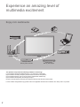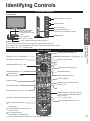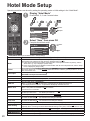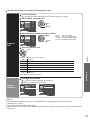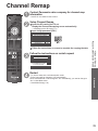
1
Model No.
TH-32LRU5
TH-37LRU5
TH-42LRU5
Installer’s Manual
Hospitality LCD HDTV
English
Thank you for purchasing this Panasonic product.
Please read these instructions before operating your set
and retain them for future reference. The images shown in
this manual are for illustrative purposes only.
TQB2AA0656F
Experience an amazing level of
multimedia excitement
Enjoy rich multimedia
SD memory card
Camcorder
VCR
Personal computer
Cable box
Amplifier with
Speaker system
DVD Recorder/
Blu-ray Disc recorder
DVD Player/
Blu-ray Disc player
This product incorporates the following software or technology:
(1) the software developed independently by or for Panasonic Corporation,
(2) the software owned by third party and licensed to Panasonic Corporation,
(3) the software based in part on the work of the Independent JPEG Group,
(4) the software developed by the FreeType Project.
(5) open sourced software other than the software licensed under the GPL and the LGPL.
For the software categorized as (5), please refer to the applicable license terms included in the “Setup” menu on product.
2
HDMI, the HDMI logo and HighDefinition Multimedia Interface are
trademarks or registered trademarks
of HDMI Licensing LLC in the United
States and other countries.
Contents
SDXC Logo is a trademark of SD3C, LLC.
Manufactured under license from Dolby Laboratories.
Dolby and the double-D symbol are trademarks of Dolby
Laboratories.
Pro: Idiom is a trademark of Zenith
Corporation.
Please read before using the unit
● Safety Precautions ········································· 4
Quick Start Guide
● Accessories/Optional Accessory ···················· 7
● Connections ················································· 10
● Identifying Controls ······································ 13
Quick Start
Guide
This product qualifies for ENERGY
STAR in the factory default setting
and this is the setting in which
energy savings will be achieved.
Any modifications to the factory
default setting or other factory
default settings could result in
greater energy consumption beyond
levels that meet ENERGY STAR
qualifications.
Enjoy your TV!
Basic Features
TV operation ················································ 14
Watching Videos and DVDs ························· 15
Displaying PC screen on TV ························ 16
Viewing from an SD card ····························· 17
Viewing
●
●
●
●
Advanced Features
Hotel Mode setup ········································· 20
How to Use Menu Functions ························ 21
VIERA LinkTM “HDAVI ControlTM” ·················· 24
Lock ····························································· 28
Editing and Setting Channels ······················· 30
Closed Caption ············································ 32
Input Labels ················································· 33
Guest Menu ················································· 34
Signage Mode ·············································· 35
Loading Welcome Image ····························· 36
Local Authentication Mode ··························· 38
Channel Remap ··········································· 39
Clone the TV setting (SD Clone) ·················· 40
Advanced
●
●
●
●
●
●
●
●
●
●
●
●
●
Support Information
Ratings List for Lock ···································· 41
Technical Information ··································· 42
Troubleshooting ··········································· 46
Care and Cleaning ······································· 48
Specifications ··············································· 49
Support
Information
●
●
●
●
●
3
Safety Precautions
CAUTION
RISK OF ELECTRIC SHOCK
DO NOT OPEN
WARNING: To reduce the risk of electric shock, do not remove cover or back.
No user-serviceable parts inside. Refer servicing to qualified service personnel.
The lightning flash with arrowhead
within a triangle is intended to tell the
user that parts inside the product are a
risk of electric shock to persons.
The exclamation point within a
triangle is intended to tell the
user that important operating and
servicing instructions are in the
papers with the appliance.
Note to CATV System Installer
This reminder is provided to direct the CATV system installer’s attention to Article 820-40 of the NEC that provides guidelines for
proper grounding and, in particular, specifies that the cable ground shall be connected to the grounding system of the building, as
close to the point of cable entry as practical.
Secure Ventilation
Slots and openings in the cabinet and the back or bottom are provided for ventilation, and to ensure reliable operation of the LCD
TV and to protect it from overheating. These openings must not be blocked or covered. There should be at least 4 inches (10 cm)
of space around the TV. The openings should never be blocked by placing the LCD TV on a bed, sofa, rug or other similar
surface. This LCD TV should not be placed in a built-in installation such as a bookcase unless proper ventilation is provided.
Important Safety Instructions
1)
2)
3)
4)
5)
6)
7)
8)
9)
10)
11)
12)
13)
14)
15)
16)
17)
18)
4
Read these instructions.
Keep these instructions.
Heed all warnings.
Follow all instructions.
Do not use this apparatus near water.
Clean only with dry cloth.
Do not block any ventilation openings. Install in accordance with the manufacturer’s instructions.
Do not install near any heat sources such as radiators, heat registers, stoves or other apparatus (including amplifiers) that
produce heat.
Do not defeat the safety purpose of the polarized or grounding-type plug. A polarized plug has two blades with one wider
than the other. A grounding type plug has two blades and a third grounding prong. The wide blade or the third prong are
provided for your safety. If the provided plug does not fit into your outlet, consult an electrician for replacement of the
obsolete outlet.
Protect the power cord from being walked on or pinched particularly at plugs, convenience receptacles, and
the point where they exit from the apparatus.
Only use attachments / accessories specified by the manufacturer.
Use only with the cart, stand, tripod, bracket or table specified by the manufacturer, or sold with the
apparatus. When a cart is used, use caution when moving the cart / apparatus combination to avoid injury
from tip-over.
Unplug this apparatus during lightning storms or when unused for long periods of time.
Refer all servicing to qualified service personnel. Servicing is required when the apparatus has been damaged in any
way, such as power-supply cord or plug is damaged, liquid has been spilled or objects have fallen into the apparatus, the
apparatus has been exposed to rain or moisture, does not operate normally, or has been dropped.
Operate only from the type of power source indicated on the marking label. If you are not sure of the type of power supplied
to your home consult your television dealer or local power
EXAMPLE OF ANTENNA
company.
GROUNDING AS PER
Follow all warnings and instructions marked on the LCD TV.
(NEC) NATIONAL
Never push objects of any kind into this LCD TV through cabinet
ANTENNA
ELECTRICAL
slots as they may touch dangerous voltage points or short out
LEAD-IN WIRE
CODE
parts that could result in a fire or electric shock. Never spill liquid
GROUND CLAMP
of any kind on the LCD TV.
ANTENNA
If an outside antenna is connected to the television equipment,
DISCHARGE UNIT
be sure the antenna system is grounded so as to provide some
ELECTRIC
(NEC SECTION 810-20)
SERVICE
protection against voltage surges and built up static charges.
GROUNDING
EQUIPMENT
In the U.S. Section 810-21 of the National Electrical Code
CONDUCTORS
provides information with respect to proper grounding of the mast
(NEC SECTION 810-21)
and supporting structure, grounding of the lead-in wire to an
GROUND CLAMPS
antenna discharge unit, size of grounding conductors, location of
POWER SERVICE GROUNDING
antenna discharge unit, connection to grounding electrodes, and
ELECTRODE SYSTEM
requirements for the grounding electrode.
(NEC ART 250, PART H)
19) An outside antenna system should not be located in the vicinity of overhead power lines, other electric light, power circuits,
or where it can fall into such power lines or circuits. When installing an outside antenna system, extreme care should be
taken to keep from touching such power lines or circuits as contact with them might be fatal.
20) Unplug this LCD TV from the wall outlet and refer servicing to qualified service personnel under the following conditions:
a.
When the power cord or plug is damaged or frayed.
b.
If liquid has been spilled into the LCD TV.
c.
If the LCD TV has been exposed to rain or water.
d.
If the LCD TV does not operate normally by following the operating instructions.
Adjust only those controls that are covered by the operating instructions as improper adjustment of other
controls may result in damage and will often require extensive work by a qualified technician to restore the
LCD TV to normal operation.
e.
If the LCD TV has been dropped or the cabinet has been damaged.
f.
When the LCD TV exhibits a distinct change in performance - this indicates a need for service.
21) When replacement parts are required, be sure the service technician uses replacement parts specified by the manufacturer that
have the same characteristics as the original parts. Unauthorized substitutions may result in fire, electric shock, or other hazards.
22) WARNING: TO REDUCE THE RISK OF FIRE OR ELECTRIC SHOCK, DO NOT EXPOSE THIS APPARATUS TO RAIN,
MOISTURE, DRIPPING OR SPLASHING.
DO NOT PLACE LIQUID CONTAINERS (FLOWER VASES, CUPS, COSMETICS, ETC.) ABOVE THE SET
(INCLUDING ON SHELVES ABOVE, ETC.).
23) WARNING: SMALL PARTS CAN PRESENT CHOKING HAZARD IF ACCIDENTALLY SWALLOWED. KEEP SMALL
PARTS AWAY FROM YOUNG CHILDREN.
DISCARD UNNEEDED SMALL PARTS AND OTHER OBJECTS, INCLUDING PACKAGING MATERIALS
AND PLASTIC BAGS/SHEETS TO PREVENT THEM FROM BEING PLAYED WITH BY YOUNG CHILDREN,
CREATING THE POTENTIAL RISK OF SUFFOCATION.
24) WARNING: To prevent the spread of fire, keep candles or other open flames away from this product at all times.
25) CAUTION: The Power switch on this unit will not completely shut off all power from AC outlet. Since the power
cord serves as the main disconnect device for the unit, you will need to unplug it from the AC outlet
to shut down all power.
Therefore, make sure the unit has been installed so that the power cord can be easily unplugged
from AC outlet in case of an accident. To avoid fire hazard, the power cord should also be unplugged from the
AC outlet when left unused for a long period of time (for example, when on vacation).
26) CAUTION: TO PREVENT ELECTRIC SHOCK, DO NOT USE THIS PLUG WITH A RECEPTACLE OR OTHER OUTLET
UNLESS THE BLADES CAN BE FULLY INSERTED TO PREVENT BLADE EXPOSURE.
27) CAUTION: USE WITH OTHER STAND MAY RESULT IN INSTABILITY POSSIBLY CAUSING INJURY.
28) CAUTION: DANGER OF EXPLOSION IF BATTERY IS INCORRECTLY REPLACED. REPLACE ONLY WITH THE SAME
OR EQUIVALENT TYPE.
29) CAUTION: This LCD TV is for use only with the following optional accessory. Use with any other type of optional
accessories may cause instability which could result in the possibility of injury.
(All of the following accessories are manufactured by Panasonic Corporation)
• Wall-hanging bracket: TY-WK3L2RW
Always be sure to ask a qualified technician to carry out set-up.
NOTE: This equipment is designed to operate in North America and other countries where the broadcasting system and AC
house current are exactly the same as in North America.
FCC STATEMENT
This equipment has been tested and found to comply with the limits for a Class B digital device, pursuant to Part 15 of the FCC
Rules. These limits are designed to provide reasonable protection against harmful interference in a residential installation.
This equipment generates, uses and can radiate radio frequency energy and, if not installed and used in accordance with the
instructions, may cause harmful interference to radio communications. However, there is no guarantee that interference will not occur
in a particular installation. If this equipment does cause harmful interference to radio or television reception, which can be determined
by turning the equipment off and on, the user is encouraged to try to correct the interference by one or more of the following
measures:
• Reorient or relocate the receiving antenna.
• Increase the separation between the equipment and receiver.
• Connect the equipment into an outlet on a circuit different from that to which the receiver is connected.
• Consult the dealer or an experienced radio/TV technician for help.
This device complies with Part 15 of the FCC Rules. Operation is subject to the following two conditions: (1) This device may
not cause harmful interference, and (2) this device must accept any interference received, including interference that may cause
undesired operation.
FCC Caution:
To assure continued compliance, follow the attached installation instructions and use only shielded interface cables
when connecting to computer or peripheral devices. Any changes or modifications not expressly approved by
Panasonic Corp. of North America could void the user’s authority to operate this device.
FCC Declaration of Conformity
Model No. TH-32LRU5, TH-37LRU5, TH-42LRU5
Responsible Party:
Contact Source:
Panasonic Corporation of North America
Three Panasonic Way, 2F-5, Secaucus, NJ 07094
Panasonic System Communications Company of North America
1-800-973-4390
5
Safety Precautions (Continued)
CEA CHILD SAFETY NOTICES: Flat panel displays are not always supported on the proper stands or
installed according to the manufacturer’s recommendations. Flat panel displays that are inappropriately
situated on dressers, bookcases, shelves, desks, speakers, chests or carts may fall over and may cause
personal injury or even death.
The consumer electronics industry (of which Panasonic is a member) is committed to making home
entertainment enjoyable and safe. To prevent personal injury or death, be sure to follow the following safety
guidelines:
TUNE INTO SAFETY:
•
One size does NOT fit all. Follow the manufacturer’s recommendations for the safe installation and use
of your flat panel display.
•
Carefully read and understand all enclosed instructions for proper use of this product.
•
Don’t allow children to climb on or play with furniture and television sets.
•
Don’t place flat panel displays on furniture that can easily be used as steps, such as a chest of drawers.
•
Remember that children can become excited while watching a program, especially on “larger than life”
flat panel displays. Care should be taken to install the display where it cannot be pushed, pulled over,
or knocked down.
•
Care should be taken to route all cords and cables connected to the flat panel display so that they
cannot be pulled or grabbed by curious children.
WALL MOUNTING: IF YOU DECIDE TO WALL MOUNT YOUR FLAT PANEL DISPLAY, ALWAYS:
•
Use a mount that has been recommended by the display manufacturer and/or listed by an independent
laboratory (such as UL, CSA, ETL).
•
Follow all instructions supplied by the display and wall mount manufacturers.
•
If you have any doubts about your ability to safely install your flat panel display, contact your retailer
about professional installation.
•
Make sure the wall where you are mounting the display is appropriate. Some wall mounts are not
designed to be mounted to walls with steel studs or old cinder block construction. If you are unsure,
contact a professional installer.
•
A minimum of two people are required for installation. Flat panel displays can be heavy.
The American Academy of Pediatrics discourages media viewing for children younger than two
years. For more details, see www.aap.org.
6
Accessories/Optional Accessory
Accessories
Check you have all the items shown.
Accessories
Remote Control
Transmitter
Batteries for the
Remote Control
Transmitter (2)
N2QAYB000485
Pedestal
AA Battery
Operating Instructions
Wall-hanging bracket
TY-WK3L2RW
Please contact your nearest Panasonic dealer to purchase the recommended
wall-hanging bracket. For additional details, please refer to the wall-hanging
bracket installation manual.
Screw for fixing the TV onto the
wall-hanging bracket
(not supplied with the TV)
Back of the TV
7.9 ”
(200 mm)
Depth of screw:
Minimum: 0.39” (10.0 mm)
Maximum: 0.47” (12.0 mm)(32”/37”)
1.57” (40.0 mm) (42”)
7.9 ”
(200 mm)
M6
Holes for wall-hanging bracket
installation
WARNING
(View from the side)
Customer assumes liability if mounting the unit themselves or if a Panasonic bracket is not used. Any damage resulting
from not having a professional installer mount your unit will void your warranty.
Always be sure to ask a qualified technician to perform any necessary set-up. Incorrect fitting may cause equipment to
fall, resulting in injury and product damage.
Do not mount the unit directly below ceiling lights (such as spotlights, floodlights or halogen lights) which typically give off
high heat. Doing so may warp or damage plastic cabinet parts.
Take care when fixing wall brackets to the wall. Always ensure that there are no electrical cables or pipes in the wall
before hanging bracket.
When using an angled-type wall hanging bracket, please ensure that there is sufficient space for the connecting cables
so that they do not press against the wall when the TV is tilted forward.
For safety reasons, remove units no longer being used from their wall-mounted locations.
Accessories/Optional Accessory
Optional Accessory
Quick Start
Guide
How to assemble (p. 8)
Installing the remote’s batteries
Open
Close
Hook
Note the correct polarity
(+ or -).
Caution
Incorrect installation may cause
battery leakage and corrosion,
resulting in damage to the remote
control.
not mix old and new batteries.
• Do
not mix different battery types (such
• Do
as alkaline and manganese batteries).
not use rechargeable (Ni-Cd)
• Do
batteries.
Do not burn or break batteries.
7
Accessories/Optional Accessory
(Continued)
Attaching the pedestal to TV
■Assembling the pedestal
Fix securely with assembly screws A . (Total 4 screws)
Tighten screws firmly.
Accessories
Assembly screws
A Screws (4)
A
Bracket
XSS4+16FJK
size (M4 × 16)
Front
B Security screw (1)
THE2AC004J
size (M4 × 12)
■Set-up
Base
C Screws (4)
XYN4+F12FJK
size (M4 × 12)
Fix securely with assembly screws C . (Total 4 screws)
B is used as security screw if necessary.
Tighten screws firmly.
B and C
Bracket (1)
TBL4GA3014 (TH-32LRU5)
TBL2AA3005 (TH-37LRU5)
TBL2AA3006 (TH-42LRU5)
B and C
Foam mat or
thick soft cloth
Base (1)
WARNING
Do not disassemble or modify the pedestal.
Otherwise the TV may fall over and become damaged, and personal injury may result.
TBL2AX00501A (TH-32LRU5)
TBL2AX00511 (TH-37LRU5)
TBL2AX00521 (TH-42LRU5)
Caution
Do not use any other TV and displays.
Otherwise the TV may fall over and become damaged, and personal injury may
result.
Do not use the pedestal if it becomes warped or physically damaged.
If you use the pedestal when it is physically damaged, personal injury may result. Contact your nearest Panasonic
Dealer immediately.
During set-up, make sure that all screws are securely tightened.
If sufficient care is not taken to ensure screws are properly tightened during assembly, the pedestal will not be strong
enough to support the TV, and it might fall over and become damaged, and personal injury may result.
Reference of connection
Antenna terminal
Pin terminals
HDMI terminal
red blue green
green
Firmly tighten by hand.
8
Match colors of plugs and terminals.
Insert firmly.
Insert firmly.
Location
Place the TV at a comfortable distance for viewing. Avoid placing it where sunlight or other bright light (including reflections)
will fall on the screen. Use of some types of fluorescent lighting can reduce remote control transmitter range. Adequate
ventilation is essential to prevent an internal component failure. Keep away from areas of excessive heat or moisture.
■Adjust the stand to your desired angle.
The stand angle can be rotate 30°/60°/90° to the right/left. (see Control rotation angle)
[Rotation angle: 60°]
[Rotation angle: 90°]
TH-32LRU5
TH-37LRU5
TH-42LRU5
a: 9.8 ” (248 mm)
b: 7.6 ” (193 mm)
a: 11.0 ” (279 mm)
b: 8.8 ” (222 mm)
a: 12.5 ” (316 mm)
b: 9.8 ” (248 mm)
TH-32LRU5
TH-37LRU5
TH-42LRU5
The rotation angle can be controlled at 30° or 60°.
It is not necessary to attach the screws for the 90° angle rotation.
Temporarily remove the 5 screws shown below.
Attach A screws (2) to each angle control position.
[Bottom view]
[Front of swivel plate]
[Back of swivel plate]
TH-32LRU5
TH-37LRU5
TH-42LRU5
a: 17.3 ” (439 mm)
b: 14.2 ” (360 mm)
a: 19.7 ” (500 mm)
b: 16.4 ” (416 mm)
a: 21.9 ” (555 mm)
b: 18.4 ” (467 mm)
Accessories
A Screws (2)
XSN3+4FJ
size (M3 × 4)
[For 30°]
2
1
B Security screw (2)
THM2AB001
C Wood screws (4)
XTS5+20AFJK
Swivel plate
5
3
■Set-up
4
Screw the wood screws (2) into the positions
a of the table or desk.
Note
Use C wood screws for fixing the pedestal.
(Total 4 screws)
B is used as security screw if necessary.
Accessories/Optional Accessory
■Control rotation angle
a: 15.0 ” (381 mm)
b: 12.8 ” (323 mm)
a: 17.1 ” (433 mm)
b: 14.7 ” (373 mm)
a: 19.0 ” (483 mm)
b: 16.5 ” (418 mm)
Quick Start
Guide
b
b
b
a
a
a
[Rotation angle: 30°]
[For 60°]
Align the swivel hole in the bottom of the
swivel plate with wood screws that was
screwed in previously, and place the TV
set onto the swivel plate.
[Back of fixed plate]
[View from above]
b
Screw the wood screws (2) into the
holes b to fix the pedestal.
6.5” (165 mm)
b
5.7” (144 mm)
0.079” – 0.091”
(2 – 2.3 mm)
6.1” (155 mm)
a
Slide the TV set forwards until it stops,
then fix it in place.
the TV set in a position where it will not protrude from the table when swiveled.
• Place
• Make sure there is enough space between the TV set and wall, so that when the TV set is swiveled it does not hit the wall.
9
Connections
Connection panel
■Side panel
■Back panel
RF connection*
* For more details on the external equipment’s connections, please refer to the operating manuals for the equipment.
10
Connecting Antenna
VHF/UHF Antenna
NTSC (National Television System Committee):
Conventional broadcasting
ATSC (Advanced Television Systems Committee):
Digital TV Standards include digital high-definition television (HDTV), standard-definition television (SDTV), data
broadcasting, multichannel surround-sound audio and interactive television.
•
•
AC 110-127 V
60 Hz
VHF/UHF Antenna
Cable TV
Quick Start
Guide
Power Cord
(Connect after all the
other connections.)
or
Back of the TV
•
•
•
Example of connections
Connections
Cable
You need to subscribe to a cable TV service to enjoy viewing their programming.
You can enjoy high-definition programming by subscribing to a high-definition cable service.
The connection for high-definition can be done with the use of HDMI or Component Video cable. (see below)
To view high-definition programming, select the correct video input. (p. 15)
To use HDMI terminals
Side panel
Back panel
AV Equipment
HDMI
AV OUT
HDMI cable
e.g. Blu-ray Disc
player
Connecting to the HDMI terminals will enable you to enjoy high-definition digital images and high-quality sound.
The HDMI connection is required for a 1080p signal.
VIERA Link connection, please refer to p. 25
To use COMPONENT terminals
Y
green
green green
blue
blue blue
red
white
red
PB COMPONENT
VIDEO OUT
PR
red
red
L
AUDIO
R OUT
white white
red
AV Equipment
e.g. Blu-ray Disc
player
red
Note
Not all cables and external equipment shown in this book are supplied with the TV.
For more details on the external equipment’s connections, please refer to the operating manual for the equipment.
11
Connections (Continued)
Example of connections
To use COMPOSITE terminals
AV Equipment
yellow
yellow yellow
white
white white
L
COMPOSITE
OUT
e.g. DVD Recorder
or
R
red
red
red
e.g. VCR
To use AUDIO OUT terminals
Audio equipment
AUDIO IN
Audio cable
Connect a cable which matches
the audio in terminal on the unit.
To use MTI terminal
External TA
MTI OUT
Cross Cable
Terminal adapter
To use PC terminal
Connect a cable which matches
the audio out terminal on the PC.
Audio cable
PC
AUDIO OUT
PC OUT
RGB PC cable
Conversion adapter
(if necessary)
Note
Not all cables and external equipment shown in this book are supplied with the TV.
For more details on the external equipment’s connections, please refer to the operating manual for the equipment.
12
Identifying Controls
TV controls/indicators
Front of the TV
Selects channels in sequence
Volume up/down
Menu navigations
POWER button
Power indicator
(on: red, off: no light)
C.A.T.S. (Contrast Automatic Tracking System)
Remote control
Closed Caption On/Off (p. 14)
Switches TV On or Off (Standby)
Selects Audio Mode for TV viewing (p. 14)
Changes the input mode (p. 15)
Exits from menu screen
∗
Displays Main Menu (p. 21, 34)
∗
Identifying Controls
Connections
Note
The TV consumes a small amount of electric energy even when turned off.
Do not place any objects between the TV remote control sensor and remote control.
Do not place C.A.T.S. in a blocked area.
Quick Start
Guide
Changes the input mode
Chooses menu and submenu entries
Remote control sensor
within about 23 feet
(7 meters) in front of the
TV set
Viewing from SD Card (p. 17)
Displays Sub Menu (p. 18)
Selects/OK/Change
Colored buttons
(used for various functions)
Returns to previous menu
Channel up/down
Volume up/down
Sound mute On/Off
Displays or removes the channel
banner (p. 14)
∗
Changes aspect ratio (p. 14, 42)
Switches to previously viewed channel
Use for SD mode operation
∗ : Disable keys
: Not possible when connected to TA
(Online mode)
: For setup mode only
Not available in Hotel Mode On.
For other Remote control, please refer to the operating manual for it.
Numeric keypad to select any channel
(p. 14) or press to enter alphanumeric
input in menus
(p. 15, 16, 28, 30, 33)
Use for digital channels. (p. 14)
13
TV operation
Connections (p. 10-12)
Turn the TV On with the POWER button
(Remote)
(TV)
Input select: press
(p. 15)
or
or
Select a channel number
To directly enter the digital
channel number
(Remote)
up
When tuning to a digital channel,
press the button to enter the
minor number in a compound
channel number.
or
down
(TV)
example: CH15-1:
Note
Reselect “Cable” or “Antenna” in “ANT in” of “ANT/Cable setup” to switch the signal
reception between cable TV and antenna. (p. 31)
The channel number and volume level remain the same even after the TV is turned
off.
Other Useful Functions (Operate after
)
Select Audio mode for watching TV
Listen
with SAP
(Secondary
Audio
Program)
Digital mode
Press SAP to select next audio track (if available) when receiving a digital channel.
Audio track 1 of 2
English (Main Audio)
English audio
Analog mode
Press SAP to select the desired audio mode.
• Each press of SAP will change the audio mode. (Stereo/SAP/Mono)
Switches the Closed caption mode On or Off
Closed
caption
Closed caption Off
Closed caption On
Closed caption On mute
Displays or removes the channel banner
Information
recall
15-2
ABC-HD
Station
identifier
Change
aspect
ratio
14
Sleep timer
remaining time
Channel
30
CC
SAP
TV-G 1080i 4:3
Closed SAP
Rating Signal Aspect ratio
caption indication level resolution
Press FORMAT to cycle through the aspect modes (p. 42)
• 480i, 480p: FULL/JUST/4:3/ZOOM
• 1080p, 1080i, 720p: FULL/H-FILL/JUST/4:3/ZOOM
Watching Videos and DVDs
If you have applicable equipment connected to the TV, you can watch videos and DVDs on the TV screen.
Input Select
You can select the external equipment to access.
With the connected equipment turned On
Display the Input select menu
Select the input mode
Press the corresponding NUMBER
button on the remote control to
select the input of your choice.
Input select
1
TV
2
HDMI 1
3
HDMI 2
4
Component
5
Video
6
PC
DVD
AUX
or
select
(example)
HDMI 1
DVD
Terminal
Label
(example)
During the selection, if no action
is taken for several seconds, the
“Input select” menu disappears.
The terminal and label of the
connected equipment are
displayed.
To label each of the inputs,
please refer to p. 33.
Operate the connected equipment using the remote
control supplied with the equipment
Note
For details, see the manual for the connected equipment.
Watching Videos and DVDs
TV operation
Note
The input label will be displayed on the “Input select” screen if the Input label is set
on p. 33.
For more details on “Input labels”, refer to p. 33.
Viewing
enter
Select the input of your choice,
then press OK.
To return to TV
15
Displaying PC Screen on TV
The screen of the PC connected to the unit can be displayed on the TV.
You can also listen to PC sound with the audio cable connected. To connect PC (p. 12)
Display the Input select menu
Input select
1
TV
2
HDMI 1
3
HDMI 2
4
Component
5
Video
6
PC
DVD
AUX
(example)
Select “PC”
Corresponding signals
(p. 45)
PC
Displays
PC screen
To return to TV
PC menu setting (change as desired)
Making settings
Menu
“How to Use Menu Functions”
Item
Reset to defaults
Sync
Dot clock
H-position
Picture
PC
adjustments
V-position
Clock phase
/
to
(p. 21)
Adjustments/Configurations (options)
Resets PC adjustments. Confirmation screen is displayed. Select “Yes” and press OK to reset.
H & V:
The H and V sync signals are input from the HD/VD connector. (p. 45)
On green: Uses a synchronized signal on the Video G signal, which is input from the
G connector. (p. 45)
Alleviates the problem if a picture appears to be vertically-striped, flickers partially or is blurred.
Adjusts the horizontal position.
Adjusts the vertical position.
Alleviates the problem if the whole picture appears to flicker or is blurred.
First adjust the Dot Clock to get the best possible picture, then adjust the
Clock Phase so that a clear picture appears.
Note
It may not be possible to display a clear picture due to poor input signals.
Input
resolution
H-frequency
V-frequency
16
Audio menu (p. 22-23)
Switches to wide display.
Input signal switched from 640×480 to 852×480
Input signal switched from 1024×768 to 1280×768 or 1366×768
Displays the H (Horizontal)/V (Vertical) frequencies.
Display range
Horizontal: 15 - 110 kHz
Vertical:
48 - 120 Hz
Viewing from an SD card
This function that lets you easily view still images on a television by simply inserting an SD card into the SD card slot.
(Media other than SD Cards will not work.)
Insert the SD card
Insert the card
Gently insert the SD Card label surface facing front.
Remove the card
Label surface
Push until a
click is heard
Press in lightly
on SD Card,
then release.
Cutout
Compliant card type (maximum capacity): SDXC Card (64 GB), SDHC Card (32
GB), microSDHC Card (16 GB), SD Card (2 GB), miniSD Card (2 GB), microSD
Card (2 GB) (requiring microSDHC Card/miniSD Card/microSD Card adapter)
If a microSDHC Card, miniSD Card or microSD Card is used, insert / remove it
together with the adapter.
For cautions and details on SD Cards (p. 43)
Manual operation (“Image viewer auto play” is “Off”)
Display “IMAGE VIEWER” (Thumbnail)
Viewing
Select the data to be viewed
Error display (titles that could not be loaded, etc.)
IMAGE VIEWER
select
All photos
To display/hide the Information area
Select
SUB MENU
1/48
File name:
p1010001.JPG
Date:
23/10/2009
Size:
1600X1200
SD memory card
OK
RETURN
file number / total file number
Note
Depending on the JPEG format, “Information” contents may not be displayed
correctly. Refer to p. 43 (Data format for SD card browsing) for details.
View
Photo status
Slideshow
Single view
Single view
Viewing from an SD card
Displaying PC Screen on TV
view
Navigation Guide
Slideshow
Press to exit from
a menu screen
Rotate
Prev.
Rotate
Prev.
Stop
Press to return to
the previous screen
Single view
Next
RETURN
Stop
Displays one at a time
Next
RETURN
Prev.
Stop
Next
RETURN
Rotate 90 degrees (counter-clockwise)
To next photo
Stop
To previous photo
To display/hide the Navigation Guide
Return to the Thumbnail view
17
Viewing from an SD card (Continued)
Display the SUB MENU
Note
This operation is disabled when “Mode” in Hotel Mode menu is set to “On”.
Display “Setup SUB MENU” and select item
select
SUB
MENU
Setup SUB MENU
Slideshow settings
Thumbnails size
OK
Slideshow settings (see below)
Thumbnails size
To change the number of photos on a thumbnail screen
at a time
(7 × 4 ⇔ 10 × 6)
Slideshow
Adjust items
select
Slideshow settings
Frame
Off
Photo effect
Off
Transition effect
Photo size
Off
OK
Normal
Burst playback
Off
Display interval
Normal
Repeat playback
On
● To stop in mid-cycle
Soundtrack settings
Slideshow settings
Settings
Frame
Photo effect
Transition effect
Photo size
Burst playback
Display interval
Item Description
Select the Frame (Off/Array/Collage/Drift(with calendar)/Drift/Gallery(with calendar)/Gallery/Cinema)
Select the display effect (Off/Sepia/Gray scale)
Select the Transition effect shown between photos (Off /Fade in/Wipe ↓/Wipe ↑/Wipe →/Wipe ←/
Slide in ↓/Slide in ↑/Slide in →/Slide in ←/Zoom in/Comb ↑↓/Comb →←/Dissolve/Checker
wipe/Motion/Random)
Removes the black borders that are added according to the size of the photo being displayed. (Normal/Zoom)
Continuously plays photos that were shot. (On/Off)
Set “Display interval” each image is displayed in the Slideshow mode.
(Short/Fast/Normal/Slow/Very slow)
Turn the Slideshow Repeat (cycle) function on or off (Off/On).
Repeat playback
Soundtrack
Select the music (Off/Music 1/Music 2/Music 3)
settings
• Picture quality may become lower depending on the slideshow settings.
• Picture setting may not work depending on the slideshow settings.
Soundtrack settings
Select “Soundtrack
settings”
Soundtrack settings
Slideshow settings
Frame
Off
Off
Photo effect
Off
Music 1
Transition effect
Off
Music 2
Photo size
Normal
Burst playback
Off
Display interval
Normal
Repeat playback
On
Soundtrack settings
18
Select the music
Music 3
Music 1
select
OK
Other settings in IMAGE VIEWER
Note
This operation is disabled when “Mode” in Hotel Mode
menu is set to “On”.
Display “Menu”
Picture
Picture
1/2
Reset to defaults
Vivid
Picture mode
Back light
select
adjust
+20
Contrast
0
Brightness
0
Color
0
Tint
0
Sharpness
0
example: Picture menu
Picture menu/Audio menu
(p. 22-23)
Select the item
Menu
Adjust the Picture and Audio
select
Audio
OK
Set
Viewing
Viewing from an SD card
19
Hotel Mode Setup
Operating restrictions can be set by setting the operating mode or initial settings in the “Hotel Mode”.
Display “Hotel Mode”
Press MENU, G, Y and 0 remote button.
1/3
Hotel Mode
Save
select
Adjust
On
Mode
TA Ctrl
External
Initial input
HDMI 1
Initial channel
101-1
Select “Save” then press OK
Complete Hotel Mode setup
1/3
Hotel Mode
select
Save
On
Mode
TA Ctrl
External
Initial input
HDMI 1
ok
Hotel Mode menu (An underlined item is default setting)
Item
Mode
TA Ctrl
Initial input
Initial channel
Initial volume
Max. volume
OSD Ctrl
Button lock
Power ctrl
Adjustments/Configurations (alternatives)
Sets operation mode Hotel mode(Guest mode) or Setup mode. (Off/On)
These settings are enabled even after the AC is switched off and on again.
On: These menu restrictions are enabled. Communication can be performed with TA (Online), and the
“Guest menu” (p. 34) is displayed. (Guest mode)
Off: These menu restrictions are disabled. Communication with TA cannot be performed, and the “Setup
menu” is displayed. (Setup mode)
Sets TA (Terminal Adaptor) status. (External/Local Auth/Off)
External: Use External TA Local Auth: Local Authentication Mode is enabled by special procedure so it is not
visible in the default menu
Selects Input when the TV is turned on.
Does not operate when input from TA* to the TV is prohibited.
(-/RF/HDMI 1-2/Component/Video/PC/SD)
Sets the channel at power-on.
Sets the volume level at power-on. (0-100)
Does not operate when control from TA to the TV is prohibited.
Sets the maximum volume level. (0-100)
Limits the OSD display. (Off/Pattern1)
Pattern 1: “Recall” and “Shut-off notification” messages are not displayed at power-on.
Also displayed when “Pattern 1” is specified as the display command from TA.
Limits the TV panel button operation. (Off/All/Pattern1)
Pattern 1: Only INPUT and POWER buttons are available.
All: All buttons are not available.
Sets the screen condition when the AC power is switched on. (Off/On)
Off: Starts up in last screen.
On: Starts up in screen On.
Remote
Switches Operation guide according to remote control. (Panasonic/Others)
Sets CC setting status. (On/Off)
CC reset
Off: Saves the last settings. On: Resets all CC settings to defaults.
Sets Lock setting status. (Off/On)
Lock reset
Off: Saves the last settings. On: Resets all Lock settings to defaults.
Select CC standard to be prioritized (EIA-708 or EIA-608). (708/608) (p. 42)
CC Priority
On: Hides warning panel of communication error when connecting with STB etc. (Off/On)
Com warning
(Especially when connecting with GuestTek/nSTREAM Analog VOD system, switches this menu to “On” .)
Sets Welcome Image status. (3sec/5sec/7sec/Off/Load Image)
Loading Welcome Image (p. 36)
Welcome Image
On: When using input switching commands with RS232 connection while connected to STB, switch Menu to “On”. (Off/On)
CP Mode
HDMI Audio Sync Switch to Mode 2 if experiencing problem with HDMI audio. (Mode1/Mode2)
Switch to Mode 2 if experiencing problem with RF picture and audio. (Mode1/Mode2)
Decode mode
20
* TA: Terminal Adapter
How to Use Menu Functions
Various menus allow you to make settings for the picture, sound, and other functions so that you can enjoy
watching TV best suited for you.
Guest menu (p. 34)
Display the menu
Shows the functions that can be adjusted.
Some functions will be disabled depending on
the type of input signal.
Menu structure
Menu
Menu bar
Press OK to move to the Menu items.
Input labels
HDMI 1
Component
Video
PC
Select or enter the name of the device
connected to the HDMI 1 terminal.
Select
Change
Operation guide
RETURN
R Customize label G
Help information
B
Y
(example: Input labels)
Select the menu
Menu
Picture
1/2
Reset to defaults
Picture mode
Back light
select
How to Use Menu Functions
Hotel Mode Setup
Menu items
Press OK to proceed to next screen if
available.
HDMI 2
Custom
+20
next
0
Contrast
Select the item
Picture
1/2
select
Reset to defaults
Picture mode
Back light
Press to exit from
a menu screen
Custom
+20
Contrast
0
Brightness
0
Color
0
Tint
0
Sharpness
0
Advanced
Menu
Resets all picture adjustments to factory
default settings except for “Advanced
picture”.
(example: Picture menu)
Press to return
to the previous
screen
Adjust or select
Menu
Picture
1/2
Reset to defaults
Picture mode
Back light
Vivid
+20
Contrast
0
Brightness
0
Color
0
Tint
0
Sharpness
0
adjust
or
select
Selects from preset picture modes.
(example: Picture menu)
21
How to Use Menu Functions
Menu list
Menu
Item
Reset to defaults*
Resets all picture adjustments to factory default settings except for “Advanced picture”.
Picture mode
Basic picture mode (Vivid/Standard/Cinema/Custom) (p. 44)
Back light
Adjusts the luminance of the back light.
Contrast, Brightness,
Color, Tint, Sharpness
Adjusts color, brightness, etc. for each picture mode to suit your taste
Display range
Contrast/Brightness/Color/Sharpness: 0 - 100
Tint:
-50 - +50
Color temp.
Selects a choice of Cool (blue), Normal, or Warm (red) color. (Cool/Normal/Warm)
Color mgmt.
On: Enhances green and blue color reproduction, especially outdoor scenes. (Off/On)
A.I. picture
Controls dark areas without affecting the black level or brightness in the overall picture
(Off/On)
C.A.T.S.
Adjusts the brightness and gradation according to the ambient lighting condition. (Off/On)
Video NR
Reduces noise, commonly called snow. Leave it off when receiving a strong signal. (Off/On)
•
Aspect adjustments
Picture
Screen format
Changes the format (aspect ratio). (FULL/H-FILL/JUST/4:3/ZOOM)
Lets you choose the aspect depending on the format of received signal. (p. 42)
HD size
Selects between 95 % (Size 1) or 100 % (Size 2) for the scanning area with High-definition
signal. (Size 1/Size 2)
Select “Size 1” if noise is generated on the edges of the screen.
Size 1: Selected item for “HD size”. Scanning 95 %
Size 2: Selected item for “HD size”. Scanning 100 %
H size
Adjusts the horizontal display range to reduce noise of both side edges of an image. (Size 1/Size 2)
Size 2: Adjusts the image size according to the aspect mode for to reduce noise. (p. 42)
PC adjustments
HDMI settings
Advanced picture
Audio
22
Adjustments/Configurations (alternatives)
•
•
Sets PC display (p. 16)
HDMI/DVI
RGB range
Prevents the blown out highlights and blocked up shadows when a wide-range signal is
received. Selects between standard RGB range (16-235 bits) or non-compliance (0-255
bits). (Auto/Standard (16-235)/Nonstandard)
Auto: Switches the RGB range (Standard (16-235)/Nonstandard) depending on the HDMI
signal information.
Contents type
Sets content type to each HDMI input. (Off/Auto/Photo/Graphics)
Auto: Switches content type automatically depending on the HDMI signal information.
Photo: Best setting for JPEG viewing.
Graphics: Best setting for On-Screen display of connected equipment.
3D Y/C filter
Minimizes noise and cross-color in the picture. (Off/On)
Color matrix
Selects image resolution of component-connected devices (SD/HD)
SD: Standard Definition
HD: High Definition
Only used with 480p video signal.
MPEG NR
Reduces noise of specific digital signals of DVD, STB, etc. (Off/On)
Black level
Selects Dark or Light. Valid only for external input signals. (Dark/Light)
3:2 pulldown
Adjusts the picture recorded in 24 fps for optimum quality. (Off/On/Auto)
•
•
Reset to defaults*
Resets Bass, Treble, and Balance adjustments to factory default settings.
Bass
Increases or decreases the bass response.
Treble
Increases or decreases the treble response.
Balance
Emphasizes the left / right speaker volume.
In the AV mode, the Audio and Setup menus give fewer options.
* Confirmation screen is displayed. Select “Yes” and press OK to reset.
(Continued)
Menu list
Menu
Adjustments/Configurations (alternatives)
Volume leveler
Minimizes volume disparity after switching to external inputs.
Surround
HDMI 1 in
HDMI 2 in
Switches to “Off” when using external speakers (Off/On)
“Surround” and “Volume leveler” do not work if “Off” is selected.
The default setting is “Digital” for the HDMI connection. (Digital input signal)
Select audio input terminal when DVI cable is connected. (Analog audio input signal)
(Digital/Component/Video)
DTV language
and SAP settings
Enhances audio response when listening to stereo. (Off/On)
Advanced audio
Audio
Preferred
language
Selected preferred language is used for automatic selection of service. (English/Spanish/
French)
Preferred audio
type
Selected preferred audio type is used for automatic selection of service. (Main Audio/
Hearing Impaired/Visually Impaired)
TV speakers
Sleep
Lock
•
The TV can automatically turn Off at the designated time (0/15/30/60/90)
Locks the programs. (p. 28)
Closed
caption
Closed caption
Displays subtitles (Closed caption). (p. 32)
Language
Selects the screen menu language. (English/Español/Français)
ANT/Cable setup
Sets channels. (p. 30)
Connected
devices
Input labels
Selects the terminal and label of the external equipment (p. 33)
Audio out
To prevent howling, stops output of audio specified in this menu. (p. 33) (On/Off)
VIERA Link settings
Power save
See p. 26-27 for more detail.
Reduces screen brightness to lower power consumption. Eye-friendly for viewing in a dark
room. (Standard/Saving)
To conserve energy, the TV automatically turns off when NO SIGNAL and NO OPERATION
continue for more than 10 minutes. (Stay on/Power TV off)
Note
signal for 10 minutes was activated” will be displayed for about 10 seconds when
• “No
the TV is turned on for the first time after the power was turned off by “No signal for 10
minutes”.
on-screen display will flash 3, 2 and 1 to indicate the last three (3) remaining minutes
• The
prior to the shut-off.
Advanced
ECO/energy saving
Setup
No signal for 10
minutes
How to Use Menu Functions
(picture, sound quality, etc.)
Timer
Item
To conserve energy, the TV automatically turns off when no operation of remote and side
panel key continues for more than 3 hours. (Stay on/Power TV off)
Note
Advanced
setup
No activity for 3
hours
••
•
Image viewer
auto play
Set “Photos” to play back SD cards automatically.
(Photos/Off)
Fast boot
Set “On” to allow for faster booting from standby mode. Note that it consumes more
electricity during the standby mode. (Off/On)
Not in use while “PC” is selected.
“No activity for 3 hours was activated” will be displayed for about 10 seconds when the TV
is turned on for the first time after the power was turned off by “No activity for 3 hours”.
The on-screen display will flash 3, 2 and 1 to indicate the last three (3) remaining minutes
prior to the shut-off.
About
Displays TV version and software license.
Reset to defaults
Performing Reset will clear all items set with Setup, such as channel settings.
23
VIERA LinkTM “HDAVI ControlTM”
Simultaneously control all Panasonic “HDAVI Control” equipped components using one button on the TV remote.
Enjoy additional HDMI Inter-Operability with compatible Panasonic products.
This TV supports “HDAVI Control 5” function.
Connections to equipment (DVD recorder DIGA, HD Camcorder, Home theater system, Amplifier, etc.) with HDMI cables
enables VIERA Link controls.
Equipment with the “HDAVI Control” function enables the following operations:
Version
HDAVI Control or later
HDAVI Control 2 or later
HDAVI Control 3 or later
Operations (See p. 26-27, for more information)
Input Switching
• Automatic
• Power off link
• VIERA Link control only with the TV’s remote control
setting information (Language, time. etc.)
• Provides
• Automatic lip-sync function
HDAVI Control 4 or later
HDAVI Control 5
Return Channel
• Audio
Audio Return Channel (ARC) is a function that enables digital sound signals to
be sent via an HDMI cable back from the TV to a connected audio device.
Note
● Audio return is available only on HDMI1.
■ When adding new equipment, reconnecting equipment or changing the setup after the
connection, turn the equipment on and then switch the TV on. Set the input mode to HDMI1 or
HDMI2 (p. 15), and make sure that the image is displayed correctly.
VIERA Link “HDAVI Control”, is based on the control functions provided by HDMI and industry standard known as HDMI
CEC (Consumer Electronics Control), with unique function that we have developed and added. As such, its operation with
other manufacturers’ equipment that supports HDMI CEC cannot be guaranteed.
Please refer to the individual manuals for other manufacturers’ equipment supporting the VIERA Link function.
■ HDMI cable
This function needs an HDMI compliant (fully wired) cable. Non-HDMI-compliant cables cannot be utilized.
It is recommended that you use Panasonic’s HDMI cable. Recommended part number:
RP-CDHS15 (4.9 ft/1.5 m), RP-CDHS30 (9.8 ft/3.0 m), RP-CDHS50 (16.4 ft/5.0 m)
* For more details on the external equipment’s connections, please refer to the operating manual for the equipment.
24
VIERA Link™ Connections (with VIERA Link function)
■ Terminal overview
Back of the TV
HDMI cable
VIERA LinkTM “HDAVI ControlTM”
■ Connecting DVD Recorder (DIGA)
DVD recorder (DIGA)
with VIERA Link function
■ Connecting Home theater system/AV amp
HDMI 1 is recommended.
HDMI cable
Home theater systems
with VIERA Link function
AV amp with
VIERA Link function
DVD recorder (DIGA)
with VIERA Link function
No optical cable is necessary when connecting a Home Theater
supporting “HDAVI control 5” with an HDMI cable. Audio will be
supported via ARC (Audio Return Channel) (p. 24)
■ Connecting HD Camcorder/Digital camera
Press INPUT and select an available HDMI terminal, then connect the camcorder to this input. After connection,
confirm the HDAVI control functions. (p. 26-27)
Advanced
● One AV amp and one DVD recorder (DIGA) can be operated with this unit.
HDMI / mini HDMI cable
HD Camcorder
with VIERA Link
function
LUMIX with
VIERA Link
function
If connection (or setting) of equipment compatible with HDAVI control is changed, switch the power of this unit Off and
On again while the power of all equipment is On (so that the unit can correctly recognize the connected equipment) and
check that the connected equipment playback operates.
Note
● Individual HDMI equipment may require additional menu settings specific to each model. Please refer to their
respective manuals.
● Some devices use Mini-HDMI terminal. HDMI (type A) to Mini-HDMI (type C) cable or adapter should be used.
25
VIERA LinkTM “HDAVI ControlTM” (Continued)
VIERA Link settings and Available features
To use all VIERA Link functions : After everything is connected, in VIERA Link settings menu, set “VIERA Link” to “On”.
Some features are disabled depending on the “HDAVI Control” version of the equipment.
Please check the list (p. 24)
Display the menu
Select “VIERA Link settings” in “Setup”
Menu
Setup
select
Language
Ant/Cable Setup
Connected devices
VIERA Link settings
next
ECO/energy saving
Advanced setup
About
Reset to defaults
Select “VIERA Link”
Menu
VIERA Link settings
VIERA Link
On
Power off link
Yes
Default speakers
TV
select
Select “On”
Press to exit from
a menu screen
Press to go back
to the previous
screen
26
(default is On)
change
Select and make other settings
Menu
VIERA Link settings
VIERA Link
On
Power off link
Yes
Default speakers
TV
select
Automatic Input Switching
When using a Blu-ray Disc player, DVD player/recorder or Home theater system, the TV will automatically change to
the appropriate input, when playback begins on one of those devices.
• For a Home theater system the speakers automatically switch to the theater system.
Power off link
When “Yes” is selected and the TV is turned off, all connected VIERA Link compatible equipment is also automatically
turned off.
• A Panasonic DVD Recorder will not turn off if it is still in Rec mode.
• The TV remains on even if the VIERA Link compatible equipment is turned off.
Default speakers
“TV” is the default setting. To set the Home theater system as Default speakers, change the Default speakers setting
from “TV” to “Theater”. Sound will be output from the Home theater whenever the TV is powered on.
Automatic lip-sync function
TV provided setting information
The following information about the TV settings can be transmitted to each piece of equipment (Recorder/Home
theater/Player) that has “HDAVI Control 3 or later” function connected to a TV with an HDMI cable.
Recorder
Home theater
Player
On Screen Display Language setting
(English/Español/Français)
Transmittable data
○
○
○
Panel Aspect Ratio
(16:9 fixed)
○
○
○
Closed caption information
(Mode/CC type/Digital setting)
○
---
---
Note
● There is a possibility that all the GUI language information might be set from equipment that has an HDMI CEC
VIERA LinkTM “HDAVI ControlTM”
Minimizes lip-sync delays between the picture and audio when you connect to a Panasonic theater system or
Amplifier.
function connected to the TV with an HDMI cable. Depending on the operating conditions or the specification for
each piece of equipment the setting may or may not be applied.
● For more details on the external equipment’s operation, please refer to the operating manual for the equipment.
Advanced
27
Lock
You can lock specified channels or shows to prevent children from watching objectionable content.
Display the menu
Select “Lock”
Menu
next
Password
Enter password.
- - - -
select
You will be asked to enter your password each time you
display the Lock menu.
Blocks access, with password protection, to
programs.
Input your 4-digit password
A 4-digit code must be entered to view a blocked program or change rating settings.
Menu
Password
Enter password.
* * * -
If it is your first time entering the password, enter the password twice in order to
register it.
Select the Lock mode
Menu
Lock
Mode
On
Program
Off
set
Change password
select
Press to exit from
a menu screen
Caution
Make a note of your
password in case
you forget it. (If you
have forgotten your
password, consult
your local dealer.)
Note
When you select a
locked channel,
a message will be
displayed that allows
you to view the
channel if you input
your password.
28
Off:
On:
Unlocks all the lock settings of “Program”.
Locks all the inputs regardless of the lock settings of “Program”.
Select the item
Menu
Lock
Mode
On
Program
Off
Change password
select
Set
set
To select the channel or the rating of the program to lock
To set a rating level
“V-chip” technology enables restricted shows to lock according to TV ratings.
Select “Mode” and set to “On”
Menu
Program lock
Mode
On
MPAA
Off
U.S.TV
Off
C.E.L.R.
Off
C.F.L.R.
Off
set
select
Select the rating category you wish to follow
Menu
next
Program lock
Mode
On
MPAA
Off
U.S.TV
Off
C.E.L.R.
Off
C.F.L.R.
Off
MPAA:
U.S.TV:
C.E.L.R.:
C.F.L.R.:
U.S. movie ratings
U.S. TV program ratings
Canadian English ratings
Canadian French ratings
select
Program
lock
Select the rating to lock
select
No rating
General Audience: All ages admitted
Parental Guidance Suggested
Parents Strongly Cautioned: Inappropriate for children under 13
Restricted: Under 17 requires accompanying parent or adult guardian
No one 17 and under admitted
Adults only
To get more information (p. 41)
To change the password
In , select “Change password” and press OK
Input the new 4-digit password twice
Change
password
Menu
Menu
Lock
Mode
Off
Program
Off
Change password
Advanced
NR
G
PG
PG-13
R
NC-17
X
Lock
Example of “MPAA” (U.S. movie ratings)
Change password
Enter new password.
- - - -
Note
This television is designed to support the “Downloadable U.S. Region Rating System” when available.
(Available only in U.S.A.)
The Off rating is independent of other ratings.
When placing a lock on a specific-age-based-rating level, the Off rating and any other more restrictive ratings will also
be blocked.
29
Editing and Setting Channels
The current channel settings can be changed according to your needs and reception
conditions.
Display the menu
Auto
program
Set
automatically
Select “Setup”
Menu
Setup
next
Language
Ant/Cable Setup
Connected devices
VIERA Link settings
select
ECO/energy saving
Advanced setup
About
Reset to defaults
Adjusts Surf mode, Language, Clock, Channels,
Inputs, and other settings.
Select “ANT/Cable setup”
Menu
Setup
next
Language
Ant/Cable Setup
Connected devices
VIERA Link settings
select
ECO/energy saving
Advanced setup
Manual
program
Set
manually
About
Reset to defaults
Scans for Antenna or Cable channels.
Specify when using Cable or Satellite box.
Select the function
Menu
ANT/Cable setup
ANT in
Cable
next
Auto program
Manual program
Signal meter
Press to exit from
a menu screen
select
Automatically searches and saves available
channels to memory.
Set
Signal
meter
Check signal
strength
To reset the settings of the Setup menu
Select “Reset to defaults” in the Setup menu ( ) and
press OK
Input your 4-digit password with number buttons
Select “YES” on the confirmation screen and press OK
30
Automatically searches and adds available channels to the memory.
Select “ANT in”
Start scanning the channels
Select “Cable” or “Antenna”
Or select “Not used”.
(Available channels are automatically set.)
Auto program
Select “Auto program”
Menu
Progress
ANT/Cable setup
ANT in
Cable
next
Auto program
10
Number of digital channels
0
Press RETURN to quit
Manual program
Signal meter
select
RETURN
After the scanning is completed, select “Apply”.
(see below ).
All previously saved channels are erased.
Use this procedure when changing the channel setup or
changing the channel display.
Also, use this to add or skip channels from the channel list
manually.
Edit
Edit CH caption
Channel
Apply
Select
Cancel
Caption
...
...
3
...
...
Yes
4
...
...
Yes
5
...
...
Yes
2
Add
Apply
Add
...
3
...
...
Yes
4
...
...
Yes
Yes
...
5
...
Yes
...
Yes
...
Caption
...
8
9
Select
Manual program
Edit
Yes
Add
Yes
RETURN
R Prev.page
Move the cursor to a channel number
next
Yes
6
7
G Next page
B
Y
Y
Delete
Caption
select the item
to edit (Caption/
Add)
Cancel
Caption
...
2
set
G
B
ABC → abc
Select or edit the station identifier.
(maximum 7 characters available)
Add
Press OK to select “Yes (add)” or “No (skip)”
Select the item to edit
Edit
or
RETURN
R
select
next
Yes
Manual program
Channel
change
OK
Manual program
Edit
80-101
@ D---A
Caption
Apply
Channel
• Caption:
Changes the station identifier
• Add:
Adds or skips channels
Cancel
2
Caption
...
...
Add
Yes
3
...
...
Yes
select
Press OK to tune
to the channel.
Select “Apply”
program
Apply
Proceed to
next page
Go back to the previous
page
Caption
...
Cancel
select
Add
...
Yes
OK
To cancel the Edit
Edit
Channel
Changes will be lost. Continue?
Apply
Cancel
2
Caption
...
Add
...
Yes
3
...
...
Yes
4
...
...
Yes
5
...
...
Yes
No
Yes
select
next
Advanced
el
Manual program
Editing and Setting Channels
Caption
Select “Edit”
Channel
8%
Number of analog channels
OK
(returns to “ANT/
Cable setup”)
select “Yes”
Check the signal strength if interference is found or freezing occurs on a digital image.
Menu
Signal meter
If the signal is weak, check the antenna.
-Channel
Tune manually
If no problem is found, consult your local dealer.
Signal strength
Current
86%
Peak level
98%
Selects which channel to be tested for signal
strength.
or
Signal intensity
change
channel
OK
Note
Not available if “Cable” is selected in “ANT in” (see above).
Available only for digital antenna channels.
If “Lock” (p. 28) is activated and “ANT/Cable setup” is selected, “Enter password.” will be displayed.
31
Closed Caption
Display the menu
Select “Closed caption”
Menu
Closed caption
Reset to defaults
Mode
next
On
Analog
CC1
Digital
Primary
select
Digital setting
Press to exit from
a menu screen
Display broadcast TV’s Closed Caption (CC)
text when available.
The television includes a built-in decoder that is capable of providing a text display of the audio. The
program being viewed must be transmitting the Closed Caption (CC) information. (p. 42)
Select the item and set
Menu
select
Closed caption
Reset to defaults
Mode
On
Analog
CC1
Digital
Primary
set
Digital setting
Selects style and language for displaying
digital Closed Caption.
The settings in “Analog” or “Digital”
depend on the broadcaster.
On:
To display Closed captions.
CC on mute: To display Closed captions
when the audio is muted.
(when not using, select “Off”).
Analog (Choose the Closed caption service
of Analog broadcasting.)
CC1-4: Information related to pictures
(Appears at the bottom of the screen)
Mode
T1-4:
Textual information
(Appears over the entire screen)
(The Digital Closed caption menu lets
you configure the way you choose to
view the digital captioning.)
Select the setting.
“Primary”, “Second.”, “Service 3”, “Service 4”,
“Service 5”, “Service 6”
Digital
Closed caption
Display
Closed
caption
To make more in-depth display settings in digital programs
Select “Digital setting” and press OK
Select the item and set
Menu
Digital setting
Size
Small
Font
Default
Style
None
Foreground
Black
Fore. opacity
Solid
Background
Black
Back. opacity
Solid
Outline
Black
Selects the text size.
select
Size
Text size
set
Font
Text font
Style
Text style (Raised, Depressed, etc.)
Foreground Color of text
Fore. opacity Opacity of text
Background Color of text box
Back. opacity Opacity of text box
Outline
Outline color of text (Identify the
setting options on the screen.)
To reset the settings
Select “Reset to defaults”. Confirmation screen is displayed.
Select “Yes” and press OK.
32
Input Labels
Display the menu
Select “Setup”
Menu
next
Setup
Language
Ant/Cable Setup
Connected devices
VIERA Link settings
select
ECO/energy saving
Advanced setup
About
Reset to defaults
Adjusts Surf mode, Language, Clock, Channels,
Inputs, and other settings.
Select “Connected devices”
Menu
next
Setup
Language
Ant/Cable Setup
Connected devices
VIERA Link settings
Input Labels
Closed Caption
select
ECO/energy saving
Advanced setup
About
Reset to defaults
Select “Input labels” or “Audio out”
Press to exit from
a menu screen
next
Connected devices
Input labels
Audio out
select
Devices connected to external input terminals can be labeled for easier identification during the
input selection. (In selecting the input mode from p. 15 )
Select the terminal and label of the external equipment
Input labels
select
HDMI 1
HDMI 2
set
Component
or
PC
1 @. 2 ABC 3 DEF
4 GHI 5 JKL 6 MNO
7PQRS 8 TUV 9WXYZ
LAST 0 - ,
OK
Select
R
RETURN
G ABC
abc
B
Y Delete
Follow the instructions on screen to
complete the following operations.
Select or enter the name of the device
connected to the HDMI 1 terminal.
Label
@AD
Select if a computer is connected to the
TV’s PC input.
Video
Input labels
Display
labels of
Connected
devices
HDMI 3
PC
Advanced
Menu
Terminals: HDMI 1-2/Component/Video/PC
Label: [BLANK] Not used/Blu-ray/DVD/DVD REC/HOME THTR/
GAME/COMPUTER/VCR/CABLE/SATELLITE/DVR/CAMERA/
MONITOR/AUX/RECEIVER/MEDIA CTR/MEDIA EXT/OTHER
For the PC terminal, only “Not used” is available.
If “Not used” is selected, the INPUT button press will skip its input.
Each selected label will be displayed on the “Input select” screen. (p. 15)
Terminal
Video
VCR
[example]
To prevent howling, stops output of audio specified in this menu. (p. 23)
Select the terminal and set “Off”
select
Audio out
Audio out
Stop output
of the audio
HDMI 1
On
HDMI 2
On
Component
On
Video
Off
set
33
Guest Menu
Display the menu
Shows the functions that can be adjusted.
Some functions will be disabled depending on
the type of input signal.
Select the item
select
Menu
Language
FULL
Screen format
Audio mode
English (Main Audio)
Sleep (minutes)
0
Lock
Closed caption
Input select
SD card
Adjust or select
Menu
Language
Screen format
FULL
Audio mode
adjust
or
select
Spanish (Main Audio)
Press to exit from
a menu screen
Sleep (minutes)
0
Lock
Closed caption
Input select
SD card
Guest menu
Item
34
Adjustments/Configurations (alternatives)
Language
Selects the screen menu language. (English/Español/Français)
Screen format
Changes the format (aspect ratio). (FULL/H-FILL/JUST/4:3/ZOOM)
Lets you choose the aspect depending on the format of received signal. (p. 42)
Audio mode
Select Audio mode (p. 14)
Sleep (minutes)
The TV can automatically turn Off at the designated time (0/15/30/60/90)
Lock
Locks the programs. (p. 28)
Closed caption
Displays subtitles (Closed caption). (p. 32)
Input select
Select Input (p. 15)
SD card
Displays Image viewer (p. 17)
Signage Mode
You can set “Signage Mode” to display the digital signage contents on the SD Card.
Display “Hotel Mode” menu
• Hotel Mode Setup (p. 20)
Press MENU, G, Y and 0 remote button.
(“Mode” must be “On” )
1/3
Hotel Mode
Save
select
set
On
Mode
TA Ctrl
Off
Initial input
HDMI 1
Select “Initial input” and set to “SD”
1/3
Hotel Mode
select
set
Mode
On
TA Ctrl
Off
Initial input
SD
Select “Save” then press OK
1/3
Hotel Mode
select
Signage Mode
Guest Menu
Save
Save
On
Mode
TA Ctrl
Internal
ok
Turn the TV Off and insert the SD Card
Turn the TV On with the POWER button
(Remote)
(TV)
Advanced
• How to insert the SD Card (p. 17)
or
Slideshow automatically starts
• How to operate and details on “Slideshow settings” (p. 17-19)
Note
This mode is available when “TA Ctrl” is set to “Off” or “Local Auth”.
35
Loading Welcome Image
You can set a specific image that is displayed as a Opening Image when the TV is turned on.
Prepare Welcome Image (JPEG) in the SD card
• Opening image at root directory of the SD card
File name: Welcome.jpg
• Recommended image size: 1,366x768 pixels, 200 KB
Insert SD card (p. 17)
Display “Hotel Mode” menu
• Hotel Mode Setup (p. 20)
Press MENU, G, Y and 0 remote button.
(“Mode” must be “On” )
1/3
Hotel Mode
Save
Mode
select
set
On
TA Ctrl
External
Initial input
HDMI 1
Select “Welcome Image” and set to “Load Image”
Find and check the image file before install.
Error message is displayed if the image file is not found, invalid or etc. (p. 37)
2/3
Hotel Mode
Button lock
Power ctrl
Pattern 1
select
adjust
On
Remote
Panasonic
CC reset
Off
Lock
reset please waitOff
Checking,
...
CC Priority
708
Com warning
Welcome Image
On
Load Image
Press OK to start
2/3
Hotel Mode
Button lock
Power ctrl
Remote
Pattern 1
On
Panasonic
OK
Off
CC reset New image is found.
Press OK key to continue.
Lock reset
Off
Press any other key to cancel.
CC Priority
708
Com warning
Welcome Image
On
Load Image
• To cancel ⇒ Press any key other than OK
36
If image installation is successful, the TV screen will
automatically return to the “Hotel Mode” menu.
You can now remove the SD Card.
Error messages
Massage
Please insert SD card to load image.
Image file is not found.
The image file is too large.
The image file is invalid.
Sorry, failed to install.
Meaning
• No SD Card is detected.
• No supported image file is found in the SD Card.
• The file size is too big. (Maximum file size: 1MB)
• The image file format is not supported.
• Installation is failed.
Notes
To check the Welcome Image
The Welcome Image is displayed for approximately 3 seconds (default) by turning on the main power of the TV, or
turning the power ON using the remote control.
• Display time can be changed in “Welcome Image” menu. (p. 20)
To set second and subsequent units with the same setting
The SD card will record the settings for the first unit, so
second and subsequent units will be set with the same
settings just by inserting that SD card.
Loading Welcome Image
The welcome image is not displayed when TV is turned ON within 10 seconds after turn Off.
While the image is displayed, no operations (except power off) can be performed. Video, audio and banner display will
be delayed. All other requests (SD detection, etc) will also be delayed.
To re-install a new image insert the SD card with a new image, then set “Welcome Image”. The installation process will
start to repeat the previous procedures.
Audio is not output while displaying the Welcome Image.
When the image file is not installed, default image (Panasonic Logo) is displayed.
Welcome
Advanced
Set the Welcome Image (3sec/5sec/7sec/Off/Load Image)
Please refer to “Hotel Mode Setup” to set the setting (p. 20)
You can change status to “Off” or the display time.
37
Local Authentication Mode
At the Free-To-Guest by Stand Alone mode, descramble of Pro:Idiom is conducted without using built-in TA.
Contact Panasonic sales company for Hotel ID and
channel map information
Setup Local Authentication
Insert the SD card to first TV set
Display the Local Authentication screen automatically
• Insert/Remove the SD card (p. 17)
Input Hotel ID as the password (16-digit)
Data copy (Local Authentication)
Input password
_________
Follow the instructions on screen to complete the copying the data
Follow the instructions on restart request
Data copy (Local Authentication)
Data copied successfully. Press and hold
the TV's POWER button(not remote)
for 10 seconds, then release.
FINISH
Restart as Local Authentication mode
If these procedure is successful, “TA Ctrl” menu will be changed to “Local Auth”
automatically.
Since Hotel Mode will not be changed to “On” automatically, you need to change to
“On” in Hotel Mode menu.
• Hotel Mode Setup (p. 20)
38
Channel Remap
Contact Panasonic sales company for channel map
information
* Hotel ID is not needed for this function.
Setup Channel Remap
Insert the SD card to first TV set
Display the Channel Remapping screen automatically
• Insert/Remove the SD card (p. 17)
Input 4-digit password (2251)
Data copy (Channel Remap)
2251
Follow the instructions on screen to complete the copying the data
Follow the instructions on restart request
Data copy (Channel Remap)
Data copied successfully. Press and hold
the TV's POWER button(not remote)
for 10 seconds, then release.
FINISH
Channel Remap
Local Authentication Mode
Input password
Restart
Advanced
* TV will not restart as Local Authentication mode.
“TA Ctrl” menu will be changed to “Off” automatically.
Since Hotel Mode will not be changed to “On” automatically, you need to change to
“On” in Hotel Mode menu.
• Hotel Mode Setup (p. 20)
39
Clone the TV Setting (SD clone)
When installing a number of units in hotel or any facility, the data in master TV can be copied to SD card
and then copy to other TVs.
Prepare blank SD card
• Create pwd file as startup file at root directory of an empty SD card using your PC.
Insert a empty SD card to your PC.
Right-click a blank area in a SD card window, point to New, and then click text
document. A new file is created by default (New Text Document.txt).
Right-click the new text document that you just created and select rename, and
then change the name and extension of the file to the following file name and press
ENTER.
File name: hotelsys.pwd
Copy the setting data to above SD card
Insert the SD card to the master TV
Display the data copy screen automatically
• Insert/Remove the SD card (p. 17)
Input 4-digit password (7970)
Data copy (Hotel)
Input password
7970
Follow the instructions on screen to complete the copying the data
• The data folder will be automatically created at root directory of the SD card.
Folder name: hotel_setup
Copy the setting data to other TV
Insert the SD card with clone data
Display the data copy screen automatically
<Clone data>
• User settings (Picture/ Audio and other setup)
• Hotel menu items
• Channel map (stand alone operation only)
• Welcome Image file (JPEG)
Input 4-digit password (7971)
Data copy (Hotel)
Input password
7971
Follow the instructions on screen to complete the cloning.
Cycle AC power after the cloning completes
40
Ratings List for Lock
“V-chip” technology enables you to lock channels or shows according to standard ratings set by the
entertainment industry. (p. 29)
U.S. MOVIE RATINGS (MPAA)
NR
G
PG
PG-13
R
NC-17
X
NO RATING (NOT RATED) AND NA (NOT APPLICABLE) PROGRAMS. Movie which has not been rated or
where rating does not apply.
GENERAL AUDIENCES. All ages admitted.
PARENTAL GUIDANCE SUGGESTED. Some material may not be suitable for children.
PARENTS STRONGLY CAUTIONED. Some material may be inappropriate for children under 13.
RESTRICTED. Under 17 requires accompanying parent or adult guardian.
NO ONE 17 AND UNDER ADMITTED.
ADULTS ONLY.
U.S. TV PROGRAMS RATINGS (U. S. TV)
Age-based
Ratings
TV-NR
TV-Y
Youth
TV-Y7
TV-G
TV-PG
Guidance
TV-14
TV-MA
•
•
•
•
•
•
•
•
•
•
•
•
•
•
•
Possible Content
Selections
Viewable
Blocked
Viewable
Blocked
FV Blocked
Viewable
Blocked
Viewable
Blocked
D,L,S,V (all selected)
Any combination of
D, L, S, V
D,L,S,V (all selected)
Any combination of
D, L, S, V
L,S,V (all selected)
Any combination of
L, S, V
Description
Not Rated.
All children. The themes and elements in this program are specifically
designed for a very young audience, including children from ages 2-6.
Directed to older children. Themes and elements in this program may
include mild physical or comedic violence, or may frighten children
under the age of 7.
General audience. It contains little or no violence, no strong language,
and little or no sexual dialogue or situations.
Parental guidance suggested. The program may contain infrequent
coarse language, limited violence, some suggestive sexual dialogue
and situations.
Parents strongly cautioned. This program may contain sophisticated
themes, sexual content, strong language and more intense violence.
Ratings List for Lock
Clone the TV Setting (SD clone)
Age-based
Group
NR
(Not Rated)
Mature audiences only. This program may contain mature themes,
profane language, graphic violence, and explicit sexual content.
FV: Fantasy/Cartoon Violence. V: Violence S: Sex L: Offensive Language D: Dialogue with sexual content.
CANADIAN ENGLISH RATINGS (C. E. L. R.)
C
C8+
G
PG
14+
18+
Exempt - Exempt programming includes: news, sports, documentaries and other information programming,
talk shows, music videos, and variety programming.
Programming intended for children under age 8. No offensive language, nudity or sexual content.
Programming generally considered acceptable for children 8 years and over. No profanity, nudity or sexual content.
General programming, suitable for all audiences.
Parental Guidance suggested. Some material may not be suitable for children.
Programming contains themes or content which may not be suitable for viewers under the age of 14. Parents
are strongly cautioned to exercise discretion in permitting viewing by pre-teens and early teens.
18+ years old. Programming restricted to adults. Contains constant violence or scenes of extreme violence.
Advanced
E
CANADIAN FRENCH RATINGS (C. F. L. R.)
E
G
13 ans+
16 ans+
18 ans+
Caution
The V-Chip system that is used in this set is capable of blocking “NR” programs (non rated, not applicable and none) as
per FCC Rules Section15.120(e)(2). If the option of blocking “NR” programs is chosen “unexpected and possibly confusing
results may occur, and you may not receive emergency bulletins or any of the following types of programming:”
• Emergency Bulletins (Such as EAS messages, weather warnings and others)
• Locally originated programming • News • Political • Public Service Announcements • Religious • Sports • Weather
Support
Information
8 ans+
Exempt - Exempt programming.
General - Programming intended for audience of all ages. Contains no violence, or the violence content is
minimal or is depicted appropriately.
8+ General - Not recommended for young children. Programming intended for a broad audience but contains
light or occasional violence. Adult supervision recommended.
Programming may not be suitable for children under the age of 13 - Contains either a few violent scenes or
one or more sufficiently violent scenes to affect them. Adult supervision strongly suggested.
Programming may not be suitable for children under the age of 16 - Contains frequent scenes of violence or
intense violence.
Programming restricted to adults. Contains constant violence or scenes of extreme violence.
41
Technical Information
Closed caption (CC)
For viewing the CC of digital broadcasting, set the aspect to FULL (If viewing with H-FILL, JUST, ZOOM or 4:3;
characters might be cut off).
The CC can be displayed on the TV if the receiver (such as a set-top box or satellite receiver) has the CC set On
using the Component or HDMI connection to the TV.
If the CC is set to On on both the receiver and TV when the signal is 480i (except for the HDMI connection), the CC
may overlap on the TV.
If a digital program is being output in analog format, the CC data will also be output in analog format.
If the recorder or output monitor is connected to the TV, the CC needs to be set up on the recorder or output monitor.
EIA-708 is the standard for closed captioning for ATSC digital television streams in the United States and Canada.
EIA-608, also known as line 21 captions, used to be the standard for closed captioning for NTSC TV broadcasts in the
United States and Canada.
Aspect Ratio (FORMAT)
Press the FORMAT button to cycle through the aspect modes. This lets you choose the aspect depending on the format
of the received signal and your preference. (p. 14)
(e.g.: in case of 4:3 image)
FULL
JUST
JUST
FULL
Enlarges the 4:3 image horizontally to the screen’s side edges. Stretches to justify the 4:3 image to the four corners of the
(Recommended for anamorphic picture)
screen.
(Recommended for normal TV broadcast)
4:3
H-FILL
H-FILL
Side bar
Enlarges the 4:3 image horizontally to the screen’s side
edges. The side edges of the image are cut off.
ZOOM
Standard
(Note that “Image retention” of the side bar may occur from
displaying it for a long time.)
Note
ZOOM
480i (4:3), 480i (16:9), 480p (4:3), 480p (16:9):
FULL, JUST, 4:3 or ZOOM
1080p / 1080i / 720p:
FULL, H-FILL, JUST, 4:3 or ZOOM
Enlarges the 4:3 image to the entire screen.
(Recommended for Letter Box)
H size
Aspect Ratio: 4:3
Size 1
Size 2
The width will be decreased on both sides to
reduce noise.
Aspect Ratio: FULL/JUST(H-FILL/ZOOM)
Size 1
42
See page 22 for more information
Size 2
The width will be increased on both sides to
reduce noise.
Data format for SD Card browsing
Photo:
Still images recorded with digital still cameras compatible with JPEG files of DCF* and EXIF**
standards
Data format:
Baseline JPEG (Sub-sampling: 4:4:4, 4:2:2 or 4:2:0)
Max. number of files:
9,999
Image resolution:
160 x 120 to 20,000,000
* DCF (Design rule for camera file system): A Japan Electronics and Information Technology Industries Association’s standard
** EXIF (Exchangeable Image File Format)
Caution
A JPEG image modified with a PC may not be displayed.
Partly degraded files might be displayed at a reduced resolution.
Note
Folder structure viewed in PC
Created automatically
DCIM
100_PANA
P1000001.JPG
P1000002.JPG
P1000003.JPG
P1000004.JPG
3-digit folder number + 5-digit arbitrary characters
4-digit arbitrary characters + 4-digit file number
Usable characters: 1-byte “a to z”, “A to Z”, “0 to 9,” and “_”
The folder and file names may be different depending on the digital camera used.
For the suitable SD Memory Cards, please confirm the latest information on the following website.
http://panasonic.jp/support/global/cs (This site is in English only)
Cautions in handling SD Card:
mm
2.1
32 mm
Use an SD Card which meets SD standards. If not, it may cause the TV to malfunction.
Do not remove the card while the unit is accessing data (this can damage card or unit).
Do not touch the terminals on the back of the card.
Do not subject the card to high pressure or impact.
Insert the card in the correct direction (otherwise, card or unit may be damaged).
Electrical interference, static electricity or erroneous operation may damage the data or card.
Back up the recorded data at regular intervals in case of deteriorated or damaged data or
erratic operation of the unit. (Panasonic is not liable for any deterioration or damage of recorded data.)
24 mm
Message
Meaning
Please insert SD memory card into
the SD slot at the side of the TV.
The card is not inserted.
No photos
The card has no data or this type of data is not supported.
Cannot read file
The file is broken or unreadable.
The TV does not support the format.
Technical Information
SD Card warning messages
Support
Information
43
Technical Information (Continued)
HDMI connection
HDMI (high-definition multimedia interface) allows you to enjoy high-definition digital images and high-quality sound by
connecting the TV unit and the devices.
HDMI-compatible equipment (*1) with an HDMI or DVI output terminal, such as a set-top box or a DVD player, can be connected
to the HDMI connector using an HDMI compliant (fully wired) cable.
HDMI is the world’s first complete digital consumer AV interface complying with a non-compression standard.
If the external equipment has only a DVI output, connect to the HDMI terminal via a DVI to HDMI adapter cable (*2).
When the DVI to HDMI adapter cable is used, connect the audio cable to the audio input terminal.
Audio settings can be made on the “HDMI 1 in” or “HDMI 2 in” menu screen. (p. 23)
Applicable audio signal sampling frequencies (L.PCM): 48 kHz, 44.1 kHz, 32 kHz
(*1): The HDMI logo is displayed on an HDMI-compliant device.
(*2): Enquire at your local digital equipment retailer shop.
Caution
Use with a PC is not assumed.
All signals are reformatted before being displayed on the screen.
If the connected device has an aspect adjustment function, set the aspect ratio to “16:9”.
These HDMI connectors are “type A”.
These HDMI connectors are compatible with HDCP (High-Bandwidth Digital Content Protection) copyright protection.
A device having no digital output terminal may be connected to the input terminal of either “COMPONENT” or “VIDEO” to
receive analog signals.
The HDMI input terminal can be used with only the following image signals: 480i, 480p, 720p, 1080i, 1080p.
Match the output setting of the digital device.
For details of the applicable HDMI signals, see p. 45.
Picture mode
Vivid:
Standard:
Cinema:
Custom (Photo):
Provides enhanced picture contrast and sharpness for viewing in a well-lit room.
Recommended for normal viewing conditions with subdued room lighting.
For watching movies in a darkened room. It provides a soft, film-like picture.
Customizes each item according to your taste.
Photo is displayed in JPEG menu.
MTI (RJ11) terminal connection
A standard 6 pin RJ-11C connector is used to provide a connection between the MTI equipment and the TV set. Both the MTI terminal and
TV are equipped with FCC-66 style (RJ-11C) jacks. Each of these jacks shall accept a 6 contact plug Molex P/N 90075-0007 or equivalent.
External TA
Multiple Television Interface(MTI)
Pin layout for RJ-11C terminal
123456
Interface signals on the interface
TV Connector Pin
Signal
MTI terminal
Connector Pin
Signal source
1
2
3
4
5
6
Clock
MTI Data
Open
TV Data
Ground
IR Data
6
5
4
3
2
1
TV
MTI
N/C
TV
Common
TV
Internal TA
Compatible with LodgeNet game controller(DATA)
44
Input signal that can be displayed
* Mark: Applicable input signal for Component (Y, PB, PR), HDMI and PC
525 (480) / 60i
525 (480) /60p
750 (720) /60p
1,125 (1,080) /60i
1,125 (1,080)/60p
1,125 (1,080)/60p
1,125(1,080)/24p
1,125(1,080)/24p
640 × 400 @70
640 × 480 @60
Macintosh13” (640 × 480)
640 × 480 @75
852 × 480 @60
800 × 600 @60
800 × 600 @75
800 × 600 @85
Macintosh16” (832 × 624)
1,024 × 768 @60
1,024 × 768 @70
1,024 × 768 @75
1,024 × 768 @85
Macintosh 21” (1,152 × 870)
1,280 × 768 @60
1,280 × 1,024 @60
1,366 × 768 @60
horizontal frequency (kHz)
15.73
31.47
45.00
33.75
67.43
67.50
26.97
27.00
31.47
31.47
35.00
37.50
31.44
37.88
46.88
53.67
49.73
48.36
56.48
60.02
68.68
68.68
47.78
63.98
48.39
vertical frequency (Hz)
59.94
59.94
59.94
59.94
59.94
60.00
23.98
24.00
70.08
59.94
66.67
75.00
59.89
60.32
75.00
85.08
74.55
60.00
70.07
75.03
85.00
75.06
59.87
60.02
60.04
COMPONENT
HDMI
*
*
*
*
*
*
*
*
*
*
*
*
PC
*
*
*
*
*
*
*
*
*
*
*
*
*
*
*
*
*
Note
Signals other than above may not be displayed properly.
The above signals are reformatted for optimal viewing on your display.
PC Input Terminals Connection
Pin No.
5
4
10 9
3
2
8
1
7
6
15 14 13 12 11
Pin Layout for PC Input Terminal
Signal Name
R
G
B
NC (not connected)
GND (Ground)
Pin No.
Signal Name
GND (Ground)
GND (Ground)
GND (Ground)
NC (not connected)
GND (Ground)
Pin No.
Signal Name
NC (not connected)
NC
HD/SYNC
VD
NC
VIERA LinkTM “HDAVI ControlTM”
Support
Information
HDMI connections to some Panasonic equipment allows you to interface automatically. (p. 25)
This function may not work normally depending on the equipment condition.
The equipment can be operated by other remote controls with this function on even if TV is in Standby mode.
Image or sound may not be available for the first few seconds when the playback starts.
Image or sound may not be available for the first few seconds when Input mode is switched.
Volume function will be displayed when adjusting the volume of the equipment.
If you connect equipment that has “HDAVI Control 2 or later” function to the TV with HDMI cable, the sound from DIGITAL
AUDIO OUT terminal can be output as multi channel surround.
“HDAVI Control 5” is the newest standard (current as of December, 2011) for the HDAVI Control compatible equipment.
This standard is compatible with the conventional HDAVI equipment.
Technical Information
Computer signals which can be input are those with a horizontal scanning frequency of 15 to 110 kHz and vertical scanning
frequency of 48 to 120 Hz. (However, the image will not be displayed properly if the signals exceed 1,200 lines.)
Some PC models cannot be connected to the set.
There is no need to use an adapter for computers with IBM PC/AT compatible D-sub 15P terminal.
The maximum resolution: 1,280 × 1,024
If the display resolution exceeds these maximums, it may not be possible to show fine detail with sufficient clarity.
Signal Names for D-sub 15P Connector
45
Troubleshooting
Before requesting service or assistance, please follow these simple guides to resolve the problem.
If the problem still persists, please contact your local Panasonic dealer or Panasonic Service Center for assistance.
White spots or
shadow images
(noise)
Check the position, direction,
and connection of the antenna.
Interference or
frozen digital
channels
(intermittent sound)
Change the direction of antenna for
digital channels.
Check “Signal meter” (p. 31).
If the signal is weak, check the
antenna and consult your local
dealer.
The LCD panel moves
slightly when it is
pushed with a finger.
A clattering sound
might be heard
This is not a malfunction.
There is some looseness around
the panel to prevent damage to the
panel.
46
Pictures from external
equipment are distorted when
the unit is connected via HDMI
Is the HDMI cable connected properly?
Turn Off the TV unit and equipment, then
turn them On again.
Check an input signal from the equipment.
(p. 45)
Use equipment compliant with
EIA/CEA-861/861B.
When the channel is changed on
an STB that is connected with
HDMI, “HDMI” may be displayed
on the top left of the screen
This is not a malfunction.
Recording does not
start immediately
Check the settings of the recorder. For
details, read the manual of the recorder.
The remote control does
not work
Are the batteries installed correctly? (p. 7)
Are the batteries new?
If there is a problem with your TV, please refer to the table below to determine the symptoms, then carry out the
suggested check. If this does not solve the problem, please contact your local Panasonic dealer, quoting the model
number and serial number (both found on the rear of the TV).
Problem
Actions
Screen
Chaotic image, noisy
Check nearby electrical products.
(car or motorcycle ignition systems, fluorescent lamp, etc.)
No image is
displayed on screen
Check Picture menu (p. 22)
Check the cable connections.
Check that the correct input has been selected.
Only spots are displayed
instead of images
Check the channel settings. (p. 30)
Check the antenna cables.
Neither image nor
sound is produced
Is the power cord plugged into the outlet?
Is the TV unit turned On?
Check Picture menu (p. 22) and volume.
Check the AV cable connections. (p. 11-12)
Check that the correct input has been selected. (p. 15)
Black Box appears
Change settings of Closed caption (CC). (p. 32)
No sound is produced
Are the speakers’ cables connected correctly?
Is “Sound Mute” active? (p. 13)
Is the volume set to the minimum?
Is “TV speakers” set to “Off”? (p. 23)
Change “SAP” settings. (p. 14)
Check “HDMI 1 in” or “HDMI 2 in” settings. (p. 23)
If the TV is connected to a Panasonic Home Theater via
HDMI cable, then check VIERA Link controls. (p.24)
Sound is unusual
Set “SAP” setting to “Stereo” or “Mono”.
Check the HDMI device connected to the unit.
Set the audio setting of the HDMI device to
“Linear PCM”.
If digital sound connection has a problem,
select analog sound connection.
Other
The main unit is hot.
1- Changes in the temperature and humidity of the room may cause
the TV’s cabinet to expand or contract and produce metallic
sounds. This is not a sign of faulty operation or a malfunction.
2- When the TV is powered on, an electrical component in the
TV activates producing a tick/click sound. This is not a sign of
faulty operation or a malfunction.
3- Electrical circuits are active while the TV set is on.
This is not a sign of faulty operation or a malfunction.
The main unit radiates heat and some of the parts may
become hot. This is not a problem for performance or quality.
Set up in a location with good ventilation.
Do not cover the ventilation holes of the TV with a tablecloth,
etc., and do not place on top of other equipment.
Support
Information
Unknown sound heard
1- Sounds from TV
cabinet
2- Tick/Click sound
3- Buzzing sound
Troubleshooting
Sound
Some spots remain
bright or dark
The LCD panel is made up of a few million pixels and is
produced with advanced technology through an intricate
process. Sometimes a few pixels may be bright or dark.
These pixels do not indicate a defective panel and will
have no impact on the performance of the TV.
47
Care and Cleaning
First, unplug the Power cord plug from the wall outlet.
Display panel
The front of the display panel has been specially treated. Wipe the panel surface gently using only a cleaning cloth or a soft,
lintfree cloth.
If the surface is particularly dirty, soak a soft, lint-free cloth in diluted mild liquid dish soap (1 part mild liquid dish soap diluted
by 100 times the amount of water) and then wring the cloth to remove excess liquid. Use this cloth to wipe the surface of the
display panel, then wipe it evenly with a dry cloth of the same type until the surface is dry.
Do not scratch or hit the surface of the panel with fingernails or other hard objects. Furthermore, avoid contact with volatile
substances such as insect sprays, solvents, and thinner; otherwise, the quality of the surface may be adversely affected.
Cabinet
If the cabinet becomes dirty, wipe it with a soft, dry cloth.
If the cabinet is particularly dirty, soak the cloth in a weak mild liquid dish soap and then wring the cloth dry. Use this cloth to
wipe the cabinet and then wipe it dry with a dry cloth.
Do not allow any mild liquid dish soap to come into direct contact with the surface of the LCD TV.
If water droplets get inside the unit, operating problems may result.
Avoid contact with volatile substances such as insect sprays, solvents, and thinner; otherwise, the quality of the cabinet
surface may be adversely affected or the coating may peel off. Furthermore, do not leave it for long periods in contact with
articles made from rubber or PVC.
Pedestal
Cleaning
Wipe the surfaces with a soft, dry cloth. If the unit is particularly dirty, clean it using a cloth soaked with water to which a small
amount of mild liquid dish soap has been added and then wipe with a dry cloth.
Do not use products such as solvents, thinner, or household wax for cleaning, as they can damage the surface coating.
(If using a chemically-treated cloth, follow the instructions supplied with the cloth.)
Do not attach sticky tape or labels, as they can make the surface of the pedestal dirty. Do not allow long-term contact with
rubber, vinyl products, or the like. (Doing so will cause deterioration.)
Power cord plug
Wipe the plug with a dry cloth at regular intervals. (Moisture and dust can lead to fire or electrical shock.)
48
Specifications
TH-32LRU5
Power Source
TH-37LRU5
TH-42LRU5
AC 110-127 V, 60 Hz
Power
Consumption
Display panel
Sound
Rated Power
Consumption
115 W
165 W
205 W
Standby condition
0.9 W
0.9 W
0.9 W
Aspect Ratio
16:9
32” class
(31.5 inches measured diagonally)
27.5 ” × 15.4 ” × 31.5 ”
(698 mm × 392 mm × 800 mm)
1,049,088 (1,366 (W) ×
768 (H)) [4,098 × 768 dots]
1-way 2 bottom SP System
37” class
(37.0 inches measured diagonally)
32.2 ” × 18.1 ” × 37.0 ”
(819 mm × 460 mm × 940 mm)
42” class
(42.0 inches measured diagonally)
36.6 ” × 20.6 ” × 42.0 ”
(930 mm × 523 mm × 1, 067 mm)
Visible screen size
(W × H × Diagonal)
(No. of pixels)
Speaker
Audio Output
PC signals
2,073,600 (1,920 (W) × 1,080(H)) [5,760 × 1,080 dots]
20 W [10 W + 10 W] (10 % THD)
VGA, SVGA, XGA, WXGA, SXGA
Horizontal scanning frequency 31 - 69 kHz
Vertical scanning frequency 59 - 86 Hz
Channel CapabilityATSC/NTSC (Digital/Analog)
VHF/ UHF: 2 - 69, CATV: 1 - 135 (support MPEG4 H.264 decode)
Operating Conditions
MTI
Temperature:
32 °F – 95 °F (0 °C – 35°C)
Humidity:
20 % – 80 % RH (non-condensing)
VIDEO:
RCA PIN Type × 1 1.0 V[p-p] (75 Ω)
AUDIO L - R:
RCA PIN Type × 2 0.5 V [rms]
Y:
1.0 V [p-p] (including synchronization)
±0.35 V [p-p]
PB, PR:
AUDIO L-R:
RCA PIN Type × 2 0.5 V [rms]
TYPE A Connector × 2
This TV supports “HDAVI Control 5” function.
D-SUB 15PIN:
R,G,B / 0.7 V [p-p] (75 Ω)
HD, VD / 1.0 - 5.0 V [p-p] (high impedance)
AUDIO:
M3 JACK × 1 0.5 V [rms]
RJ-11C (6pin)
Multiple Television Interface (MTI)
AUDIO OUT
M3 JACK × 1 0.5 V [rms] (high impedance)
VIDEO IN
HDMI 1-2
PC IN
Card slot
•
•
40.2 ” × 26.9 ” × 12.6 ”
(1, 021 mm × 682 mm × 318 mm)
40.2 ” × 25.1 ” × 4.2 ”
(1, 021 mm × 637 mm × 105 mm)
47.7 lb. (21.6 ) NET
TV Set only
21.0 lb. (9.5
38.6 lb. (17.5
Dimensions Mass
(W × H × D)
Including TV stand
TV Set only
[TH-32LRU5]
[TH-37LRU5]
3.3 ”
(83 mm)
36.1 ” (915 mm)
28.7 lb. (13.0
3.5 ”
(87 mm)
24.5 ” (622 mm)
22.8 ” (577 mm)
14.2 ”
(359 mm)
8.6 ”
(217 mm)
10.8 ”
(272 mm)
) NET
[TH-42LRU5]
40.2 ” (1,021 mm)
) NET
4.2 ”
(105 mm)
15.8 ”
(399 mm)
11.3 ”
(287 mm)
12.1 ”
(307 mm)
17.8 ”
(450 mm)
12.2 ”
(310 mm)
Support
Information
21.8 ” (553 mm)
20.2 ” (511 mm)
31.5 ” (798 mm)
) NET
Specifications
Care and Cleaning
Including TV stand
SD CARD slot × 1
3D Y/C FILTER, CLOSED CAPTION,
V-Chip, Vesa compatible, Integrated Pro: Idiom
31.5 ” × 21.8 ” × 10.8 ”
36.1 ” × 24.5 ” × 12.1 ”
(798 mm × 553 mm × 272 mm) (915 mm × 622 mm × 307 mm)
31.5 ” × 20.2 ” × 3.3 ”
36.1 ” × 22.8 ” × 3.5 ”
(798 mm × 511 mm × 83 mm) (915 mm × 577 mm × 87 mm)
27.6 lb. (12.5 ) NET
36.9 lb. (16.7 ) NET
FEATURES
26.9 ” (682 mm)
25.1 ” (637 mm)
Connection Terminals
COMPONENT IN
12.6 ”
(318 mm)
Note
Design and Specifications are subject to change without notice. Mass and Dimensions shown are approximate.
49
USA only: This product has a fluorescent lamp that contains mercury.
Disposal may be regulated in your community due to environmental
considerations. For disposal or recycling information, please visit
Panasonic website: http://www.panasonic.com/environmental or call
1-888-769-0149.
Customer’s Record
The model number and serial number of this product can be found on its back cover. You should note this serial number in
the space provided below and retain this book, plus your purchase receipt, as a permanent record of your purchase to aid
in identification in the event of theft or loss, and for Warranty Service purposes.
Model Number
Serial Number
© Panasonic Corporation 2012
Panasonic System Communications Company of North America
Unit of Panasonic Corporation of North America
Executive Office :
Three Panasonic Way, 2F-5, Secaucus, NJ 07094
Panasonic Canada Inc.
5770 Ambler Drive
Mississauga,Ontario
L4W 2T3 CANADA