1
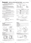
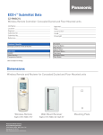
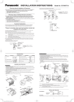
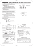
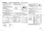
INSTALLATION INSTRUCTIONS Warnings about Installation of Receivers The wireless remote uses a very weak infrared light for its signal, which can result in the signal not being received because of the following influences, so take care in where the unit is installed. • Inverter or rapid-start type fluorescent lights. (Models without glow lamps) • Plasma display or LCD televisions. • Direct sunlight or other sources of bright light. Model No. CZ-RWSC1U If a group of units are to be controlled by 2 remote controllers; ※ Main/sub remote controllers will work regardless of which indoor unit they are installed to. Cross-wiring Remotes for Group Control (Field Supply) Wireless Remote Controller 㧯㧺㧝 㧝 㧞 Use wiring of AWG#20 – AWG#14 for field supply. Make the total wire length when crosswiring a group no more than 650 ft. Wired Remote Controller ※ (Main) ※ (Sub) 㧝 㧞 Warnings about Installing Remote Controllers If a remote controller is to be operated from a remote control holder that is hung on a wall, turn on the lights in the room as well as any electrical appliances and then check to make sure the air conditioner works with the remote controller in the location where it will be installed. If it works, continue with installation. If the air conditioner is to be switched from the main sensor to a remote control sensor, pay attention to the following when installing. • Locate where no warm or cold drafts will affect it. • Locate in a place free from direct sunlight. • Locate where it will not be affected by any other heat/cold source. 1st Indoor Unit 2nd Indoor Unit 3rd Indoor Unit 4th Indoor Unit CZ-RWSC1U Customer Explanation RCU: MAIN →RCU: SUB Give the Operating Instructions and this manual to the customer after finishing the installation. Use the Operating Instructions to explain to the customer how to use and care for the unit. Things to remember when wired and wireless remotes are installed at the same time Two remote controllers can be used to control the unit if the wireless remote controller is installed at the same time as the wired remote controller. (Up to 2 remotes [a wireless remote controller and the wired remote controller] can be installed.) When using 2 remotes, one or more units can be operated by the remotes. <Note> When wiring remote controllers, be sure to double-check the terminal numbers of the indoor unit before connecting them so there are no mistakes in the wiring. (Damage will occur if high voltage [e.g. supply voltage] is applied.) <Note> It is not possible to use more than one wireless remote controller with one indoor unit. (A receiver located separately can be used at the same time.) <Note> If both a wireless and a wired remote controller are to be installed and used at the same time, one of them must be set up as the sub remote controller. If the wired remote controller is to be the sub remote, change the wired remote controller to the sub remote. If the wireless remote controller is to be the secondary, turn the #3 switch on the wireless receiver (operation panel) from OFF to ON. When 1 indoor unit is operated by 2 remote controllers: ※ Either of the remotes can be set to main/sub. Wired Remote Controller (Sold Separately) ※ (Sub) ※ (Main) Wireless Remote Controller 㧯㧺㧝 㧝 㧞 Receiver 㧝 㧞 Use wiring of AWG#20 – AWG#14 for field supply. Use a total wire length of no more than 1300 ft. Remote Control Wiring (Field Supply) Indoor Unit 1 2 When using a separately installed receiver as an exposed model, attach it to a wall where the receiver can be affixed. Accessories No. 1 Accessories Receiver (Enclosed 7-7/8 in. wiring) Quantity No. 1 7 Operating Instructions 1 8 Truss Self-Tapping Screws 2 Accessories Quantity 2 Remote Controller 1 9 Small screw 2 3 Remote Control Holder 1 10 Wood screw 2 4 Dry-cell Batteries 2 11 Cable tie 1 5 Plate mounting 1 12 Spacer 4 1 Put a slotted screwdriver or the like into the groove on the bottom of the receiver unit and twist it to remove the bottom of the case. (Fig. A) 2 To enable the receiver’s wiring to stick out from the upper part of the case (thin part at center-top), use side-cutters or the like to cut a hole in the case big enough for the remote control wiring (sold separately). (Fig. B) 3 Disconnect the wires that were connected at shipment from the connector. 4 After installing the remote control wiring (sold separately) at the position in Fig. C with the enclosed cable tie, connect it to the connector on the receiver. 5 Shape the remote control wiring at the top of the PCB so it fits inside the receiver and after configuring the wiring like it is in Fig. D, attach the lower case. When doing this, arrange the head of the cable tie so it face sideways. 6 Remove the face plate and use the woodscrews (2) to install the receiver unit. 7 Use the cord clip that comes enclosed with the remote control wiring to fasten it to the wall. 8 Attach the face plate. Fig. A 13 Ceiling installation pattern 6 Screw (M4×1-9/16 in.) Outlet in the upper part of the case for the Remote Control Wiring Fig. B 1 2 Fig. C Cable tie (Enclosed) About 5/64 to 1/8 in. Installing the Receiver When using a separately installed receiver as a built-in model, install it to the switch box (field supply) shown in the diagram on the right, which has been built into the wall on site in advance. Connector Fig. D Cable tie (Enclosed) Remote Control Wiring (Sold Separately) Receiver Unit Woodscrews (2) Remote Control Wiring (Sold Separately) 㧝㧞㧟 㧠㧡㧢 1 Remove the face plate of the receiver by slipping a slotted screwdriver or the like into the cutout on the bottom. 2 Install the receiver with the 2 enclosed small screws. 3 Connect the receiver’s wiring (2 cores) with the wiring from the indoor unit. (Refer to the chapter on wiring the receiver) When wiring receivers, be sure to double-check the terminal numbers of the indoor unit before connecting them so there are no mistakes in the wiring. (Damage will occur if high voltage [e.g. supply voltage] is applied.) 4 Attach the face plate. Receiver Unit Small screws (2) Spacers Single outlet switch box (no cover) Cutout Face Plate 3 Panasonic_INST MANUAL_CZ-RWSC1U.indd 1 4 2012/01/25 13:38:07 When using a receiver that has been installed separately into the ceiling, use the plate mounting. Fig. A Fig. B Fig. C If it is to be used as an exposed model: Wiring Diagram Screws (2) (M4×1-9/16 in.) Part A Terminal strip for wiring the Remote Controller of the indoor unit 㧝 White Black 㧞 㧝 㧞 Receiver Remote Control Wiring (Sold Separately) Use remote control wiring (sold separately) for wiring a separately installed receiver. 1. For instructions on how to install a remote control wiring (sold separately), refer to the chapter on Using as an Embedded Model in Installing Separate Receivers. 2. If a remote control wiring (sold separately) is to be used, refer to the Mounting Instructions attached to the remote control wiring. Part B Plate mounting 1. 2. 3. 4. 5. Remove the face plate of the receiver by slipping a slotted screwdriver or the like into the cutout on the bottom. Cut out a hole in the ceiling to match the dimensions of the ceiling installaion pattern. Pass the wiring through the plate mounting and put it into the hole. (Fig. A) Bend parts A and B of the plate mounting so they hold onto the ceiling firmly. (Fig. B) Connect the receiver’s wiring (2 cores) with the wiring from the indoor unit. (Refer to the chapter on wiring the receiver.) When wiring receivers, be sure to double-check the terminal numbers of the indoor unit before connecting them so there are no mistakes in the wiring. (Damage will occur if high voltage [e.g. supply voltage] is applied.) 6. Adjust the enclosed spacers so they are several millimeters thicker than the ceiling material and hold the receiver in place temporarily with the 2 enclosed small screws. 7. Bend parts A and B back so they fit in the opening and are in the gap between the surface of the ceiling and the receiver; then tighten the screws. Do not use too much force when tightening the screws. Doing so may warp or damage the case. Move the receiver by hand and check that it can move just a little. (Fig. C) 8. Attach the face plate. Wiring the Receiver Terminal strip for wiring the Remote Controller of the indoor unit Address Display on the Remote Controller ・・・・・ It doesn’t matter where the receiver’s address switch is. 㧝㧞㧟 㧝㧞㧟 㧠㧡㧢 㧠㧡㧢 㧝㧞㧟 ・・・・・ 㧠㧡㧢 Connections 㧝 Test Operation 㧝 㧞 White Black 㧞 Implementing a Test Run Receiver Receiver wires (field supply) Wires from the receiver unit Enclosed wire joints (2, white) Receiver wires (field supply) Setting Address Switches When more than one receiver and remote controllers are installed in the same room, setting up addresses allows them to avoid interfering with each other. Refer to the Operating Instructions for information on how to change the addresses of the remote controllers. Changing the address of a receiver can be done after removing the screw to the receiver’s PCB cover. Once the change is complete, put the cover back in place; while holding the wiring with the cable clamp, tighten its screw. Position of the Receiver’s Address Switch Use wiring of AWG#20 – AWG#14 for field supply. Use a total wire length of no more than 1300 ft. Polarity does not matter. If to be used as an embedded model; Wiring Diagram <Note 1> When wiring remote controllers, be sure to double-check the terminal numbers of the indoor unit connecting them so there are no mistakes in the wiring. (Damage will occur if high voltage [e.g. supply voltage] is applied.) <Note 2> If the wiring to the operation panel is bundled together with other wiring, such as the incoming line from the power source, it can cause a malfunction, so avoid doing so. <Note 3> If something causes the unit’s power source to make noise, it will be necessary to resolve the problem, such as by installing a noise filter. 1. Strip the wire to be connected of its sheathing for 35/64 in. 2. Twist the two wires together and crimp the enclosed wire joint. 3. If a special crimping tool is not used, or if the connection is made using solder, wrap the joint with insulating tape. Receiver wires (field supply) 1. Remove the face plate of the receiver’s PCB and turn the DIP switch to RUN/On (Down → Up) and operate the wireless remote controller with its Start/Stop button. 2. During a test run, all display lamps on the display will light up. 3. During a test run, it is not possible to adjust the temperature. 4. After completing a test run, be absolutely sure to return the Test Run switch to OFF (Up → Down) and make sure none of the display lamps are blinking. Also, put the face plate back in place. <Note 1> This is hard on the device, so only use this for the test run. <Note 2> After turning on the power, the unit will not receive any commands from the remote controller for about 1 minute. This is not an error. (In fact it does receive signals, but they are cancelled.) <Note 3> Make sure to operate while the indoor unit is stopped. <Note 4> The address of indoor unit is set to “ALL” at the time of the shipment. Wire joint (Enclosed) 5 6 The Self-Diagnosis Function Display and What is Detected Alarm Display in the table below indicates the content of alarms that are displayed when a wired remote controller is connected. For information on how to deal with the alarms, refer to the Mounting Instructions for the indoor unit or to Test Run or servicing materials. Error Detected WL Remote Control LED Display Alarm Display Run Timer Standby Communication error in the remote control E01–E03, E08–E14, E17, E18 circuit Communication error either in the in/ E04–E07, E15, E16, E19–E31 outdoor operation line or the sub-bus of the outdoor unit Operation of indoor protection device P01, P09–P14 ◎ ● ● ● ● ◎ ● ◎ ◎ Alternately Operation of outdoor protection device P02–P08, P15–P31 ◎ ● ◎ Alternately Error in the indoor thermistor F01–F03, F10–F11 ◎ ◎ ● Alternately Error in the outdoor thermistor F04–F09, F12–F28 ◎ ◎ ○ Alternately Error in the indoor EEPROM F29 ◎ ◎ ● Simultaneously Error in the outdoor EEPROM F30, F31 ◎ ◎ ○ Simultaneously Error related to the compressor H01–H31 ● ◎ ● Error in indoor settings L01–L03, L05–L09 ◎ ● ◎ Simultaneously Error in outdoor settings L04, L10–L31 ◎ ○ ◎ Simultaneously Inconsistency in Air/Heat (Including an auto-temp setting for a model without auto-temp settings) Oil Alarm (Same as operation of outdoor protection device) ○ ◎ ◎ Alternately ◎ ● ◎ Alternately Test Run ◎ ◎ ◎ Setting Up Remote Control Functions The functions of the wireless remote can be set on site. (These settings are saved in nonvolatile memory in the remote controller, so even when its batteries are changed, the settings do not revert to the defaults.) <Note> Blinking The operation of the air conditioner can be impacted, depending on the settings made, so only service personnel should make the settings. Furthermore, making changes to these settings may cause actual operation to deviate from what is printed in the Operating Instructions, so be sure to explain this to the customer fully. Making Settings (Do with unit stopped.) 1. Holding down the Swing/Wind Direction + OFF Timer + Mode Select buttons at the same time for 4 or more seconds makes the display switch to the setting screen. (See Diagram Below.) 2. Use the Temperature setting buttons, / , to select the number of the item to be set. 3. Use the ON Timer buttons, / , to change settings. 4. The settings are saved with the Once/Every Day button. When this is done, the settings display of the LCD changes from blinking to light. 5. If other settings are to be changed as well, repeat steps 2 to 4. 6. When all settings have been made, press the Start/Stop button. Example: Operation mode setting screen Item Number & Setting Item Item Number 1 Operation Mode 2 Flap Display Setting Content Setting when Shipped (No Display) (Note 1) Simultaneously 3 Select Fan Speed 4 5 Display of Set Temperature Time Display 6 Ventilation Fan ON/OFF Off (No Display) (No Display) 6 ● : Off / ○ : On / ◎ : Blinking (0.5 sec. intervals) °F Setting Off (Note 2) AM/PM °C °F 24 Hour (No Display) AM/PM On OFF (Note 3) 2 Room Temperature Sensor Settings Common to All Models The indoor unit and the wireless remote controller are equipped with indoor temperature sensors. The sensing of indoor temperature works via one of them. When the unit is shipped, it is set to the indoor unit, but to switch to the remote controller, press the sensor button (diagram at right) inside the remote controller’s cover and then check to make sure that Main Sensor on the LCD screen goes off. <Note> Even when the sensor switch has been set to the remote controller, if the unit does not receive any room temperature data from the remote controller for ten minutes, it automatically switches back to the indoor unit sensor, so be sure to install the remote controller facing the receiver. 7 Cool temp Max 41 – 95°F 86°F 3 8 Cool temp Min 41 – 95°F 64°F 9 Heat temp Max 41 – 95°F 78°F (Note 4) 4 10 Heat temp Min 41 – 95°F 60°F 11 Dry temp Max 41 – 95°F 86°F 12 Dry temp Min 41 – 95°F 64°F 13 Auto temp Max 41 – 95°F 80°F 14 Auto temp Min 41 – 95°F 62°F 16 Address Setting Max Value 00 (ALL only) 1 Sensor Button 01 – 31 06 (Note 5) 17 Heat temp Max ON/OFF JP (Heater Max Temp Change Off) EP (On) Note 1 Note 2 Note 3 Note 4 Note 5 JP While the unit is in the swinging mode (Swing/Wind Direction), the flap cannot be stopped in a desired position. When Setting OFF is selected, “°C” is displayed on the LCD screen. You can toggle between ON and OFF by pressing Ventilation for 4 seconds or more. If the Heater Max ON/OFF setting is not changed to EP (ON), the setting change will not be reflected. This is the number of addresses that can be set in the address change mode. Do not set it to 07 or above. Printed in Japan 7 Panasonic_INST MANUAL_CZ-RWSC1U.indd 2 8 85464369519011 2012/01/25 13:38:08