1
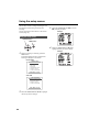
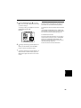
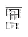
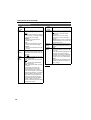
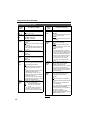
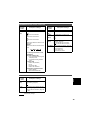
Panasonic Broadcast
AG-DVX100B
Menu Information
Using the setup menus
Use the setup menus to change the settings to suit
the scenes you are shooting or what you are
recording.
You can also use the menu buttons on the remote
control. (Page 19)
3
Example:
Using the setup menus
OPERATION lever
MENU button
4
CAMERA MENU
1 . SCENE FILE
2
3
4
5
6
7
. CAMERA SETUP
. SW MODE
. AUTO SW
. RECORDING SETUP
. DISPLAY SETUP
. OTHER FUNCTIONS
PUSH MENU TO EXIT
VCR mode
VCR FUNCTIONS
1 . PLAYBACK FUNCTIONS
2
3
4
5
. RECORDING SETUP
. AV IN/OUT SETUP
. DISPLAY SETUP
. OTHER FUNCTIONS
PUSH MENU TO EXIT
66
Move the OPERATION lever e or r to
highlight the item you want to change.
Example:
When not shooting or recording, press the
MENU button.
The camera enters the menu mode and the
following is displayed on the screen.
Camera mode
2
MENU
1
Press the OPERATION lever (h) (or move it
y) to display the items.
Move the OPERATION lever e or r to highlight
the item you want to change.
Press the OPERATION lever (h) (or move it
y), then move it e or r to select the setting
you want to change.
To change a setting, move [q], then move the
OPERATION lever e or r.
Example:
6
To change other settings, repeat steps 4 and
5.
When you have finished, press the MENU
button to return to the function screen.
7
To change other settings, repeat steps 2 to 5.
When the menu mode is finished, press the
MENU button again and return to the normal
screen.
Initializing the menu settings
The setup menus are divided into user files and
scene files. You can initialize these separately.
To initialize the user file (all items except the scene
files)
In the OTHER FUNCTIONS screen, USER FILE,
select INITIAL. The settings for the current user file
are returned to the factory settings. (Page 78)
To initialize the scene files
From the 6 scene files, select the one you want to
initialize with the scene dial. Then in the SCENE
FILE screen, SAVE/INIT, select INITIAL. The
settings for the selected scene file are returned to
the factory settings. (Page 70)
There is no effect on the other scene files.
Menus
5
67
Setup menu structure
Camera mode menu
CAMERA MENU
SCENE FILE
(Pages 69 and 70)
CAMERA SETUP
(Page 71)
SYNCRO SCAN
ASPECT CONV
COLOR BAR
SETUP
SW MODE
(Pages 71 and 72)
AUTO SW
(Page 72)
A.IRIS
AGC
ATW
AF
MID GAIN
HIGH GAIN
ATW
HANDLE ZOOM
IRIS DIAL
USER1
USER2
USER3
RECORDING SETUP
(Pages 74 and 75)
DISPLAY SETUP
(Page 76)
OTHER FUNCTIONS
(Pages 77 and 78)
REMOTE
DV CONTROL
DV CMD SEL
END SEARCH
REC LAMP
BEEP SOUND
CLOCK SET
TIME SHIFT
POWER SAVE
LANGUAGE
H.P MODE
FILE TRANS
USER FILE
HOUR METER
ZEBRA DETECT 1
ZEBRA DETECT 2
MARKER
VIDEO OUT OSD
DATE/TIME
LEVEL METER
ZOOM FOCUS
TAPE BATTERY
OTHER DISPLAY
LCD BACKLIGHT
LCD SET
EVF SET
SELFSHOOT
EVF MODE
EVF COLOR
DISPLAY ASPECT
DETAIL LEVEL
V DETAIL LEVEL
DETAIL CORING
CHROMA LEVEL
CHROMA PHASE
COLOR TEMP
MASTER PED
A. IRIS LEVEL
GAMMA
KNEE
MATRIX
SKIN TONE DTL
V DETAIL FREQ
PROGRESSIVE
NAME EDIT
SAVE/INIT
REC SPEED
AUDIO REC
MIC ALC
MIC GAIN 1
MIC GAIN 2
TC MODE
TCG
FIRST REC TC
TC PRESET
UB MODE
UB PRESET
ONE-SHOT REC
REC TIME
VCR mode menu
VCR FUNCTIONS
PLAYBACK FUNCTIONS
(Page 73)
RECORDING SETUP
32K (12bit) AUDIO
AUDIO OUT
(Pages 74 and 75)
AV IN/OUT SETUP
A. DUB INPUT
DV OUT
DISPLAY SETUP
DATE/TIME
LEVEL METER
TAPE BATTERY
OTHER DISPLAY
VIDEO OUT OSD
CAMERA DATA
LCD BACKLIGHT
LCD SET
EVF SET
EVF MODE
EVF COLOR
DISPLAY ASPECT
(Page 75)
(Page 76)
OTHER FUNCTIONS
(Pages 77 and 78)
68
REC SPEED
AUDIO REC
1394 TC REGEN
TC MODE
TCG
FIRST REC TC
TC PRESET
1394 UB REGEN
UB MODE
UB PRESET
DV IN PRESET
REMOTE
END SEARCH
CLOCK SET
TIME SHIFT
LANGUAGE
USER FILE
FILE RECEIVE
HOUR METER
Setup menu list
SCENE FILE screen
Description of settings
DETAIL LEVEL Adjusts the amount of detail.
(camera)
-7 - 0 - +7
V DETAIL
LEVEL
(camera)
Adjusts the level of outline correction in
vertical screen.
-7 - 0 - +7
DETAIL
CORING
(camera)
Adjusts the level of removing noises of
the detail signal.
-7 - 0 - +7
Set to - for a clearer image. Noise
increases slightly.
Set to + to decrease noise.
CHROMA
LEVEL
(camera)
Adjusts chroma level.
-7 - 0 - +7
CHROMA
PHASE
(camera)
Finely adjusts chroma phase.
-7 - 0 - +7
COLOR TEMP
(camera)
Finely adjusts color temperature (after
adjusting white balance).
-7 - 0 - +7
MASTER PED
(camera)
Adjusts the black master pedestal as
the basis for images.
-15 - 0 - +15
A. IRIS LEVEL
(camera)
Sets AUTO IRIS level.
-4 - 0 - +4
Item/
Display
mode)
GAMMA
(camera)
Description of settings
Selects gamma curve.
LOW:
Using the gamma curve, which the
slope of low-brightness is modest,
makes it staid image. The contrast
become sharp.
NORMAL:
Makes standard images.
HIGH:
Using the gamma curve, which the
slope of low-brightness is modest,
spreads out the tone of dark parts
and makes it bright image. The
contrast become soft.
B.PRESS:
Makes the contrast sharper than
LOW.
CINELIKE:
Uses the gamma curve to complete
the cine-line image. Images have
less noise than CINELIKE_D.
CINELIKE_D:
Dynamic range is higher than
CINELIKE.
CINELIKE_V:
Uses the gamma curve to complete
the cine-like image of the emphasis
on contrast.
• When CINELIKE Gamma is selected,
we recommend that the lens aperture
is set to the lower level (about 1/2)
than normal image level for making
full use the characteristics.
KNEE
(camera)
To avoid an over exposure, use this to
set the compression level (knee point)
of the high-intensity video signals
which the CCD received.
AUTO:
Sets the level automatically
according to the received signals.
LOW:
Low setting (compression begins
from approximately 80%)
MID:
Medium setting (compression begins
from approximately 90%)
HIGH:
High Setting (compression begins
from approximately 100%)
Menus
Item/
(Display
mode)
are the factory settings.
69
Setup menu list (continued)
SCENE FILE screen
Item/
(Display
mode)
MATRIX
(camera)
70
Description of settings
Chooses a MATRIX table, and sets the
color for shooting.
NORM:
Makes colors suitable for a shooting
in the open air or in using a halogen
lamp as the source of light.
ENRICHED:
Makes colors brighter than the
NORM1 mode.
FLOU:
Makes colors suitable for shooting
indoors under fluorescent lights.
CINE-LIKE:
Makes colors suitable for movie-like
shooting.
SKIN TONE
DTL
(camera)
Sets the skin tone details to ON or
OFF. When ON is selected, skin tone
details are reduced, which softens the
skin tones.
ON OFF
V DETAIL
FREQ
(camera)
Sets the vertical detail when shooting
in progressive mode.
THIN : Select this to thin the detail of
images.
MID : Select this to slightly thicken
the detail of images.
THICK : Select this to thicken the detail
of images.
• When images were shot in the
progressive mode in which the
vertical detail is set as “THIN” or
“MID” and are played on a monitoring
television (60i interlace), you will feel
flickers caused on horizontal lines
and almost horizontal oblique lines.
When you play images under the
progressive mode, set the detail as
“THIN” or “MID”. This gives you
higher resolution images than setting
the detail as “THICK”.
Item/
(Display
mode)
Description of settings
PROGRESSIVE Sets the shooting in progressive mode.
(camera)
OFF: Select this to disable progressive mode.
30P: Select this to shoot in 30P mode (30
frames/second).
24P: Select this to shoot in 24P mode (24
frames/second). The tape is recorded in [2:3]
conversion.
24P (ADV): Select this to shoot in 24P advanced
mode (24 frames/second). The tape is recorded
using advanced conversion.
NAME EDIT
(camera)
Edits the name of the selected scene
file you have selected with the scene
file dial.
SAVE/INIT
(camera)
SAVE:
The changed settings in the scene file
are saved.
• The original scene file settings will be
restored when the menu mode is
released, the operation is switched to
the VCR mode or when the power is
turned off if you do not select SAVE.
INITIAL:
The selected scene file settings in the
SCENE FILE dial are returned to the
factory settings.
are the factory settings.
Item/
(Display
mode)
Description of settings
SYNCRO SCAN Adjusts the synchro scan shutter
speed used for shooting images on a
(camera)
TV screen, etc.
If you move and hold the OPERATION
to e or r, changing speeds up and a
beep sounds.
• PROGRESSIVE MODE OFF:
1/60.3 1/250.0
• PROGRESSIVE MODE 30P:
1/30.1 1/48.0 1/250.0
• PROGRESSIVE MODE 24P/24PA:
1/24.1 1/48.0 1/250.0
SW MODE screen
Item/
(Display
mode)
MID GAIN
(camera)
Sets the gain value which is to be
allocated to the M position of GAIN
switch.
0dB 3dB 6dB 9dB 12dB
HIGH GAIN
(camera)
Sets the gain value which is to be
allocated to the H position of GAIN
switch.
0dB 3dB 6dB 9dB 12dB
ATW
(camera)
Sets the operation of the ATW (Auto
Tracking White) function which is to be
allocated to the WHITE BAL switch.
OFF:
Disables the ATW function. However,
if the ATW function is set to the
AUTO button or USER button, the
operation of that button becomes
effective.
Ach:
Activates the ATW function when the
WHITE BAL switch is set to A.
Bch:
Activates the ATW function when the
WHITE BAL switch is set to B.
PRE:
Activates the ATW function when the
WHITE BAL switch is set to PRST.
HANDLE
ZOOM
(camera)
Sets the zoom speeds allocated to the
setting positions of the HANDLE
ZOOM switch.
L/OFF/H:
Sets LOW (speed) /OFF/HIGH
(speed) to each position of 1/2/3
(zoom is disabled when set to OFF).
L/M/H:
Sets LOW/MID (medium speed)/
HIGH to each position of 1/2/3.
IRIS DIAL
(camera)
Sets the rotation and the aperture
control of the IRIS dial (when in
MANUAL IRIS mode).
DOWN OPEN:
The iris opens when the IRIS dial is
turned downward.
UP OPEN:
The iris opens when the IRIS dial is
turned upward.
ASPECT CONV Selects the aspect ratio of the images
which are to be recorded. (Page 34)
(camera)
NORMAL
LETTER BOX
SQUEEZE
COLOR BAR
(camera)
Sets the color bar to ON or OFF.
ON OFF
• Even if the color bar is set to ON, it
reverts to OFF when the unit is
switched to VCR mode or when the
power is turned off.
SETUP
(camera)
Adds the setup level (black level).
0%:
The setup level is not added.
7.5%:
A 7.5% setup level is added for
recording.
Description of settings
Menus
CAMERA SETUP screen
are the factory settings.
71
Setup menu list (continued)
SW MODE screen
Item/
(Display
mode)
USER1
(camera)
Description of settings
Enables a function to be allocated to
the USER1 button.
COLOR BAR:
Color bar display (Page 35)
SPOTLIGHT:
Sets the auto iris control for the
spotlight to ON or OFF.
BACKLIGHT:
Auto iris control for the backlight
compensation (Page 35)
BLACKFADE:
Blackfade (Page 35)
WHITEFADE:
Whitefade (Page 35)
MODECHECK:
Press the button to check the status
of the current camera setting
displayed on the viewfinder and LCD
monitor.
ATW:
Sets the ATW function to ON or OFF.
ATWLOCK:
Press the button to fix the value of
white balance. Press again and the
ATW function is activated.
GAIN: 18 dB:
Press the button to set the gain
value to 18 dB. This function is
disabled in progressive mode and
slow shutter mode.
• When the gain value is set to 18 dB
or set from 18 dB to another value,
the image can be disordered for a
moment.
INDEX:
INDEX recording (Page 35)
SLOWSHUT:
Slow shutter mode (Page 40)
USER2
(camera)
Enables a function to be allocated to
the USER2 button.
For further details, refer to USER1
above.
BACKLIGHT
USER3
(camera)
Enables a function to be allocated to
the USER3 button.
For further details, refer to USER1
above.
INDEX
AUTO SW screen
Item/
(Display
mode)
Description of settings
A.IRIS
(camera)
ON:
Performs auto iris control when in
auto mode. The IRIS button is
disabled.
OFF:
Disables the auto iris control when in
auto mode. This performs the iris
control selected with the IRIS button.
AGC
(camera)
Sets the Auto Gain Control function for
when the A. IRIS option is set to ON.
6dB:
Enables the Auto Gain Control
function (max 6 dB) when the Auto
Mode is selected.
12dB:
Enables the Auto Gain Control
function (max 12 dB) when the Auto
Mode is selected.
OFF:
Disables the Auto Gain Control
function when the Auto Mode is
selected.
ATW
(camera)
ON:
Enables the ATW (Auto Tracing
White Balance) function when the
Auto Mode is selected. You can’t
enable or disable the ATW function
with the WHITE BAL switch or the
USER button when this is selected.
If ATWLOCK is assigned to the
USER button, however, you can set
the White Balance value with the
USER button.
OFF:
Disables the ATW function when the
Auto Mode is selected. The ATW
function that has been selected with
the WHITE BAL switch applies.
AF (camera)
ON:
Performs auto focus when the auto
mode is established. Neither
FOCUS switch nor the PUSH AUTO
button works.
OFF:
Performs no auto focus when the
auto mode is established. The
focusing is performed by the FOCUS
switch or PUSH AUTO button.
are the factory settings.
72
PLAYBACK FUNCTIONS screen
Item/
(Display
mode)
32K (12bit)
AUDIO (VCR)
Item/
(Display
mode)
Description of settings
AUDIO OUT
(VCR)
Sets the sound to be output as CH1
and CH2 signals when playing back a
tape that was recorded in the 32K
(12bit) audio mode.
ST1:
Selects the sound that was recorded
during shooting.
CH1 signals = CH1 track
CH2 signals = CH2 track
ST2:
Selects the sound that was dubbed
on the recording.
CH1 signals = CH3 track
CH2 signals = CH4 track
MIX:
Mixes the sound that was recorded
during shooting and the sound that
was dubbed on the recording.
CH1 signals = CH1 track + CH3
track
CH2 signals = CH2 track + CH4
track
Note
When the sound is recorded in the 48K
(16bit) audio mode, CH3 and CH4 do
not exist so the following is always the
case.
CH1 signals = CH1 track
CH2 signals = CH2 track
Description of settings
Sets the audio signals to be output
from the AUDIO IN/OUT pin jack when
the tape is played back.
CH1•CH2:
CH1 output = CH1 signals
CH2 output = CH2 signals
CH1:
CH1 output = CH1 signals
CCH2 output = CH1 signals
CH2:
CH1 output = CH2 signals
CH2 output = CH2 signals
are the factory settings.
Audio recording
mode
32K (12bit)
48K (16bit)
32K (12bit) AUDIO
item setting
AUDIO OUT item
setting
AUDIO IN/OUT jack
CH1 output
AUDIO IN/OUT jack
CH2 output
ST1
CH1•CH2
CH1
CH2
CH1
CH1
CH2
CH2
CH1
CH2
ST2
CH1•CH2
CH1
CH2
CH3
CH3
CH4
CH4
CH3
CH4
MIX
—
CH1+CH3
CH2+CH4
—
CH1•CH2
CH1
CH2
CH1
CH1
CH2
CH2
CH1
CH2
Menus
32K (12bit) AUDIO item/AUDIO OUT item settings and audio track signals output from the AUDIO IN/
OUT jack
73
Setup menu list (continued)
RECORDING SETUP screen
Item/
(Display
mode)
Description of settings
REC SPEED
(camera)
(VCR)
Set the recording-time mode.
SP: SP (standard) mode
LP: LP (long) mode
AUDIO REC
(camera)
(VCR)
Set the audio recording mode for conversion to PCM audio.
32K (12bit): 12bit/21kHz
48K (16bit): 16bit/48kHz
MIC ALC
(camera)
Sets microphone level auto control to
ON or OFF.
ON OFF
Set this ON to reduce distortion at high
input levels.
• You should also adjust the input level
with the AUDIO control whatever you
set here.
MIC GAIN 1
(camera)
Sets the input level of the external
microphone connected to the INPUT 1
terminal.
-50dB -60dB
MIC GAIN 2
(camera)
Sets the input level of the external
microphone connected to the INPUT 2
terminal.
-50dB -60dB
1394 TC
REGEN
(VCR)
Selects the time code used when signals from equipment connected with
the DV terminal is recorded.
ON:
Records with the time code signal
input through the DV terminal.
OFF:
Records with the time code set at TC
MODE/TCG/FIRST REC TC.
• This setting has priority over any
setting you have made in TC MODE/
TCG/FIRST REC TC.
• If there is no input to the DV terminal,
the setting follows the ones set at TC
MODE/TCG/FIRST REC TC.
TC MODE
(camera)
(VCR)
Selects the correction mode of the
internal time code generator.
DF
: Uses the drop frame mode.
NDF : Uses the non-drop frame
mode.
• The non-drop frame mode will be
used when you are shooting in a
progressive mode, 24P or 24P (ADV).
Item/
(Display
mode)
TCG
(camera)
(VCR)
Description of settings
Use this to set the mode in which to
advance the time code.
FREE RUN:
The time code advances regardless
of the operation mode.
REC RUN:
The time code advances only when
recording.
FIRST REC TC Select the time code to be recorded
when you start recording.
(camera)
(VCR)
REGEN:
Select to record the time code so
that it continues from the time code
already on the tape.
PRESET:
The time code does not continue
from the time code on the tape. The
value you set at TC PRESET is used
as the initial value when recording
the time code. The time code does
continue on from the one on the
tape, however, if you continue
recording from something on the
tape.
TC PRESET
(camera)
(VCR)
Sets the initial time code. This is
effective when you have select
PRESET in FIRST REC TC.
• Set the frame value to 0 or a multiple
of 5 when you are shooting in a
progressive mode, 24P or 24P (ADV).
Using any other value will cause the
time code to differ.
1394 UB
REGEN
(VCR)
Selects the user information used
when signals from equipment connected with the DV terminal is
recorded.
ON:
Records with the user information
signal input through the DV terminal.
OFF:
Records the user information set
with UB MODE.
• If you select ON here, this has priority
over the settings in UB MODE.
• If the signal has no user information,
the none is recorded.
• If there is no signal being input
through the DV terminal, then the UB
MODE settings are used.
is the factory setting.
74
RECORDING SETUP screen (continued)
Item/
(Display
mode)
UB MODE
(camera)
(VCR)
Description of settings
Set the information you want for user
information.
USER:
Records user information.
TIME:
Records the current time.
DATE:
Records the current date.
TCG:
Records the data from the time code
generator.
FRM. RATE:
Records the frame conversion frame
rate.
a
b
c
d
Item/
(Display
mode)
Description of settings
UB PRESET
(camera)
(VCR)
Set user information. Make sure you
have set USER in UB MODE.
ONE-SHOT
REC
(camera)
Set ONE-SHOT recording mode.
(Page 34)
ON:
OFF:
REC TIME
(camera)
Sets the length of time for ONE-SHOT
recording. (Page 34)
0.5s: 0.5 seconds 1s: 1.0 second
1.5s: 1.5 seconds 2s: 2.0 seconds
DV IN PRESET Synchronizes the camera’s TCG with
the TC from DV input when you press
(VCR)
the TC SET button.
ON: The mode is on.
OFF: Cancels the mode.
a: Checking information for user
information
b: Frame sequence No.
• 0 to 4 are displayed during 24P/
24P (ADV) mode.
• F is displayed during 60i/30P
mode.
c: Frame rates
• Frame rate (60/30/24)
• I/P ID
• Conversion data
• Frame rate coefficient
d: Recording management data
• Frame updates
• REC START/STOP data
AV IN/OUT SETUP screen
Description of settings
A DUB INPUT
(VCR)
Selects the sound to be recorded for
audio dubbing. (Page 56)
MIC:
A_IN:
DV OUT
(VCR)
Select ON to convert analog input signals into digital signals and output
them from the DV connector. (Page 58)
ON OFF
Menus
Item/
(Display
mode)
are the factory settings.
75
Setup menu list (continued)
DISPLAY SETUP screen
Item/
(Display
mode)
Description of settings
ZEBRA
DETECT 1
(camera)
Sets the brightness level of the leftleaning zebra patterns on the screen.
80%, 85%, 90%, 95%, 100%, 105%
ZEBRA
DETECT 2
(camera)
Sets the brightness level of the rightleaning zebra patterns on the screen.
80%, 85%, 90%, 95%, 100%, 105%, OFF
Note
The zebra patterns do not appear if
you select OFF.
MARKER
(camera)
Select ON to display the marker.
ON OFF
• To display the marker, press the
ZEBRA button. (Page 33)
VIDEO OUT
OSD
(camera)
(VCR)
DATE/TIME
(camera)
(VCR)
Item/
(Display
mode)
Description of settings
CAMERA DATA Select ON to show the camera settings
(such as image stabilizer, F-number,
(VCR)
and gain value) during tape playback.
OFF ON
LCD BACKLIGHT
(camera)
(VCR)
Adjusts the backlight of the LCD monitor. Select HIGH for a brighter backlight
than usual.
HI NORMAL
LCD SET
(camera)
(VCR)
Adjusts the display level of the images
on the LCD monitor. (Page 25)
LCD COLOR LEVEL:
LCD BRIGHTNESS:
LCD CONTRAST:
Select ON to output information displayed in the viewfinder and LCD monitor together with the signals from the
VIDEO IN/OUT jack.
ON OFF
EVF SET
(camera)
(VCR)
Adjusts the display level of the images
on the viewfinder. (Page 25)
EVF COLOR LEVEL:
EVF BRIGHTNESS:
EVF CONTRAST:
Sets whether to display the date and
time on the screen and whether to output from the VIDEO IN/OUT jack.
OFF: The date and time are not displayed.
TIME: The time is displayed.
DATE: The date is displayed.
TIME&DATE: The time and date are displayed.
• If you select any setting other than
OFF, the date and/or time are
included in the image output signals
regardless of the VIDEO OUT OSD
setting.
SELFSHOOT
(camera)
Select the LCD mirror mode for selfportrait shooting. Select MIRROR to
reverse left and right during self-portrait shooting.
NORMAL MIRROR
EVF MODE
(camera)
(VCR)
Select when to show images on the
viewfinder.
ON:
Images always appear on the
viewfinder.
AUTO:
Images do not appear on the
viewfinder when the LCD is open.
EVF COLOR
(camera)
(VCR)
Select color or black and white for the
images on the viewfinder.
ON: Color
OFF: Black and white
DISPLAY
ASPECT
(camera)
(VCR)
Select the aspect ratio of the LCD
monitor and viewfinder.
AUTO: Changes automatically to suit
the recording or play mode.
4:3: Fixed at 4:3
16:9: Fixed at 16:9
There is a 10% overscan on the LCD
when the setting is 16:9 (but not on the
viewfinder). You will see the whole
image on both the LCD and viewfinder
when the setting is 4:3.
LEVEL METER Select ON to display the audio level
meter.
(camera)
(VCR)
ON OFF
ZOOM FOCUS
(camera)
Select ON to display the zoom and
focus values.
ON OFF
TAPE BATTERY
(camera)
(VCR)
Select ON to display the remaining
tape and battery charge.
ON OFF
OTHER DISPLAY
(camera)
(VCR)
Select how much information to display. (Page 65)
OFF, PARTIAL, ALL
are the factory settings.
76
OTHER FUNCTIONS screen
Description of settings
REMOTE
(camera)
(VCR)
Sets the operations of the supplied
remote control unit. (For settings on the
remote control (Page 20)
VCR1:
Accepts commands from a remote
control set to VCR1.
VCR2:
Accepts commands from a remote
control set to VCR2.
OFF:
Operations are not accepted from
any remote control.
DV CONTROL
(camera)
Sets the control method for backup
recording with a backup unit connected
to the DV connector.
OFF:
The backup unit is not controlled.
EXT:
The backup unit can be controlled by
the START/STOP button. The
images shot by the video camera are
stored in the backup unit. Note that
the video camera does not record
them.
BOTH:
The images shot by the video
camera are recorded by both the
video camera and backup unit.
CHAIN:
When the video camera’s tape
approaches its end during shooting,
the backup unit set in the recording
stand-by mode automatically starts
to record the images.
DV CMD SEL
(camera)
END SEARCH
(camera)
(VCR)
Sets how the START/STOP button
works for the backup unit.
REC_P:
The button works as a REC/REC
PAUSE button.
STOP:
The button works as a REC/REC
STOP button.
Note
If the backup unit does not have a rec
pause function, select STOP.
Sets the operation to be performed
when a blank search is conducted.
(Page 51)
BLANK:
REC END:
Item/
(Display
mode)
Description of settings
REC LAMP
(camera)
Sets lighting of the tally lamp.
OFF:
Tally lamp does not light.
FRONT:
Front tally lamp (microphone side)
lights.
REAR:
Rear tally lamp (viewfinder side)
lights.
BOTH:
Both tally lamps light.
BEEP SOUND
(camera)
Selects ON/OFF for the beeps.
ON OFF
Select ON to be warned by a beep in
the following situations.
• When a beep sounds, the audio
signals from the OUT jack are muted
and the beep is output instead.
One beep
• when you set the power switch to
ON
• when you start shooting
Two beeps
• when you pause shooting
Three beeps
• when you have set the cassette
tape write-protect
• when condensation has formed
inside the camera-recorder
• when a problem has occurred in
the camera-recorder
Ten beeps
• when it is not possible to record to
the tape
CLOCK SET
(camera)
(VCR)
Sets the camera-recorder’s calendar.
TIME SHIFT
(camera)
(VCR)
The time set using this item is added to
the clock time of the internal calendar
(time difference compensation) and
displayed on the screen. The added
time is also recorded on the tape.
+23h - +1h, OFF, -1h - -23h
(In 1-hour increments)
Menus
Item/
(Display
mode)
are the factory settings.
77
Setup menu list (continued)
OTHER FUNCTIONS screen
Item/
(Display
mode)
POWER SAVE
(camera)
78
Description of settings
Select the power saving mode.
When you don’t perform any specified
operations for five minutes*
ON: the camera recorder turns off
automatically.
OFF: the cylinder head pauses and
goes into standby mode without cutting
the power.
*The camera recorder does not go into
power save mode if you use the following controls.
• AUTO Button
• FOCUS switch
• PUSH AUTO button
• GAIN switch. WHITE BAL switch
• WHITE BAL switch
• IRIS button and dial
• CH1/CH2 SELECT switch
• INPUT1/2 switch
• AUDIO control
• OIS button
• SHUTTER button
• SPEED SEL button
• Zoom button and ring
• HANDLE ZOOM switch
• Opening or closing the LCD
HP MODE
(camera)
Select headphone output.
TAPE:
Sound recorded on the tape is
output.
LIVE:
Current input is output.
The beep sound is not output even if
you have selected ON for BEEP
SOUND. Use this when you are
shooting in the 24P mode or any
other time that sound delay becomes
noticeable.
USER FILE
(camera)
(VCR)
LOAD:
The previous scene file settings are
loaded.
SAVE:
The changed user file settings are
saved.
INITIAL:
The user file settings are returned to
the factory settings.
• After LOAD or INITIAL, switch
camera-recorder OFF and then back
ON to ensure that the settings take
effect.
Item/
(Display
mode)
Description of settings
FILE TRANS
(camera)
Make settings for scene file transfer.
(Page 47)
SCENE:
Transfer the scene file currently
selected with the SCENE dial.
SCENE ALL:
Transfer all scene files.
USER:
Transfer all user scene files.
Note
When in FILE TRANS mode, only
the menu operation buttons will
function.
FILE RECEIVE
(VCR)
Makes the camera ready to receive
scene files from another camera.
(Page 47)
Note
RECEIVE MODE appears on the screen after
you set this mode.
When in FILE RECEIVE mode, only
the menu operation buttons will
function.
HOUR METER
(camera)
(VCR)
Displays the total running time (a 5digit figure in 1-hour increments) of the
cylinder head.
are the factory settings.