1
UHF100
UHF200
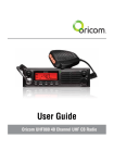
Operating Instructions
For UHF100 and UHF200 40 Channel UHF
2-way Citizen Band Radio
Table of contents
Table of contents...........................................................................3
Safety Information and Warnings...................................................4
Controls and Connectors................................................................5
Installation...................................................................................10
Operations...................................................................................14
UHF channels and frequencies.....................................................30
Warranty information (Australia)...................................................33
This unit complies with all relevant Australian
and New Zealand approval requirements.
3
Safety Information and Warnings
Please read before installing or opearating Your
Oricom Radio
The operation of this radio in Australia and New Zealand is subject to conditions
in the following licenses. In Australia the ACMA Radio communications (Citizen
Band Radio Stations) and in New Zealand by MED General User Radio License
for Citizen Band Radio and operation is subject to conditions contained in those
licences.
Safety Information and Warnings
Potentially Explosive Atmospheres
WARNING Turn your radio OFF when in any area with a potentially explosive
atmosphere. Sparks in such areas could cause an explosion or fire
resulting in injury or even death.
NOTE: Areas with potentially explosive atmospheres are often, but
not always clearly marked. They include fueling areas such as below
deck on boats; fuel or chemical transfer or storage facilities; areas
where the air contains chemicals or particles, such as grain, dust,
or metal powders; and any other area where you would normally be
advised to turn off your vehicle engine.
Blasting Caps and Areas
To avoid possible interference with blasting operations, turn your
radio OFF near electrical blasting caps or in a “blasting area” or
in areas posted: “Turn off two way radios.” Obey all signs and
instructions.
Electromagnetic Interference/Compatibility
Nearly every electronic device is susceptible to electromagnetic
interference (EMI). To avoid the possibility of electromagnetic
interference and/or compatibility conflicts, turn off your radio in any
location where posted notices instruct you to do so such as health
care facilities.
4
Controls and Connectors
Box Contents
UHF100
1 x RF Radio
1 x Remote Head Unit with 2m cable
1 x UHF100 Standard Microphone
1 x DC Power Cord with inline fuse
1 x Mounting bracket with mounting
screws for RF Radio
UHF200
1 x RF Radio
1 x Controller Speaker Micrphone
1 x DC Power Cord with inline fuse
1 x Mounting bracket with mounting
screws for RF Radio
1xM
ount bracket with mounting screw
for Remote Head Unit
1 x Microphone Hanger
1 x User Guide
1 x Microphone Hanger
1 x 2m long Extention cable
1 x Coupler for extention cable
1 x User Guide
5
Controls and Connectors
Front View Remote Head unit (UHF100)
1
2
3
9
4
5
6
1. Microphone connector
2. LCD Display
3. Power On/Off, channel & Volume
control
4. Function button by short push &
Duplex On/Off by long push
5. Open Scan, Memory On/Off, Group
Scan
6
7
8
6. Priority Channel On/Off, Key Lock
On/Off, Alpha-numeric display
7. ID setting, 5 tone SelCall, Quiet
8. Monitor, TSQ On/Off, Menu
9. External speaker Jack (3.5mm for
optional 8 ohm speaker)
Controls and Connectors
Rear View
Rear view of Radio (UHF100 & 200)
1. 3.5mm external jack for optional 8 ohm speaker
2. Power Supply connection
3. Antenna connection
3
2
1
Standard Microphone (UHF100)
1.
2.
3.
4.
Push To Talk (PTT) button
Volume Up, Channel Up
Volume Down, Channel Down
Power On/off, Volume and channel selector
3 4
2
1
7
Controls and Connectors
Top view of Contoller Speaker Microphone (UHF200)
1. Volume Down, Channel Down
2. Volume Up, Channel Up
3. Power On/Off
CH
200RX
1
3
2
Front view of Contoller Speaker Microphone (UHF200)
4.
5.
6.
7.
LCD Display
Function button & Duplex On/Off
Open Scan, Memory On/Off, Group Scan
Priority Channel On/Off, Key Lock
On/Off, Alpha-numeric display
8. ID setting, 5 tone Selcal, Quiet
9. Monitor, TSQ On/Off, Menu
10. PTT Switch
4
9
8
7
6
5
10
8
Controls and Connectors
LCD Icons & Indicators (UHF100 and UHF200)
1
2
3
4
5
6
18
7
8
16
9
10
11
12
1.
2.
3.
4.
5.
6.
7.
8.
9.
13
FUNCTION
RX or TX Signal strength
Transmitter Indicator
Receiver Indicator
Quiet mode
Priority On/Off
Monitor On/Off
Memory On/Off
Key Lock
17
15
14
10. Open Scan
11. Group Scan
12. Selelctive call Sending_to
13. Selective call Receiving from
14. 38 CTCSS Tone On/Off
15. DCS On/Off
16. Channel number
17. ALPHA/NUMERIC
18. Call Alarm
9
Installation
INSTALLATION
CAUTION
When installing your radio in your vehicle, check that during installation you do
not damage any wiring or vehicle components that may be hidden around the
mounting position.
If you are unsure about how to install your radio, we suggest for optimum
performance you have your radio professionally installed by a UHF specialist or
Auto electrician. When installing the radio, avoid mounting it close to heaters or
air conditioners. Do not press the PTT or CALL button before installing the
antenna.
Screw the mounting bracket and the remote head bracket to firm surfaces.
To install the Radio;
1. Fix the radio bracket in a suitable location.
2. Then fix the radio in the bracket using the thumb screws.
Note
The radio contains a built-in loud speaker, The radio can be installed ‘out of the
way’ and an external speaker can be used as an alternative (not supplied).
To mount the Remote Head (UHF100)
The remote head is supplied with a slim mounting bracket and thumb screws.
Its small size and light weight design allows it to be mounted in almost any
convenient position accessible to the driver.
10
Installation
1. Fix the mounting bracket in place by screwing through the slots in the
bracket.
2. Fix the remote head unit to the mounting bracket with the thumb screws
provided.
3. Connect the standard microphone to the remote head socket, and tighten up
the thumb screw.
Fitting the Controller Microphone Speaker (UHF200)
The Remote Head uses an 8 pin telephone style plug and socket:
1. Position the microphone plug so the plastic flap faces downwards, and press
the plug into the socket until it ‘clicks’.
2. Gently press the rubber boot into the hole surrounding the socket so that the
slot around the boot fits neatly inside the rim of the entry hole.
3. If required use the external cable (supplied) to allow the radio to be installed
further from the Controller Speaker Microphone.
11
Installation
Disconnecting the Remote Head/Speaker Controller Microphone
It is recommended that the remote head be left permanently connected to the
radio, but if it must be disconnected, proceed as follows:
1. Lift the rubber boot and the lip of the raised area on the front panel.
2. Ease the rubber boot out of the cable entry hole and slide it along the cable
away from the front panel.
3. Identify the plug locking lever, move the lever towards the plug body. At the
same time gently pull the plug from the socket (see previous page).
Controller Speaker Microphone; part number, CSPKMIC
Standard Microphone; part number, MIC050
These can be purchased from the dealer you purchased the radio from or
directly from Oricom.
DC Power Connection
The Radio is designed for 13.8 Volt DC, negative earth installations only (i.e.
where the negative battery terminal connects to the chassis of the vehicle).
For installation on 24 volt systems an inverter (not supplied) will need to be
used.
There are two possible methods of installation.
Over voltage protection
The radio has a high voltage input detection system, to warn you if an
overvoltage situation occurs.
Eg.: If the power supply voltage exceeds 17volts DC, the channel display (LCD
backlight) will flash in 3 different colors when the unit is turned on.
In additon, when transmitting, the TX indicator will automatically select a low
power output.
If the overvoltage warning appears, you must switch your radio off and
disconnect it from the power source, before locating the cause of the trouble.
The power source must not exceed 30volts.
12
Installation
Radio stays ON when the ignition is switched OFF
Connect the radio's negative (black) lead to the vehicle chassis, or directly to the
batteries negative terminal.
Connect the radio's positive (red) lead via the 2 Amp fuse to the battery's
positive terminal. Alternatively, the positive lead could be connected at the fuse
box at a point that has +13.8 Volts continuously available (preferably the battery
side of the ignition switch) via the 2 Amp fuse.
Radio turns OFF with the ignition switch
Connect the radio's negative (black) lead to the vehicle's chassis, or directly to
the batteries negative terminal.
The radio's positive (red) lead should connect to an accessory point in the
vehicle's fuse box via the 2 Amp fuse.
Antenna information
The antenna (not supplied) is of critical importance, to maximize your output
power and receiver senstivity.
A poor quality antenna or one not designed for the specific frequency band
you are using will give poor performance. You should purchase an antenna
designed for the 477MHz frequency band.
Antenna installation
1. Connect the antenna to the rear antenna socket using a PL259 coaxial connector.
2. To obtain maximum performance from the radio, select a high quality antenna
and mount it in a good location. Do not press the PTT or CALL button
before installing the antenna.
Optional accessories
If required you may install an external (8 ohm, max 5w power) speaker fitted
with a 3.5mm plug (not supplied).
There is a jack located on the rear of the radio and on the UHF100 there is an
additional jack on the side of the remote head unit.
13
Operations
Power on and off
* Press and hold the PWR button on the UHF100 Remote Head or the UHF200
microphone PWR button for 2 seconds.
* The default channel is set at CH01.
CH
CH
200RX
200RX
UHF100
UHF200
Volume control
* The UHF100 has a rotary electric volume control. Adjust the volume by rotating
the channel knob clock-wise or adjust the volume control by pressing the
Volume Up or Volume Down buttons on the microphone.
* The UHF200 has Volume Up or Volume Down buttons on the microphone.
Adjust to the preferred volume level.
CH
CH
200RX
200RX
Channel Selection
* Briefly press the PWR button. Select the channel by rotating the channel knob
clock wise or adjust the channel selection by pressing the Channel Up or
Channel Down buttons on the microphone from 1 to 40.
* The UHF200 has Channel Up or Channel Down buttons on the microphone.
Briefly press the PWR button, this will allow you to select the preferred
channel.
14
Operations
CH
CH
200RX
200RX
blinking
Tri Function buttons
To use the primary function (F, SC, PRI, ID, MO) press the required button.
To use the secondary function (DPX, MEM, LO, CAL, TSQ) press and hold the
button for 2 seconds.
To use the third function (OS/GS, ALPHA, QUIET, MENU), press F/DPX and
press the required button.
F/ DPX
OS / GS
ALPHA
QUIET
MENU
SC / MEM
PRI / LO
ID / CAL
MO / TSQ
Transmitting
NOTE: Before transmitting on any channel, listen to check the channel is not already
in use.
Transmitting
Select the desired channel. Press the PTT button on the microphone and speak
normally into the microphone. Hold it approx. 7cm from your mouth. Release the PTT
button to end the transmission and listen for a reply.
Transmitting range
The talk range depends on the environment and terrain, it will be affected by
concrete structures and heavy foliage.
Optimal Range
Outdoors Flat, open
areas
Medium Range
Outdoors Buildings
or trees Also near
residential buildings
Minimal Range Outdoors
Dense foliage or
mountains. Also inside
some buildings
15
Operations
Priority Channel
To store a Priority Channel, press the PRI/LO button. The letter "P" will appear
when the priority channel is set. The channel you selected as your Priority
Channel will then be automatically monitored during the Group Scan.
Note: You can only store one channel as your priority channel.
To store a Priority Channel
1. Select the required channel.
2. Briefly press and hold the PRI/LO button a loud beep is heard. The letter "P"
appears when the priority channel is set.
F/ DPX
OS / GS
ALPHA
QUIET
MENU
SC / MEM
PRI / LO
ID / CAL
MO / TSQ
CTCSS
CTCSS (Continuous Tone Coded Squelch System)
CTCSS uses a sub-audile tone to open and close the squelch on your radio. This
will allow a number of users to share the same channel without disturbing one
another.
F/ DPX
OS / GS
ALPHA
QUIET
MENU
SC / MEM
PRI / LO
ID / CAL
MO / TSQ
Monitoring the Channel
Monitoring the channel is helpful as it allows you to listen for other CTCSS users
not within your group.
To monitor the channel
Press the MO/TSQ button. If no signals are present, a hissing noise will indicate
an empty channel.
Press the MO/TSQ button again to restore to its previous setting.
16
Operations
Selecting the Required CTCSS Tone
To pre-select the CTCSS tone on your radio, please refer to the MENU settings
on page 24.
Enabling CTCSS on a Channel
If a CTCSS tone has been selected, it can be enabled on individual channels.
1. Rotate the Channel knob to select the required channel. The letters "CT" will
appear.
2. Press and hold the MO/TSQ button.
F/ DPX
OS / GS
ALPHA
QUIET
MENU
SC / MEM
PRI / LO
ID / CAL
MO / TSQ
You may activate CTCSS on as many channels as you wish except channel 5
and 35 which are designated for emergency use.
Disabling CTCSS on a Channel
Repeat steps 1 and 2 above.
Note: You will not be able to activate CTCSS if the CTCSS tone is set to ‘OFF’.
SCANNING
The radio SCAN function has the ability to allow programmable channels to be
scanned for groups of users.
Channels can be scanned (40 channels per 5 seconds). When a signal is found,
scanning will stop at that channel to allow the signal to be heard, then resume
scanning when the channel is clear again.
Scan Groups
The Radio features three scan modes - Open Scan, Group Scan and Memory
Scan.
Open Scan
The Open Scan feature scans for activity on all 38 CB channels. Once a channel
is located, scanning will pause then will allow the signal to be heard. As soon as
the channel is clear for 5 seconds, scanning will continue automatically.
17
Operations
Open Scan
Group Scan
With Group Scan the Radio scans for activity, but in addition, it also inserts your
Priority Channel into the scan sequence.
This means that your Priority Channel will be monitored regularly while scanning
to ensure that no calls are missed. Any signals received on your Priority Channel
will take precedence over any signals received on the other channels.
GROUP OR PRIORITY SCAN
F/ DPX
OS / GS
ALPHA
QUIET
MENU
SC / MEM
PRI / LO
ID / CAL
MO / TSQ
Allows you to monitor a Priority Channel while scanning other channels in the
GS memory.
Memory On/Off
Push and hold the SC/MEM button for 2 seconds, "M" will appear above the
selected channel. Press SC/MEM button to remove scan memory from the
selected open scan mode.
F/ DPX
18
OS / GS
ALPHA
QUIET
MENU
SC / MEM
PRI / LO
ID / CAL
MO / TSQ
Operations
Selcall
Selcall or Selective Calling is a function that allows you to selectively call another
radio, using a unique ID number. Your radio has 10 programmable Selcall ID
memories. The ID memories are displayed as "C0 to C9". Here you will program
Selcall ID numbers of other radios.
Your Radio’s Selcall Identification number is preset at "12345". You must
change this number to your own unique five digit Selcall ID number.
Selcall Identification Name
In addition to the Selcall ID number, each Selcall ID can be named using a 5
character ALPHA name. The ALPHA name is stored in memory along with the
ID code. When an incoming Selcall is received and the Selcall matches one of
those in your radio's memory. The name can be displayed instead of the Selcall
ID number.
Recalling Selcall Idents from Memory
1. Press the ID/CAL button to select the CALL TO mode.
2. To select the required Identity in memory locations 'C0' to 'C9'. Rotate the
channel knob on the front display of the UHF100. And, for the UHF200 press
the Channel Up and Channel Down buttons on the microphone.
3. When the required Selcall Memory is displayed, press and hold the ID/CAL
button to send TO.
F/ DPX
OS / GS
ALPHA
QUIET
MENU
SC / MEM
PRI / LO
ID / CAL
MO / TSQ
Displaying ALPHA Names
To display the Selcall’s ALPHA Name You must have the radio’s ALPHA display
mode selected.
To select the ALPHA display mode briefly press the F/DPX button followed by
the ALPHA button. ‘ALPHA’ or ‘NUMER’ will be displayed for 2 seconds below
the channel display to indicate the selected mode.
19
Operations
Entering, Editting and Storing a Selcall Name or ID number
1. Briefly press the ID/CAL button. The CALL TO mode will be selected and the
last-sent Selcall memory location will be displayed.
2. Rotate the Channel knob to select the required Selcall memory (locations
C0 to C9). If no ALPHA name or ID number has been programmed for that
memory, the radio will display ‘- - - - -’ otherwise it will display the last
ALPHA name or NUMERIC code programmed into that memory.
3. With the required memory location displayed, enter the required ALPHA name
or NUMERIC code as follows:
(a) Press and hold the F/DPX button until the radio beeps. The right hand
character will flash. Rotate the Channel knob to select the required letter
or number in the flashing character position.
F/ DPX
OS / GS
ALPHA
QUIET
MENU
SC / MEM
PRI / LO
ID / CAL
MO / TSQ
The following characters are available:
A B C D E F G H I J K L M N O P Q R S T U V W X Y Z, 0 1 2 3 4 5 6 7 8 9 _ *(b) Briefly press the F/DPX button again to select the next character position.
(c) Repeat steps (a) and (b) to enter all 5 characters as required.
(d) Now press and hold the F/DPX button for 2 seconds. Then the radio will
beep when the name or number is stored.
Repeat the proceedure to add ALPHA names or numbers to any other Selcall
Idents stored in memory.
To exit CAL-TO mode
Briefly press the ID/CAL button. The radio will return to normal operation.
Receiving Selcalls
When the Radio receives an ID code that matches your Selcall ID, it will
automatically transmit an alarm tone. The caller’s Selcall ID name or number will
be displayed.
20
Operations
To return the call
Press F/DPX and hold the ID/CAL button for 2 seconds until the radio beeps.
The callers Selcall Identity will be sent to the caller.
Cancelling the Selcall Alert
To cancel the alarm and talk on the channel, press the PTT button. The alarm
will be cancelled and the channel will be open for normal communication.
Group Calling
The Group Calling function allows you to transmit an “ALERT” tone to all
members of a group at the same time.
To setup Group Calling you must arrange your group ID codes in a certain
format.
Example:
If one group consists of 8 vehicles the Group ID codes are arranged as follows:
1
2
8
12340
12341
12347
3
7
12346
6
12342
Base Station
1234A
12345
12343
4
12344
5
21
Operations
To call the group, program the Base radio Group ID code to 1234A. When you
call the group, all of the above vehicles will receive the Group Calling Tone.
Group call IDs can be stored in memory the same way as a Standard Selcall ID
code, please refer to Entering, Editing and Storing a Selcall ID number at page
20.
10 Radios
100 Radios
Group ID
Individual ID
Group ID
Individual ID
1234
0
123
00'
1234
1
123
01'
1234
2
123
02'
1234
3
123
03'
UP TO
1234
UP TO
9
123
99'
QUIET Mode (Q)
Puts the receiver in the Q mode. When activated, the radio prevents any
unwanted conversations in the channels from being heard unless the call is
specifically directed to you and the Selective call ID required to open the Q mode
condition has been received.
Under this condition, the PTT button is temporarily disabled.
If you wish to use the same Channel for normal communication, simply remove
the Channel from Q mode.
F/ DPX
22
OS / GS
ALPHA
QUIET
MENU
SC / MEM
PRI / LO
ID / CAL
MO / TSQ
Operations
Setting up QUIET Mode
To setup QUIET mode you must first ‘tag’ the channels that you want to stay
quiet, then activate the QUIET mode. Once QUIET mode is activated, the
channels you have tagged will remain quiet to all incoming signals unless your
Selcall Ident is received. Channels not tagged will remain open to all signals and
will operate normally.
1) Select the channel you want to put in "Q" mode using the channel selector.
2) Briefly press F/DPX and then Quiet button. A beep is heard and the Q icon
appears on the LCD display.
3) While in Q mode condition, when the radio receives a code matching your ID,
it will perform the following opeartions.
• Automatically responds to the caller by transmitting Acknowledge tones.
• Informs you that a caller is on the channel by emitting CALL Alarm and
displays FROM icon.
Menu FUNCTIONS
The MENU feature provides a convenient method of customizing some of the
radio’s functions. The following Menu Options are available. Note that some
items are only available on certain channels.
To access the Menu functions
1. Briefly press the F/DPX button, then the MENU button. The first Menu
function is displayed.
2. Briefly press the SC/MEM button to cycle through each available function.
After the last function has been selected, the cycle returns to the beginning.
3. Rotate the Channel knob to alter the parameters of the selected function.
4. Briefly press F/DPX button and then press Menu button to exit and store any
changes.
23
Operations
Third functions MENU list
* Use the channel knob to change the value of each setting.
* Use the Scan button to select the next function.
* If a button is not pressed within 8 seconds the Radio will automatically exit the
menu mode.
* Please see below menu modes.
Control
Functions
SQ Level
adjust
MENU
MENU
24
STEP
Display
Default
off
3
7
OFF, CTCSS,
DCS
CTCSS
38 tone
DCS
104ch
67Hz
Back Light by
3 COLOR
1. Amber
2. Red
3. Green
OFF
1
KEY BEEP ON/
OFF
On
Off
ON
2 minute and
30 second
On
Off
ON
Busy channel
lock
On
Off
OF
SCAN stop
time control
5 sec
10 sec
15 sec
P5
P5
Roger beep
On
Off
ON
Operations
SQL:
The radio has 8 preset ( off - 7) squelch levels:
off - SQ off (monitor on condition)
1 - Max sensitivity (min squelch)
7 - min sensitivity (max/tight squelch)
CTCSS and DCS setting
This feature allows you to receive signals only from callers who have selected
the same CTCSS and DCS code.
DCS is similar to CTCSS. It provides 104 extra, digitally coded, squelch codes
that follow after the 38 CTCSS codes. CTCSS 1-38, followed by DCS 1-104.
Back light 3 Color
You can select from three color options for the LCD backlight.
The three options are Amber, Red and Green.
Key Beep On/Off
The Beep tone emits a tone when you press any of the buttons on the
Microphone (except PTT switch).
ToT (Time of Timer)
Australian and New Zealand standards require that if the PTT is pressed for more
than 3 minutes the unit must stop transmitting. The radio is set to stop transmitting
after 2 minutes and 30 seconds of continous transmission. "ToT - On" will appear
in the display and beep sound to indicate that the ToT is activated.
Scan stop control
The scan resume time can be set as an optional pause of 5 (default), 10 of 15
seconds.
Roger Beep
This function emits a beep on the communication party to infrom the
transmission is finished.
25
Operations
Duplex Operation
General
Your radio has a Repeater Access function to allow use of local Repeater stations (if
available in your area). Repeaters are shared radio system installed by interested
parties (clubs, local business etc.) that pick transmissions on specific channels
and re-transmit (or repeat) the received signal to another channel.
el 2
ann 32
Ch nnel
a
Ch
Repeater Station
Ch
an
ann nel 2
el 3
2
Ch
The Repeater Access function can be set (from channel 1 to 8) used by local
repeater stations. When activated, your radio will receive the Repeater on its
specific channel (all repeater outputs are on channel 1 to 8) but transmits to the
repeater channel 31 through 38.
e.g.
CH01 on Duplex mode will receive on CH01 but transmit on CH31
CH02 on Duplex mode will receive on CH01 but transmit on CH32.
CH and Number
1
2
3
4
5
6
7
8
26
Simplex mode Transmit/reciever
Frequency (MHz)
476.425
476.450
476.475
476.500
476.525
476.550
476.575
476.600
Duplex Mode transmit
Frequency(MHz)
477.175 CH31
477.200 CH32
477.225 CH33
477.250 CH34
477.275 CH35
477.300 CH36
477.325 CH37
477.350 CH38
Operations
If you transmit on CH01 duplex mode, you are actually transmitting on CH31 the
repeater station down converts your signal and retransmits on CH01.
Your UHF100 and UHF200 allows you to pre-select Duplex operation individually
on each channel.
Push and hold the F/DPX button for 2 seconds, "DPXON" should appear on the
LCD.
Push F/DPX button to toggle the Duplex function On and Off.
F/ DPX
OS / GS
ALPHA
QUIET
MENU
SC / MEM
PRI / LO
ID / CAL
MO / TSQ
when transmitting
Key Lock
Push and hold the PRI/LO button for 2 seconds to lock all buttons except for
the buttons below.
(volume up and down, Power On/Off, Monitor, F/DPX, Push to talk ).
F/ DPX
OS / GS
ALPHA
QUIET
MENU
SC / MEM
PRI / LO
ID / CAL
MO / TSQ
27
Operations
200 Receive (RX) only Channels
Manual Programming
The UHF Radio has a wide band search feature which will allow you to search
Frequencies ranging from 400-512MHz (in 12.5KHz steps). You may search the
full range or you may search one of 4 smaller bands separately.
Turn power on.
Briefly press the F/DPX button and then the Power button to access frequency
band range.
* Display will show default frequency band range.
Briefly press the power button, the frequency number should be blinking.
* you may use the rotary channel switch to select which channel you want.
(example;)
* Press and hold the PRI/LO button for 2 seconds, "400" first digits should be blinking.
* Rotary channel switch to select which 3 frequency digits you want.
(example;)
28
Operations
* press the PRI/LO button, next 2 digits will be blinking for the next frequency digits.
* Rotary channel switch to select which 2 frequency digits you want.
Briefly press the F/DPX button and Power button to exit.
Automatic programming
1.Press the PWR button to turn the radio on.
2.Briefly press the F/DUP button and then the Power Button.
* The default Band frequency range will be displayed.
3.Briefly press the SC/MEM button (OS is displayed).
4. Briefly press the power or channel knob (channel will flash).
5. Turn the power or channel knob until you get to an open frequency.
6.Auto scan will commence in 2 to 3 seconds.
* You will need to repeat steps 4 and 5 until the required frequency has been
located.
7. To store the required frequency, briefly press the ID/CAL button.
8. To exit; repeat step 2.
Factory reset
If the radio's display locks up or stops functioning properly, you might need to
reset your UHF radio.
Caution: this procedure clears all the information you have stored in your UHF
radio.
Before you reset your UHF radio, try turning it off and on again. If your UHF radio
is still not functioning correctly you may need to reset the UHF radio!
While holding the F/DPX button, turn the UHF radio on. INITI AL will be displayed
for 1 to 2 seconds, the radio will then return to its original display.
F/ DPX
OS / GS
ALPHA
QUIET
MENU
SC / MEM
PRI / LO
ID / CAL
MO / TSQ
29
UHF channels and frequencies
Channel Frequency Table
Radiocommunications (Citizen Band Radio Stations) Class
Licence 2002
No licence is required to own or operate this radio in Australia and New Zealand.
The Radiocommunications (Citizen Band Radio Stations) Class Licence 2002
contains the technical parameters, operating requirements, conditions of licence
and relevant standards for Citizen Band (CB) radios. CB radios must comply with
the class licence for their use to be authorised under the class licence.
UHF channels and frequencies
IMPORTANT NOTE: The operation of your UHF radio in Australia and New
Zealand is subject to conditions in the following licenses:
In Australia the ACMA Radio communications (Citizen Band Radio Stations) and
in New Zealand by MED the General User Radio License for Citizen Band Radio.
30
Channel
Frequency (MHz)
Usage
1
476.425
Duplex RX/Simplex
2
476.450
Duplex RX/Simplex
3
476.475
Duplex RX/Simplex
4
476.500
Duplex RX/Simplex
5
476.525
Emergency
6
476.550
Duplex RX/Simplex
7
476.575
Duplex RX/Simplex
8
476.600
Duplex RX/Simplex
9
476.625
Simplex
10
476.650
Simplex
11
476.675
Simplex (Calling channel)
12
476.700
Simplex
13
476.725
Simplex
14
476.750
Simplex
UHF channels and frequencies
15
476.775
Simplex
16
476.800
Simplex
17
476.825
Simplex
18
476.850
Simplex
19
476.875
Simplex
20
476.900
Simplex
21
476.925
Simplex
22
476.950
No Use
23
476.975
No Use
24
477.000
Simplex
25
477.025
Simplex
26
477.050
Simplex
27
477.075
Simplex
28
477.100
Simplex
29
477.125
Simplex
30
477.150
Simplex
31
477.175
Duplex TX/Simplex
32
477.200
Duplex TX/Simplex
33
477.225
Duplex TX/Simplex
34
477.250
Duplex TX/Simplex
35
477.275
Emergency
36
477.300
Duplex TX/Simplex
37
477.325
Duplex TX/Simplex
38
477.350
Duplex TX/Simplex
39
477.375
Simplex
40
477.400
Simplex
Channel 5 and 35 (paired for Duplex repeaters) are reserved as emergency
channels and should be used only in an emergency.
CTCSS and DCS will not operate on these channels.
31
UHF channels and frequencies
Channel 11 is a calling channel generally used to call others and channel 40 is
the customary road vehicle channel.
Once contact is established on the calling channel, both stations should move to
another unused "SIMPLEX" channel to allow others to use the calling channel.
Channel 22 and 23 are for Telemetry and Telecommand use, voice
commnuications are not allowed on these channel by law.
Channel 9 and above are the best choices for general use in Simplex mode.
38 CTCSS CODE LIST
32
CODE
Frequency(Hz)
CODE
Frequency(Hz)
OFF
OFF
20
131.8
1
67.0
21
136.5
2
71.9
22
141.3
3
74.4
23
146.2
4
77.0
24
151.4
5
79.7
25
156.7
6
82.5
26
162.2
7
85.4
27
167.9
8
88.5
28
173.8
9
91.5
29
179.9
10
94.8
30
186.2
11
97.4
31
192.8
12
100.0
32
203.5
13
103.5
33
210.7
14
107.2
34
218.1
15
110.9
35
225.7
16
114.8
36
233.6
17
118.8
37
241.8
18
123.0
38
250.3
19
127.3
Warranty information (Australia)
Oricom makes no other warranties or conditions, express or implied, including as to
merchantability and fitness for a particular purpose, except as stated in this Warranty.
Any implied warranties that may be imposed by law are limited in duration to the
Warranty Period.
Oricom warrants that the product is free from defects in materials or workmanship
during the Warranty Period. This Warranty in no way affects your statutory warranty
rights under the Trade Practices Act 1974 or any other similar legislation. This
Warranty does not extend to any product from which the serial number has been
removed, was purchased outside of Australia or that has been damaged or rendered
defective:
1.as a result of lightning, over voltage, accident, misuse, abuse or other external
causes;
2. the operation outside the normal use of the product;
3. by the use of parts not manufactured or sold by Oricom; or
4. by modification or service by anyone other than:
(a) Oricom; or (b) an Oricom authorised service provider.
The Warranty Period will be 36 months from the date of purchase of the product
evidenced by your dated sales receipt. You are required to provide proof of purchase
as a condition of receiving warranty services. You are entitled to a replacement or
repair according to the terms and conditions of this document if your product is
found to be faulty within the Warranty Period. This Warranty extends to the original
purchaser only and is not transferable.
Spare parts may be new or equivalent to new. Spare parts are warranted to be free
from defects in material or workmanship for thirty (30) days or for the remainder
of the Warranty Period of the Oricom branded product in which they are installed,
whichever is longer.
During the Warranty Period, Oricom will replace and where possible repair the
defective product. All component parts removed under this Warranty become the
property of Oricom.
33
Warranty information (Australia)
In the unlikely event that your Oricom product has a recurring failure, Oricom, at its
discretion, may elect to provide you with a replacement product of its choosing that
is at least equivalent to your product in performance.
Oricom does not warrant that the operation of the product will be uninterrupted
or error free. Oricom is not responsible for damage that occurs as a result of your
failure to follow the instructions that came with the product.
These terms and conditions together with any specific terms and conditions
contained in the user guide to the product purchased constitute the complete and
exclusive agreement between you and Oricom regarding the product. No change to
the conditions of this Warranty is valid unless it is made in writing and signed by an
authorised representative of Oricom.
Oricom is not liable for any damages caused by the product or the failure of the
product to perform, including any lost profits or savings or special, incidental or
consequential damages. Oricom is not liable for any claim made by a third party or
made by you on behalf of a third party.
This limitation of liability applies whether damages are sought, or a claim made,
under this Warranty or as a tort claim (including negligence and strict product
liability), a contract claim or any other claim. However, this limitation of liability will
not apply to claims for personal injury.
Nothing in this Warranty excludes, restricts or modifies any condition, warranty, right
or remedy which pursuant to the Trade Practices Act 1974 applies to this Warranty
and which may not be so excluded, restricted or modified. For warranties that cannot
be excluded, restricted or modified, Oricom limits the remedies available to those
specified in the relevant legislation.
34
Customer Support
If you suspect your product is not functioning to specification,
before making a warranty claim please use the following resources.
- Online Frequently Asked Questions - www.oricom.com.au and in
New Zealand - www.oricom.co.nz
- Email our customer support team on [email protected]
- Contact Oricom Customer Support team on 1300 889 785 or
02 4574 8888 (Monday to Friday 9am to 5pm EST)
Please retain your purchase receipt and attach to the back page of
this user guide.
Visit www.oricom.com.au to register your product online
Australia
Customer Support
Oricom International Pty Ltd
Locked Bag 658
South Windsor, NSW 2756
Email: [email protected]
Web: www.oricom.com.au
Phone: 1300 889 785
Fax: (02) 4574 8898
New Zealand
Oricom Live Chat
www.oricom.co.nz