1
User Guide
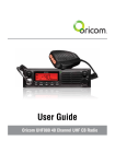
Oricom UHF050 40 Channel UHF CB Radio
Table of contents
Important Information
Please read before installing or operating your Oricom Radio
Safety Warning
Controls and Connectors
Installation of your Oricom UHF 050
Box Contents
Antenna Installation
DC Power
DIN Kit
Optional External Speaker
Operation
Dual Function buttons
Power ON / OFF
Squelch
To Select a Channel
To Select A CTCSS / DCS or 60Rx Receive channels
Transmitting
Busy Channel Lock (BCL)
To Transmit
Call Tone
CTCSS (Continuous Tone Coded Squelch System)
DCS (Digitally Coded Squelch)
Receive & Transmit Indicator
Time Out Timer (ToT)
Duplex Operation
Roger Beep (RGB)
Emergency Channel (EMG)
Priority Channel (PRI)
BEEP Tone (BPT)
Memory Scan
Priority Scan
LCD Display Controls
60 Rx channels
Factory Reset
Specifications
Frequency Table (Channel 1-20)
Frequency Table (Channel 21-40)
Warranty
Customer Support
4
4
5
6
8
8
8
9
9
9
10
10
10
10
10
10
11
11
11
12
12
12
13
13
13
15
15
15
16
16
17
17
17
18
19
20
21
22
23
3
Important information
Please read before installing or operating
your Oricom Radio
The operation of this radio in Australia and New Zealand is subject
to conditions in the following licenses. In Australia the ACMA Radio
communications (Citizen Band Radio Stations) and in New Zealand by MED
General User Radio License for Citizen Band Radio and operation is subject
to conditions contained in those licences.
Channels 5 and 35 (paired for Duplex repeaters) are reserved as emergency
channels and should be used only in an emergency. CTCSS and DCS will
not operate on these channels.
Channel 11 is a calling channel generally used to call others and channel
40 is the customary road vehicle channel.
Once contact is established on the calling channel, both stations should
move to another unused “SIMPLEX” channel to allow others to use the
calling channel.
Channels 22 and 23 are for Telemetry and Telecommand use, voice
communications are not allowed on these channels by law.
Channels marked Duplex are reserved for repeater use in some areas.
These are paired with higher channels as output/input (1/31, 2/32, etc.)
Check for local repeater activity before using these channels in Simplex
mode to avoid interference. Channels 9 and above are the best choices for
general use in Simplex mode. You can find more information about channels
and frequencies by visiting the Web site:
http://www.acma.gov.au
Note:
Refer to the “Channel Table” section of this Owner’s Manual for detailed
frequency listing.
4
Important information
Safety Warning
WARNING
NOTE:
Areas with potentially explosive atmospheres are often, but
not always clearly marked. They include fueling areas such
as below deck on boats; fuel or chemical transfer or storage
facilities; areas where the air contains chemicals or particles,
such as grain, dust, or metal powders; and any other area
where you would normally be advised to turn off your vehicle
engine.
Potentially Explosive Atmospheres
Turn your radio OFF when in any area with a potentially
explosive atmosphere. Sparks in such areas could cause an
explosion or fire resulting in injury or even death.
Blasting Caps and Areas
To avoid possible interference with blasting operations, turn
your radio OFF near electrical blasting caps or in a “blasting
area” or in areas posted: “Turn off the two way radio.” Obey all
signs and instructions.
Electromagnetic Interference/Compatibility
Nearly every electronic device is susceptible to electromagnetic
interference (EMI). To avoid the possibility of electromagnetic
interference and/or compatibility conflicts, turn off your radio
in any location where posted notices instruct you to do so such
as health care facilities.
5
Operation
Controls and Connectors
Front View
1
2
3
4 5
CTCSS
DCS
60RX
6
1.
2.
3.
4.
5.
6.
7.
8.
9.
10.
11.
12.
13.
14.
6
7
8
9
10
11
12 13
Rotary On / Off Switch and Volume Control
LCD Display
Rx / Tx Indicator
CTCSS / DCS, 60 Channel Rx Selector switch
Rotary squelch control
Microphone connector
Call- Call Button, Set- Set Button
M SC – Memory Scan, P SC – Priority Scan
DW – Dual Watch, BPT – Beep Tone
MEM – Memory Skip, RGB – Roger Beep
EMG – Emergency Channel, DPX – Duplex
PRI – Primary, BCL – Busy Channel Lock
BLT – Back light, DIM – DIM
Rotary Channel Button
14
Operation
Rear View
1
1.
2.
3.
2
3
Antenna Connection
3.5mm external jack for optional 8 ohm speaker
Power Supply Connection
Microphone
1.
2.
3.
4.
Push to talk switch (PTT)
Select Up
Select Down
Instant Channel
2
4
3
1
7
Installation of your Oricom UHF050
Box Contents
1 X UHF050 CB Radio
1 X Microphone
1 X DC Power cord with inline fuse
1 X Mounting bracket with mounting screws
1 X Microphone hanger
1 X DIN mounting kit
1 X User Guide
When installing your radio in your vehicle, check that during
installation you do not damage any wiring or vehicle components
that may be hidden around the mounting position.
If you are unsure about how to install your radio, we suggest
for optimum performance you have your radio professionally
installed by a UHF specialist or Auto electrician. When installing
the radio, avoid mounting it close to heaters or air conditioners.
Do not press the PTT or CALL button before installing the
antenna.
Antenna Installation
To obtain the best performance from your UHF050 it is important to obtain
a good quality antenna. You should purchase an antenna designed for the
477MHz frequency band.
1. Connect the antenna to the rear antenna socket using a PL259 coaxial
connector.
8
Installation of your Oricom UHF050
DC Power
The UHF050 is designed for 13.8V DC negative earth installations only.
1. Connect the negative (Black) DC power lead to the vehicle chassis or
directly to the vehicle battery negative terminal if preferred.
2. Connect the positive (Red) DC power lead via the in line fuse to a
suitable point in the vehicle fuse box or directly to the positive battery
terminal. When selecting a suitable point take into consideration if you
want your UHF 050 to be operational when the car ignition is off.
DIN Kit
The UHF050 can be installed using a optional DIN Kit - Part number; DIN050
for mounting in a vehicle dash board.
Optional External Speaker
Depending on the installation it may be necessary to use an external
speaker (not supplied) to give improved volume and clarity. This can be
plugged into the EXT –SPK socket on the rear of the unit.
9
Operation
Operation
Dual Function buttons
The dual function button (buttons 7 to 13) have two functions.
To use the primary function (printed on the button) just press the button. To
use the secondary function (printed above the button)
press and hold the button for 2 seconds.
Power ON / OFF
Rotate the power switch in a clockwise direction to turn the unit ON,
adjust the volume to a comfortable level. Rotate the Power Switch counter
clockwise until it click to turn off the power.
Squelch
To adjust the level of squelch use the rotary SQL control. Turning the control
clockwise reduces the amount of squelch, turning counter clockwise
increase the amount of squelch. To reduce the signals that you can hear,
increase the squelch, to hear more signals which may include weak signals
decrease the squelch.
To Select a Channel
To select a channel rotate the CH control clockwise or counter clockwise to
the desired channel.
To Select A CTCSS / DCS or 60Rx Receive channels
Press the CTCSS / DCS button once to obtain CTCSS channel select. Press
twice to obtain DCS channel select.
Press and hold the button for 2 seconds to obtain the 60Rx channels.
10
Operation
Transmitting
NOTE: Before transmitting on any channel, listen to check the channel
is not already in use.
Busy Channel Lock (BCL)
If you turn ON the BCL feature of the UHF050 you will be prevented from
accidentally transmitting while the channel is in use.
To Turn ON BCL
1. Press and hold the BCL button for 2 seconds, BCL will appear on the
LCD display.
To Turn OFF BCL
1. Press and hold the BCL button for 2 seconds, BCL will disappear from
the LCD display.
To Transmit
1. Select the channel you wish to use, please refer the Channel Reference
at the end of this user guide for a list of available channels and their use.
2. Press the PTT switch on the Mic
TIP: To ensure your voice is transmitted with the best clarity hold the
microphone 5 to 7 cm from your mouth, talk at a normal level, do not
shout.
11
Operation
Call Tone
A call tone alerts others on your channel that you want to talk.
Your radio has 5 call tones to choose from.
To select a call tone
1. Press and hold SET for 2 seconds.
2. Rotate the Channel button ( or press the Up / Down Select on the Mic)
to select the desired Call Tone.
To transmit a call tone
1. Pressing the call switch will cause a 3 second call tone to be
transmitted.
NOTE: Australian and New Zealand standards restrict tone calling to 3
seconds in any 60 second period.
CTCSS (Continuous Tone Coded Squelch System)
Your UHF050 has 38 CTCSS codes to minimise interference from other
users. You will only hear transmissions from users using the same code.
To select a CTCSS code
1. Press the CTCSS / DCS button, TSQ of will blink on the
LCD display.
2. Turn the Channel control to select the desired CTCSS code.
3. Press the CTCSS / DCS button twice to return to standby.
DCS (Digitally Coded Squelch)
Your UHF050 provides for 104 DCS codes. These are digitally coded squelch
codes which provide additional privacy.
To select a DCS code
1. Press the CTCSS / DCS button twice, DCS – of appears on the
12
LCD display.
Operation
2. Rotate the Channel button or press Up / Down Select on the Mic to
select the desired DCS channel code.
3. Press the CTCSS / DCS button once to return to standby.
Receive & Transmit Indicator
The LED indictor will illuminate green when the unit is receiving a signal,
when transmitting it will illuminate red. When in standby the LED is out.
Time Out Timer (ToT)
Australian and New Zealand standards require that if the PTT is pressed for
more than 3 minutes the unit must stop transmitting. The UHF050 is set to
stop transmitting after 2 minutes and 30 seconds of continous transmitting.
After that time the unit will stop transmitting and TOT will appear in the
display to indicate that the ToT has activated.
Duplex Operation
General
Your radio has a Repeater Access function to allow use of local Repeater stations
(if available in your area). Repeaters are shared radio system installed by
interested parties (clubs, local business etc.) that pick transmissions on specific
channels and re-transmit (or repeat) the received signal to another channel.
el 2
ann 32
Ch nnel
a
Ch
Repeater Station
Ch
an
ann nel 2
el 3
2
Ch
13
Operation
The Repeater Access function can be set (from channel 1 to 8) used by local
repeater stations. When activated, your radio will receive the Repeater on its
specific channel (all repeater outputs are on channel 1 to 8) but transmits to
the repeater channel 31 through 38.
e.g.
CH01 on Duplex mode will receive on CH01 but transmit on CH31
CH02 on Duplex mode will receive on CH01 but transmit on CH32.
CH and Number
Simplex mode Transmit/
reciever Frequency (MHz)
Duplex Mode transmit
Frequency(MHz)
1
476.425
477.175 CH31
2
476.450
477.200 CH32
3
476.475
477.225 CH33
4
476.500
477.250 CH34
5
476.525
477.275 CH35
6
476.550
477.300 CH36
7
476.575
477.325 CH37
8
476.600
477.350 CH38
To Turn Duplex (DPX) ON
1. Press and hold the DPX button for 2 seconds, DPX will appear on the
LCD display.
To Turn Duplex (DPX) OFF
1. Press and hold the DPX button for 2 seconds, the DPX will disappear
from the LCD display.
NOTE: For an up to date list of repeaters you can visit:
http://www.acma.gov.au
14
Operation
Roger Beep (RGB)
Roger beep emits a tone when you release the PTT switch.
To turn ON the roger beep
1. Press the RGB button for 2 seconds, the <note icon> appears in
the display.
To turn OFF the roger beep
1. Press the RGB button for 2 seconds, the <note icon> disappears from
the display.
Emergency Channel (EMG)
The EMG button gives instant access to emergency channels 5 and 35.
To access the emergency channel
1. Press the EMG button, Channel 5 I selected and displayed on the LCD.
2. If you press the EMG button a 2nd time the channel changes to 35.
3. If you pres the EMG button a 3rd time the unit return to the original
channel.
Priority Channel (PRI)
You can select a priority channel which is used during scanning functions
and can be accessed immediately via the INS button on the Microphone.
To Select the Primary Channel
1. Select the desired primary channel using the channel control, including
any CTCSS or DCS code.
2. Press the PRI button on the unit or press and hold the INS button on the
Microphone.
15
Operation
To switch to the primary Channel
1. Press the INS button on the Microphone.
BEEP Tone (BPT)
The Beep Tone emits a tone when you press any of the buttons on the
Microphone (except the PTT switch)
To Turn ON the BEEP Tone
1. Press and hold the BPT button for 2 seconds, BPT appears on the LCD
display.
To Turn OFF the BEEP Tone
1. Press and hold the BPT button for 2 seconds, the BPT disappears from
the LCD display.
Memory Scan
Initially All 40 channels are stored in memory, indicated by MEM next to the
channel on the LCD display. During a memory scan all channels in memory
are scanned for a signal.
To Remove or Add a channel to the memory
1. Select the channel you wish to add or remove from memory.
2. Press the MEM key to add or remove from memory, MEM will be
displayed on the LCD if the channel is in memory.
To start a Memory Scan
1. Press the M SC button, the scan will start, M-SC will be displayed on
the LCD display.
To stop a Memory Scan
1. Press the M SC button, the scan will stop, M-SC will disappear from
the LCD display.
16
Operation
Priority Scan
In a priority scan the selected priority channel is checked for every 5
memory channels.
To Start a Priority Scan
1. Press the P SC button for 2 seconds, the priority scan will start,
P-SC will be displayed on the LCD.
To Stop a Priority Scan
1. Press the P SC button for 2 seconds, the Priority Scan will stop, P-SC
will disappear from the LCD display.
LCD Display Controls
Display Backlight
You can select from two colour options for the LCD backlight. The two
options are Orange and Green.
To select the backlight colour (BLT)
1. Press the BLT button, the display will toggle between Orange and Green.
Display Brightness
You can reduce the brightness of the LCD backlight to be more comfortable
while driving at night.
To Dim the display
1. Press and hold the DIM button for 2 seconds, the display will toggle
between normal and DIM brightness levels.
60 Rx channels
The UHF050 has 60 receive only channels which can be programmed from
450MHz to 512MHz in steps of 12.5KHz.
17
Operation
To program a receive channel.
1. Press and hold the 60Rx button for 2 seconds, the display will show
channel 41. to select a different channel use the Channel control.
2. Press the PRI button, the 450 in the frequency display will start
blinking, use the Channel control to select the desired MHz.
3. Press the PRI button, the 000 in the frequency display will start
blinking, use the Channel control to select the desired KHz.
4. Press MEM, the frequency is stored to that channel.
Factory Reset
Should it be necessary you can return all the UHF050 settings to the factory
defaults to do this.
1. Switch the unit OFF.
2. Press and hold the CALL button.
3. While still holding the Call button, turn the power switch to ON, this will
reset the factory defaults.
18
Specifications
Specifications
Available Tx Channels
Power Output
CTCSS Sub Channels
DCS Codes
Receive only channel Range
Input Voltage
In-line fuse rating
Antenna Impedance
38
5 Watts
38 per channel
104 per channel
450MHz to 512Mhz in 12.5KHz steps
10VDC to 15VDC
2 Amps
50 Ohms
19
Specifications
Frequency Table (Channel 1-20)
20
Channel
Frequency (MHz)
Usage
1
476.425
Duplex RX/Simplex
2
476.45
Duplex RX/Simplex
3
476.475
Duplex RX/Simplex
4
476.5
Duplex RX/Simplex
5
476.525
Emergency
6
476.55
Duplex RX/Simplex
7
476.575
Duplex RX/Simplex
8
476.6
Duplex RX/Simplex
9
476.625
Simplex
10
476.65
Simplex
11
476.675
Simplex (Calling channel)
12
476.7
Simplex
13
476.725
Simplex
14
476.75
Simplex
15
476.775
Simplex
16
476.8
Simplex
17
476.825
Simplex
18
476.85
Simplex
19
476.875
Simplex
20
476.9
Simplex
Specifications
Frequency Table (Channel 21-40)
Channel
Frequency (MHz)
Usage
21
476.925
Simplex
22
476.95
No Use
23
476.975
No Use
24
477
Simplex
25
477.025
Simplex
26
477.05
Simplex
27
477.075
Simplex
28
477.1
Simplex
29
477.125
Simplex
30
477.15
Simplex
31
477.175
Duplex TX/Simplex
32
477.2
Duplex TX/Simplex
33
477.225
Duplex TX/Simplex
34
477.25
Duplex TX/Simplex
35
477.275
Emergency
36
477.3
Duplex TX/Simplex
37
477.325
Duplex TX/Simplex
38
477.35
Duplex TX/Simplex
39
477.375
Simplex
40
477.4
Simplex
21
Warranty and Customer Support
Warranty
(a) Warranty. Oricom International Pty Ltd (Oricom) warrants that the product is free
from defects in materials and workmanship for a period of 36 months effective from
the date of purchase. This warranty in no way affects your statutory warranty under
the Trade Practices Act 1974 or any other similar legislation. It is important that
you read the Warranty Card as it contains full and additional details of the warranty,
limitation of warranty and conditions for receiving the warranty services during the
warranty period. The Warranty Card is located in the package.
(b) Exclusion and limitation of liability. Oricom will not be in breach of a warranty or
condition expressly stated in this User Guide or the Warranty Card or implied by the
Trade Practices Act and excludes any liability arising under any statutory or common
law for damages or any other remedy if the damage occurs as a result of:
(i) Failure by you to follow the instructions in the User Guide for the installation and
proper functioning of the product;
(ii) Negligence on your part or misuse by you of the product;
(iii) Any un-controlled external cause to the phone not functioning including but not
limited to electricity failure, lighting, over voltage;
(iv) Non adherence by you to the warnings in the User Guide and the wUser Guide
generally; and
(v) Modification to the product or services carried out to the product by anyone other
than Oricom or on Oricom’s behalf.
Oricom will not be liable for consequential losses including loss of profits arising
from a cause of action in contract, tort or any other statutory or common law
(except where a statute or any law prohibits this exclusion).
The warranty does not extend to damage caused by misuse, negligence, excessive
voltage, faults on the telephone line or lightning. This warranty in no way affects
your statutory rights. Full details of the warranty are contained in the enclosed
warranty card.
22
Warranty and Customer Support
Customer Support
If you feel this product is not working correctly please consult the user guide and
ensure that you are using the product in accordance with the instructions.
To order spare parts additional radio, replacement batteries and in case of any
technical issues you may have with the product please consult our website for
further information or send us an email for a prompt response to your enquiry.
In the unlikely event of a fault developing, please contact us for assistance. If the
product is then found to be faulty you will be asked to return it directly to us with a
copy of the purchase receipt.
23
Australia
Oricom International Pty Ltd
Locked Bag 658
South Windsor, NSW 2756
Customer Support
Email: [email protected]
Web: Australia www.oricom.com.au
New Zealand www.oricom.co.nz
Phone: (02) 4574 8888
Fax: (02) 4574 8898