1
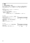
GENERAL DESCRIPTION
The Omega PRG-501 and PRG501 Series Pressure Regulators have an advanced design
consisting of a precision measurement capsule and a high gain servo amplifier to achieve
high performance. The regulator can be used in a ‘dead end’ application and will exhaust
whenever the setpoint is lowered. Changes in supply pressure have a minimal effect on
the regulation accuracy. The regulator can be panel or pipe mounted. These regulators are
unaffected by vibration and mounting position. A set point locknut is provided.
The PRG101 has two ¼ NPT gauge ports available for mounting OMEGA® pressure
gauges for local indication. The PRG501 is ideal for having a dial gauge reading when
the unit is panel mounted. The dial gauge would be external to the panel.
The PRG101 regulators are available in the following pressure ranges:
Model No.
PRG101-120
PRG101-60
PRG101-25
Adjustable Range
2-120 PSIG
2-60 PSIG
2-25 PSIG
The PRG501 regulators are available in the following pressure ranges:
Model No.
PRG501-120
PRG501-60
PRG501-30
PRG501-X15
Adjustable Range
2-120 PSIG
2-60 PSIG
2-30 PSIG
3-15 PSIG
OPERATION
The PRG101 and PRG501 are precision pressure regulators, normally used with
compressed air. The operation has been specifically designed for zero flow ‘dead end’
service, but can provide large air flows up to 5L/sec (10scfm) when required. It maintains
a highly stable outlet pressure against variation in supply pressure, flow, temperature and
vibration. These instruments use small quantities of air for operation (0.5-2 litres/minute)
and can be set to a minimum below 0.14 bar (2psi). Tight shut off is not possible.
BASIC MECHANISM
The units use a piston to control a high gain pneumatic two-stage servo system. When
increasing the regulated pressure the handwheel is turned clockwise, forcing the
measuring capsule/piston assembly downward. This pushes the pilot diaphragm and
control diaphragm downward. As a result, the main valve opens and the supply pressure
enters the regulator. The resulting pressure change causes the measuring capsule to
compress. This compression causes the pilot diaphragm and the control diaphragm to
move upward, which then shuts the main valve.
When decreasing the regulated pressure, the handwheel is turned counterclockwise,
forcing the measuring capsule/piston assembly upward. This allows the pilot diaphragm
and control diaphragm to move upward. As a result, the relief valve opens and air is
exhausted through the vent. The resulting pressure drops causes the measuring capsule to
expand. This expansion causes the pilot diaphragm and control diaphragm to move down,
which then shuts the relief valve.
To maintain a state of equilibrium, the action of the measuring capsule as described
above ensures a precise constant pressure regulation. Air is bled at a constant rate through
the bleed orifice so that a very small movement of the pilot valve induces a substantial
pilot pressure change, which creates a high servo amplification.
INSTALLATION
Mounting
The PRG101 is usually panel mounted into a minimum 11.5mm hole. Direct pipe
mounting is also possible. To install on a panel remove the knob (grub screw) tension nut
and mounting nut. Insert into the panel and replace the nuts and knob. The mounting nut
should be retightened to a torque of 5Nm; set the tension nut to give adequate friction for
the desired service. It is not necessary to remove the locknuts for installation; these may
be reset if required to give a maximum pressure below the factory setting.
Pneumatics
All pneumatics ports are threaded ¼” NPT. Two gauge ports may be used as required,
and are supplied sealed with pipe plugs.
The following installation precautions are ESSENTIAL:
Air supply- This can be between limits of 0.2 bar (3 psi) above the maximum required
outlet pressure and 10 bar (150psi). The air supply must be filtered to 25 micron, with oil
content below 1ppm and dew point at least -10˚C below lowest ambient temperature.
Filtering and oil removal are vital for long life.
Pipe Fitting – Fit appropriate pipe fittings for the pipe sizes required. DO NOT USE
PTFE TAPE. Thread sealing can be easily achieved with loctite hydraulic seal or similar
anaerobic seals.
Pipe sizes – 6mm plastic tubes are commonly used, but increase to 8 or 10mm is
desirable if long pipe runs of high flows are present. Plastic tubes (e.g. nylon) are
convenient and clean.
HEALTH AND SAFETY
The units are simple pressure control instruments and present few safety hazards.
Installation should be in accordance with BS6739 or other relevant national standards.
Compressed air can produce accidents if not correctly used and the user is urged to
adhere to established compressed air safety standard.
These instruments contain no substance which presents hazards in normal use. The
measuring capsule is constructed of beryllium copper, which can present disposal
hazards; if a satisfactory disposal procedure is not available, scrap instruments should be
returned to the factory.
DIMENSION DETAILS
M a x . p re s s u re
s to p lo c k n u ts
T e n s io n n u t
4 3 .5 R E F
L o c knut fo r
m o u n tin g
B le e d s c re w
E xhaus t
s lo ts
69 REF
O u tle t
p o rt
I n le t p o rt
1 3 .6 R E F
54 REF
I n le t p o rt
1 /4 ” N P T
54 REF
Ø 1 1 re q u ire d f o r p a n e l m o u n tin g
G aug e
p o rt 1 /4 ”
NP T
M1846-09/02