1
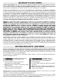
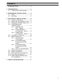
User’s Guide
omega.com
®
®
http://www.omega.com
e-mail: [email protected]
CN3440 SERIES
Universal Temperature & Process
Controllers
Installation Guide
WARRANTY/DISCLAIMER
OMEGA ENGINEERING, INC. warrants this unit to be free of defects in materials and workmanship for a
period of 37 months from date of purchase. OMEGA Warranty adds an additional one (1) month
grace period to the normal three (3) year product warranty to cover handling and shipping time.
This ensures that OMEGA’s customers receive maximum coverage on each product.
If the unit malfunctions, it must be returned to the factory for evaluation. OMEGA’s
Customer Service Department will issue an Authorized Return (AR) number immediately upon phone
or written request. Upon examination by OMEGA, if the unit is found to be defective, it will be repaired
or replaced at no charge. OMEGA’s WARRANTY does not apply to defects resulting from any action of
the purchaser, including but not limited to mishandling, improper interfacing, operation outside of
design limits, improper repair, or unauthorized modification. This WARRANTY is VOID if the unit shows
evidence of having been tampered with or shows evidence of having been damaged as a result of
excessive corrosion; or current, heat, moisture or vibration; improper specification; misapplication;
misuse or other operating conditions outside of OMEGA’s control. Components which wear are not
warranted, including but not limited tocontact points, fuses, and triacs.
OMEGA is pleased to offer suggestions on the use of its various products. However,
OMEGA neither assumes responsibility for any omissions or errors nor assumes
liability for any damages that result from the use of its products in accordance with information
provided by OMEGA, either verbal or written. OMEGA warrants only that the parts
manufactured by it will be as specified and free of defects. OMEGA MAKES NO OTHER
WARRANTIES OR REPRESENTATIONS OF ANY KIND WHATSOEVER, EXPRESS OR IMPLIED,
EXCEPT THAT OF TITLE, AND ALL IMPLIED WARRANTIES INCLUDING ANY WARRANTY OF
MERCHANTABILITY AND FITNESS FOR A PARTICULAR PURPOSE ARE HEREBY DISCLAIMED.
LIMITATION OF LIABILITY: The remedies of purchaser set forth herein are exclusive, and the
total liability of OMEGA with respect to this order, whether based on contract, warranty,
negligence, indemnification, strict liability or otherwise, shall not exceed the purchase price of
the component upon which liability is based. In no event shall OMEGA be liable for
consequential, incidental or special damages.
CONDITIONS: Equipment sold by OMEGA is not intended to be used, nor shall it be used: (1) as a
“Basic Component” under 10 CFR 21 (NRC), used in or with any nuclear installation or activity; or (2) in
medical applications or used on humans. Should any Product(s) be used in or with any nuclear
installation or activity, medical application, used on humans, or misused in any way, OMEGA assumes
no responsibility as set forth in our basic WARRANTY / DISCLAIMER language, and, additionally,
purchaser will indemnify OMEGA and hold OMEGA harmless from any liability or damage whatsoever
arising out of the use of the Product(s) in such a manner.
RETURN REQUESTS / INQUIRIES
Direct all warranty and repair requests/inquiries to the OMEGA Customer Service Department.
BEFORE RETURNING ANY PRODUCT(S) TO OMEGA, PURCHASER MUST OBTAIN AN AUTHORIZED
RETURN (AR) NUMBER FROM OMEGA’S CUSTOMER SERVICE DEPARTMENT (IN ORDER TO AVOID
PROCESSING DELAYS). The assigned AR number should then be marked on the outside of the
return package and on any correspondence.
The purchaser is responsible for shipping charges, freight, insurance and proper packaging to
prevent breakage in transit.
FOR WARRANTY RETURNS, please have the
following information available BEFORE
contacting OMEGA:
1. Purchase Order number under which
the product was PURCHASED,
2. Model and serial number of the product under
warranty, and
3. Repair instructions and/or specific
problems relative to the product.
FOR NON-WARRANTY REPAIRS, consult
OMEGA for current repair charges. Have the
following information available BEFORE
contacting OMEGA:
1. Purchase Order number to cover the COST of
the repair,
2. Model and serial number of the product, and
3. Repair instructions and/or specific problems
relative to the product.
OMEGA’s policy is to make running changes, not model changes, whenever an improvement is possible.
This affords our customers the latest in technology and engineering.
OMEGA is a registered trademark of OMEGA ENGINEERING, INC.
© Copyright 1998 OMEGA ENGINEERING, INC. All rights reserved. This document may not be copied,
photocopied, reproduced, translated, or reduced to any electronic medium or machine-readable form, in
whole or in part, without the prior written consent of OMEGA ENGINEERING, INC.
CONTENTS
1 INTRODUCTION .................................. 2
2 PREPARATION .................................... 3
2.1 Checking the Code Number ......... 3
3 MECHANICAL INSTALLATION .......... 4
3.1 Siting .......................................... 4
3.2 Mounting ...................................... 5
4 ELECTRICAL INSTALLATION ............ 6
4.1 Access to Terminals ..................... 6
4.2 Setting the Input Selector Links ... 6
4.3 Setting the Isolated Output Link ... 6
4.4 Cable Glands and
Conduit Fixings ............................ 8
4.4.1 Cable Glands
(IEC – 20mm) ................... 8
4.4.2 Conduit Adaptors
(N. American – 0.5in) ........ 8
4.4.3 Cable Glands
(N. American – 0.5in) ........ 9
4.5 Connections Summary ............... 10
4.6 Input Connections ...................... 12
4.6.1 Thermocouple
(THC) Inputs ................... 12
4.6.2 3-lead Resistance
Thermometer (RTD)
Inputs .............................. 12
4.6.3 2-lead Resistance
Thermometer (RTD)
Inputs .............................. 12
4.6.4 Links for Unused Inputs .. 12
4.7 Output Connections ................... 14
4.8 Relay Connections ..................... 14
4.9 Motorized Valve Connections .... 14
4.10 Logic Input Connections ............ 15
4.11 Power Supply Selection and
AC Connections ......................... 16
5 INSTALLATION RECORD ................. 17
1
1
INTRODUCTION
The instrument documentation is shown in Fig. 1.1. The Standard Manuals, including the
specification sheet, are supplied with all instruments. The Modbus Supplement is supplied with
instruments configured for Modbus Serial Communication.
This manual includes an Installation Record which should be completed as a log of the electrical
installation. The record is useful when carrying out initial instrument programming and can be
retained for future reference.
INSTALLATION
Product Identification
Siting
Mounting
Electrical Connections
Installation Record
PROGRAMMING
MODBUS (RTU).
Basic Config. Level
Operating Level
Serial Adaptors
Serial Connections
Programming Page
Simple Fault-Finding
MODBUS Registers
OPERATION
Setting Up
Displays & Controls
Advanced Config. Level
Standard Manuals
Fig. 1.1 Documentation
2
MODBUS Supplement
2
2.1
PREPARATION
Checking the Code Number – Fig. 2.1
XXXX / X X X X X X X X
Code Number Label
Fig. 2.1 Location of Code Number Label
3
3
MECHANICAL INSTALLATION
EC Directive 89/336/EEC
In order to meet the requirements of the
EC Directive 89/336/EEC for EMC
regulations, this product must not be used
in a non-industrial environment.
3.1
Siting – Figs. 3.1 and 3.2
Minimum
55°C
Max.
0°C
Min.
A – Within Temperature Limits
0 to 90% RH
Sensor
A – Close to Sensor
B – Within Humidity Limits
IP66/
NEMA4X
B – At Eye-level Location
C – Within Protection Rating Limits
+
C – Avoid Vibration
Fig. 3.1 General Requirements
Caution. Select a location
away from strong electrical and
magnetic fields. If these cannot be
avoided, particularly in applications
where ‘walkie talkies’ are used,
connect using screened cables
within earthed metal conduit.
D – Use Screened Cables
Fig. 3.2 Environmental Requirements
4
3
3.2
MECHANICAL INSTALLATION…
Mounting – Figs. 3.3 and 3.4
The instrument is designed for wall-/pipe-mounting – see Fig. 3.4. Overall dimensions are
shown in Fig. 3.3.
Dimensions in inches (mm)
1.65
(42)
Fixing Centres
2.68 (68)
6.3 (160)
8.43
(214)
9.84
(250)
2.72 (69)
7.9 (200)
Fixing Centres
Allowance for
Cable Bends
9.13
(232)
23/8 (61) O.D. Vertical or
Horizontal Post
Fixing Holes
(x3) 0.25 (6.5) Dia
Fig. 3.3 Overall Dimensions
2 Drill suitable
holes
Position ‘U’ bolts on pipe 1
Position plates over ‘U’ bolts
2
Pipe Mounting Kit
1
Mark fixing
centres
(see Fig. 3.3)
3 Secure plates
3
Fix instrument to
wall using
suitable fixing
4 Secure transmitter to mounting plate
Fig. 3.4 Wall-/Pipe-mounting Details
5
4
ELECTRICAL INSTALLATION
Warning. Before making any
connections, ensure that the power
supply, any high voltage-operated control
circuits and high common mode voltages
are switched off.
•
•
Note.
Always route signal leads and power
cables separately, preferably in
earthed metal conduit.
It is strongly recommended that
screened cable is used for signal
inputs and relay connections. Connect
the screen to the ground stud.
Information. Use cable appropriate
for the load currents. The terminals accept
cables up 12AWG (2.5mm2).
4.1
Access to Terminals – Fig. 4.1
For access to terminals – refer to Fig. 4.1,
steps 1 to 3.
4.2 Setting
the
Selector Links – Fig. 4.2A
Input
Plug-in links on the microprocessor p.c.b. are
positioned according to the type of Process
Variable Input, Remote Set Point Input and
Valve Position Feedback Inputs used.
Remove the instrument front panel – see
Fig. 4.1, steps 1 to 6.
Referring to Fig. 4.2A, set the link positions
for the input type required.
4.3 Setting
the
Output Link – Fig. 4.2B
Isolated
A plug-in link (PL7) on the microprocessor
p.c.b. is positioned according to the isolated
output
required,
either
a
current
proportioning control output (programmable
in range 0 to 20mA) or a 12V logic output
(minimum load 400Ω). Referring to Fig. 4.2B
– steps 1 and 2, set the link for the output
type required.
To use a 12V logic output, the control type
must be set to Time Proportioning Control –
see Fig. 3.1 of the Programming Guide.
6 Remove front
5 Remove cap
and screw
panel
1 slide
down
2Pull out
4 Remove front
slightly…
panel screws
2
…and
slide off
3 Slacken captive screws and
remove protection cover
Fig. 4.1 Access to Terminals and Processor Board
6
4
ELECTRICAL INSTALLATION…
1
Identify Link PL7
2
Set links for output type required
PL7
1
Logic Output
PL7
1
or
Analog Output
B – Isolated Output Types
8
5
4
5
4
4
8
PL2
PL3
1
5
4
4
1
PL3
5
8
PL3
5
4
5
8
PL2
1
8
1
6
7
6
7
12
1
PL3
Position
Feedback
Input
1
8
PL2
1
7
6
7
12
1
PL1
12
PL1
2-wire
Transmitter
Input
1
V
PL2
Remote
Set Point
Input
6
PL1
R, mV,
THC & RTD
1
mA
PL1
12
PL1
Process
Variable
Input
A – Input Types
Fig. 4.2 Setting the Selector Links
7
…4
ELECTRICAL INSTALLATION
4.4 Cable
and Conduit Fixings
Glands
4.4.1 Cable
(IEC – 20mm) – Fig. 4.3
Glands
4.4.2 Conduit
Adaptors
(N. American – 0.5in) – Fig. 4.4
•
•
•
•
'O'-Ring
Warning.
Rigid conduit must NOT be fitted to the
controller.
Controller adaptors must incorporate
a face seal.
Torque settings for the hubs and outer
nuts on the specified adaptors is 20ft.
lbs minimum, 25ft. lbs. maximum.
Information.
Suitable adaptors for controller
(mandatory for FM installations):
APPLETON
ST-50 PLUS STG-50 or STB-50
PLUS STG-50.
Reusable ONLY with replacement
ferrule STF-50.
O.Z. GEDNEY
4Q-50, 4Q50T or 4Q-50TG.
Alternative
Face Seal
Fig. 4.3 Cable Gland
(Supplied as standard)
Face
Seal
Seal
(Present
in O.Z.
Gedney
Fittings)
Outer Nut
Fig. 4.4 Conduit Adaptors
8
Hub
Ferrule
4
ELECTRICAL INSTALLATION…
4.4.3 Cable
Glands
(N. American – 0.5in) – Fig. 4.5
•
•
•
•
•
Warning.
Controller glands must be fitted with a
face seal.
Torque settings (hubs only) – 20ft. lbs
minimum, 25ft. lbs. maximum.
Outer nuts – hand tight plus a half turn
only.
Information.
Suitable Cable Glands: (mandatory for
FM installations):
O.Z. GEDNEY
SR-50-375 or SR-504
APPLETON
CG 3150 or CG-3150S (and STG50 sealing ring).
THOMAS & BETTS
2521.
When fitting cable glands to the
controller, start with an outer gland
and also temporarily fit a gland at the
opposite end, to aid location of the
transmitter gland plate. Fit and tighten
glands consecutively from initial
gland.
Alternative
Face Seal
Face
Seal
Hub
Fittings
vary
slightly
for
different
makes
Illustration
typical for
O.Z.Gedney
Outer Nut
Fig. 4.5 Cable Glands
9
…4
ELECTRICAL INSTALLATION
4.5
Connections Summary – Fig. 4.6
Information.
Input impedances:
Low voltage(mV) >10MΩ
Voltage >10MΩ
Current 10Ω.
Relay 1
Relay 3
Process Variable Input
Remote Set Point Input
Relay 2
Power
Supply
3 4 5
6 7 8 9 10 11
12 13 14 15 16 17
1 2
18 19 20 21 22 23 24 25 26
MODBUS (RTU)
(if option fitted)
27 28 29 30 31 32
Control Output
Logic Input
Position Feedback Input
Retransmission Output
Fig. 4.6 Terminal Block Identification
10
4
ELECTRICAL INSTALLATION…
Terminal Number
1
2
AC Supply
L
24V, 115V or 230V a.c.
N
3
4
5
N/O
C
N/C
Relay 1 Output
– see Fig. 4.17
Motorized Valve Control Relay (open)
– see Fig. 4.19A
6
7
8
N/O
C
N/C
Relay 2 Output
– see Fig. 4.17
Motorized Valve Control Relay (close)
– see Fig. 4.19A
9
10
11
N/O
C
N/C
Relay 3 Output
– see Fig. 4.17
Alarm Relays
12
13
14
3rd lead/2-wire TX
Input 1+
Input 1–
Process Variable Input
– see Figs. 4.7 to 4.9,
4.12 and 4.14
15
16
17
3rd lead
Input 2+
Input 2–
Remote Set Point Input – see Figs. 4.7 to 4.12 and 4.14
18
19
20
21
22
Tx+
Tx–
Common
Rx+
Rx–
23
24
+
–
Retransmission Output/Cool Output – see Fig. 4.15
25
26
+
–
Current Proportioning Control Output/Heat Output Fig. 4.15
or 12V Logic Control Output Fig. 4.16
27
28
29
3rd lead
Input 3+
Input 3–
Position Feedback Input – see Figs. 4.18 , 4.19A and 4.19B
30
31
32
– see Fig. 4.22
or
2-wire Tx Power Supply
– see Fig. 4.13
RS 485 Modbus Serial Communications Option 1 only – see
Modbus (RTU) Communications Supplement
Logic Input 1 – see Figs. 4.20 and 4.21
Logic Input 2 – see Figs. 4.20 and 4.21
Common
Table 4.1 Electrical Connections
11
…4
ELECTRICAL INSTALLATION
4.6
Input Connections
Make connections to each input, as shown in Figs 4.4 to 4.14, first removing any factory-fitted
wire links not required.
4.6.1
Thermocouple (THC) Inputs – Fig. 4.7
Note. Automatic Cold Junction Compensation (ACJC) is active when an input is
programmed for use with thermocouples. Use the correct compensating cable between the
THC and the terminals – see Table 4.2.
If an external fixed cold junction is used, the connections to the instrument must be made
with copper cable. The input must be programmed for mV input signals and the appropriate
THC linearizer selected – see Sections 4.5 and 4.6 of the Programming Guide.
Type of
Thermocouple
Ni-Cr/Ni-Al (K)
Nicrisil/Nisil ( N)
Pt/Pt-Rh (R and S)
Cu/Cu-Ni (T)
Fe/Con (J)
Compensating Cable
BS1843
+ Brown
– Blue
Case Red
+ Orange
– Blue
Case Orange
+ White
– Blue
Case Green
+ White
– Blue
Case Blue
+ Yellow
– Blue
Case Black
ANSI
MC 96.1
+ Yellow
– Red
Case Yellow
+ Orange
– Red
Case Orange
+ Black
– Red
Case Green
+ Blue
– Red
Case Blue
+ White
– Red
Case Black
DIN
43714
+ Red
– Green
Case Green
—
+ Red
– White
Case White
+ Red
– Brown
Case Brown
+ Red
– Blue
Case Blue
BS4937
Part No.30
+ Green
– White
Case Green *
+ Pink
– White
Case Pink *
+ Orange
– White
Case Orange *
+ Brown
– White
Case Brown *
+ Black
– White
Case Black *
* Case Blue for intrinsically safe circuits
Fe/Con (DIN 43710)
—
—
DIN 43710
+ Blue/red
– Blue
Case Blue
—
Table 4.2 Thermocouple Compensating Cables
4.6.2
3-lead Resistance Thermometer (RTD) Inputs – Fig. 4.8
The three leads must have equal resistance, not exceeding 50Ω each.
4.6.3
2-lead Resistance Thermometer (RTD) Inputs – Fig. 4.9
If long leads are necessary it is preferable to use a 3-lead RTD. If the RTD is to be used in a
hazardous area a 3-lead RTD must be used.
4.6.4
Links for Unused Inputs
To reduce susceptibility to electro-magnetic interference, ensure that the three terminals on
each unused input are shorted together with sleeved wire links.
12
4
% ^ &
@ £ $
Sleeved
Link
+
–
Fig. 4.7 Thermocouple Input Connections
–
Fig. 4.12 Current Input Connections
@ £$
% ^&
@ £$
Red White
@ £$
Sleeved
Link
+
Remote Set Point
Process Variable
% ^&
Remote Set Point
Process Variable
+
Remote Set Point
Process Variable
ELECTRICAL INSTALLATION…
Red
Tx
–
Fig. 4.13 2-wire Transmitter
Power Supply Input Connections
Fig. 4.8 3-lead Resistance
Thermometer Input Connections
Remote Set Point
Process Variable
% ^ &
@ £ $
Sleeved
Link
Sleeved
Link
–
Fig. 4.14 Voltage Input Connections
Red
White
Fig. 4.9 2-lead Resistance
Thermometer Input Connections
% ^&
Retransmission O/P
or 'Cool' Analogue O/P
in Heat/Cool
23 24
25 26
Current Proportioning
Control Output
+
Remote Set Point
% ^&
@ £$
+
Remote Set Point
Process Variable
Remote Set Point
% ^&
Sleeved Link
Fig. 4.11 2-lead Resistance
Remote Set Point Input Connections
Fig. 4.15 Current Proportioning Control
and Retransmission Output Connections
12V Logic Output for ON/OFF
or Time-proportioning Control
25 26
+
Fig. 4.10 3-lead Resistance
Remote Set Point Input Connections
–
–
Fig. 4.16 Logic Control Output Connections
13
…4
ELECTRICAL INSTALLATION
4.7
Output Connections
3 4 5 67 8
Make connections as shown in Figs 4.15 and
4.16.
4.8
Relay Connections – Fig. 4.17
For relay functions refer to the following
table.
Relay 1
Relay 2
Relay 3
On/Off Control
✓
—
—
Time Prop.(Heat)
✓
—
—
Time Prop.(Cool)
—
✓
—
Motorized Valve
Open
Close
—
Alarm
✓
✓
✓
9 0 !
6 7 8
3 4 5
Relay 3
Relay 2
Relay 1
Motorized
Valve Drive
100% 0%
Valve
Positioner
Power
Supply
100%
(L) L
0%
N (N)
Link
27 28 29
A – Standard Feedback Slidewire
Configuration
27 28 29
Normally Open
Common
Normally Closed
Link
Fig. 4.17 Relay Connections
0%
4.9 Motorized
Valve
Connections – Figs. 4.18 and 4.19
+
–
Motorized Valve
Drive
Fig. 4.18 Motorized Valve Feedback
Connections (using V, I or mV feedback)
14
Motorized Valve Drive
B – Alternative Feedback Slidewire
Configuration
27 28 29
Sleeved Link
100%
Note. Link must be connected
at the motorized valve drive
terminals and not the Controller
terminals.
Fig. 4.19 Motorized Valve Connections
(using feedback slidewire)
4
4.10
ELECTRICAL INSTALLATION…
Logic Input Connections – Figs. 4.20 and 4.21
Each logic input can be programmed to perform one of a number of functions – see Section
3.10 of the Programming Guide.
Auto/
Local/Remote Dual Set Point
Selection
Manual
Set Point
Selection
Selection
Fixed Dual
Local
Automatic
Set Point 2
Alarm
Acknowledgement
* Alarm
Acknowledge
5V
Logic switching
0V
Manual
Fixed Dual
Set Point 1
Remote
or Dual
* Leading 'edge-triggered'
(minimum duration 200ms)
30 31 32
30 Logic Input 1
31 Logic Input 2
Automatic
Local
Manual
Remote (Dual)
Fixed Dual Set Point 2
Fixed Dual Set Point 1
Alarm Ack.
Note. Only one function may be
performed by each input at any one time.
32 Common
Fig. 4.20 Standard Logic Input Functions
Hold
(Soak)
* Profile
Reset
* Skip
Segment
5V
Logic switching
0V
* Leading 'edge-triggered'
(minimum duration 200ms)
Start
Profile
30 31 32
P–Strt
P–rSEt
P–SKIP
Hold/ (Soak)
Start Profile
Profile Reset
Skip Current Segment
30 Logic Input 1
31 Logic Input 2
Note. Only one function may be
performed by each input at any one time.
32 Common
Fig. 4.21 Additional Logic Input Functions for Profile Selection
15
…4
4.11
ELECTRICAL INSTALLATION
Power Supply Selection and AC Connections – Fig. 4.22
115V
115
1
Digit 7
Code Label
C31 x x x x x x x x x
2
3
Selector not Fitted (24V AC)
230
230V
A – Selecting the Supply Voltage
115
Information.
Fuse Rating - 5A Type T
Neutral
Line
Remove plug to
make connection
Fuse
Ground
B – Power Supply Connections
Fig. 4.22 Power Supply Selection and AC Connections
16
4
ELECTRICAL INSTALLATION…
Connection/Terminal Number
1
L
2
N
3
NO
4
C
5
NC
6
NO
7
C
8
NC
9
NO
Power Supply
Power Supply (Tick Box)
230V AC
24V AC
115V AC
Output Type:
Relay 1 Output
Output Function:
Output Type:
Relay 2 Output
Output Function:
Output Type:
Relay 3 Output
10 C
Output Function:
11
NC
Link Positions (Tick Box)
12 3rd
Process Variable
Input
13 +
14 –
mA
mV/THC/RTD V
2-wire Tx
Link Positions (Tick Box)
15 3rd
Remote Set Point
Input
16 +
17 –
mA
mV/THC/RTD
18 Tx+
Modbus Serial
Communications
Option 1 only
V
Termination Resistors (Tick Box)
19 Tx–
Linked-out
20
Common
21 Rx+
22 Rx–
Retransmission
Output
Linked-in
23 +
Output Type:
24 –
Output Function:
17
…4
ELECTRICAL INSTALLATION
Connection/Terminal Number
Link Positions (Tick Box)
25 +
Control Output
26 –
Analog Output Logic Output
27 3rd
Position Feedback
Input
28 +
29 –
Logic Input 1
30
Logic Input 2
31
Common
32
18
Link Positions (Tick Box)
mA
mV
R
V
NOTES
19
…NOTES
20
omega.com
®
®
OMEGAnet ® On-Line Service
http://www.omega.com
Internet e-mail
[email protected]
Servicing North America:
USA:
ISO 9001 Certified
Canada:
One Omega Drive, Box 4047
Stamford, CT 06907-0047
Tel: (203) 359-1660
e-mail: [email protected]
976 Bergar
Laval (Quebec) H7L 5A1
Tel: (514) 856-6928
e-mail: [email protected]
FAX: (203) 359-7700
FAX: (514) 856-6886
For immediate technical or application assistance:
USA and Canada: Sales Service: 1-800-826-6342 / 1-800-TC-OMEGASM
Customer Service: 1-800-622-2378 / 1-800-622-BESTSM
Engineering Service: 1-800-872-9436 / 1-800-USA-WHENSM
TELEX: 996404 EASYLINK: 62968934 CABLE: OMEGA
Mexico and
Latin America:
Tel: (95) 800-826-6342
En Espan˜ol: (95) 203-359-7803
FAX: (95) 203-359-7807
e-mail: [email protected]
Servicing Europe:
Benelux:
Postbus 8034, 1180 LA Amstelveen, The Netherlands
Tel: (31) 20 6418405
FAX: (31) 20 6434643
Toll Free in Benelux: 0800 0993344
e-mail: [email protected]
Czech Republic:
ul. Rude armady 1868, 733 01 Karvina-Hranice
Tel: 420 (69) 6311899
FAX: 420 (69) 6311114
Toll Free: 0800-1-66342
e-mail: [email protected]
France:
9, rue Denis Papin, 78190 Trappes
Tel: (33) 130-621-400
Toll Free in France: 0800-4-06342
e-mail: [email protected]
FAX: (33) 130-699-120
Germany/Austria: Daimlerstrasse 26, D-75392 Deckenpfronn, Germany
Tel: 49 (07056) 3017
Toll Free in Germany: 0130 11 21 66
e-mail: [email protected]
FAX: 49 (07056) 8540
United Kingdom: One Omega Drive, River Bend Technology Centre
ISO 9002 Certified
Northbank, Irlam, Manchester
M44 5EX, United Kingdom
Tel: 44 (161) 777-6611
FAX: 44 (161) 777-6622
Toll Free in the United Kingdom: 0800-488-488
e-mail: [email protected]
It is the policy of OMEGA to comply with all worldwide safety and EMC/EMI regulations that
apply. OMEGA is constantly pursuing certification of its products to the European New Approach
Directives. OMEGA will add the CE mark to every appropriate device upon certification.
The information contained in this document is believed to be correct, but OMEGA Engineering, Inc. accepts
no liability for any errors it contains, and reserves the right to alter specifications without notice.
WARNING: These products are not designed for use in, and should not be used for, patient-connected applications.
Where Do I Find Everything I Need for
Process Measurement and Control?
OMEGA…Of Course!
TEMPERATURE
Thermocouple, RTD & Thermistor Probes, Connectors, Panels & Assemblies
Wire: Thermocouple, RTD & Thermistor
Calibrators & Ice Point References
Recorders, Controllers & Process Monitors
Infrared Pyrometers
PRESSURE, STRAIN AND FORCE
Transducers & Strain Gauges
Load Cells & Pressure Gauges
Displacement Transducers
Instrumentation & Accessories
FLOW/LEVEL
Rotameters, Gas Mass Flowmeters & Flow Computers
Air Velocity Indicators
Turbine/Paddlewheel Systems
Totalizers & Batch Controllers
pH/CONDUCTIVITY
pH Electrodes, Testers & Accessories
Benchtop/Laboratory Meters
Controllers, Calibrators, Simulators & Pumps
Industrial pH & Conductivity Equipment
DATA ACQUISITION
Data Acquisition & Engineering Software
Communications-Based Acquisition Systems
Plug-in Cards for Apple, IBM & Compatibles
Datalogging Systems
Recorders, Printers & Plotters
HEATERS
Heating Cable
Cartridge & Strip Heaters
Immersion & Band Heaters
Flexible Heaters
Laboratory Heaters
ENVIRONMENTAL
MONITORING AND CONTROL
Metering & Control Instrumentation
Refractometers
Pumps & Tubing
Air, Soil & Water Monitors
Industrial Water & Wastewater Treatment
pH, Conductivity & Dissolved Oxygen Instruments
M2954/0702