1
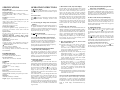
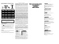
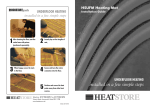
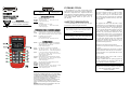
INTRODUCTION OMEGAnet® On-Line Service omega.com HH804W WIRELESS DUAL INPUT RTD DIGITAL THERMOMETER INSTRUCTION SHEET M4552/0707 Shop online at: omega.com e-mail: [email protected] For latest product manuals: omegamanual.info Internet e-mail [email protected] Servicing North America: U.S.A: ISO 9001 Certified Canada: One Omega Drive, Box 4047 Stamford, CT 06907-0047 Tel: (203) 359-1660 FAX: (203) 359-7700 e-mail: [email protected] 976 Bergar Laval (Quebec) H7L 5A1, Canada Tel: (514) 856-6928 FAX: (514) 856-6886 e-mail: [email protected] For immediate technical or application assistance: U.S.A and Canada: Sales Service: 1-800-826-6342/1-800-TC-OMEGA® Customer Service: 1-800-622-2378/1-800-622-BEST® Engineering Service: 1-800-872-9436/1-800-USA-WHEN® TELEX: 996404 EASYLINK: 62968934 CABLE: OMEGA Mexico: En Espanol: (001) 203-359-7803 e-mail: [email protected] FAX: (001) 203-359-7807 [email protected] Benelux: Postbus 8034, 1180 LA Amstelveen, The Netherlands Tel: +31 (0)20 3472121 FAX: +31 (0)20 6434643 Toll Free in Benelux: 0800 0993344 e-mail: [email protected] Servicing Europe: Czech Republic: Frystatska 184, 733 01 Karviná, Czech Republic Tel: +420 (0)59 6311899 FAX: +420 (0)59 6311114 Toll Free: 0800-1-66342 e-mail: [email protected] France: 11, rue Jacques Cartier, 78280 Guyancourt, France Tel: +33 (0)1 61 37 2900 FAX: +33 (0)1 30 57 5427 Toll Free in France: 0800 466 342 e-mail: [email protected] Germany/ Daimlerstrasse 26, D-75392 Deckenpfronn, Germany Austria: Tel: + 49 (0)7056 9398-0 FAX: +49 (0)7056 9398-29 Toll Free in Germany: 0800 639 7678 e-mail: [email protected] United Kingdom: ISO 9002 Certified One Omega Drive, River Bend Technology Centre Northbank, Irlam, Manchester M44 5BD United Kingdom Tel: +44 (0)161 777 6611 FAX: +44 (0)161 777 6622 Toll Free in United Kingdom: 0800-488-488 e-mail: [email protected] It is the policy of OMEGA Engineering, Inc. to comply with all worldwide safety and EMC/EMI regulations that apply. OMEGA is constantly pursuing certification of its products to the European New Approach Directives. OMEGA will add the CE mark to every appropriate device upon certification. The information contained in this document is believed to be correct, but OMEGA accepts no liability for any errors it contains, and reserves the right to alter specifications without notice. WARNING: These products are not designed for use in, and should not be used for, human applications. This instrument is a 4½ digit, compact-sized portable digital thermometer designed to use external 100Ω Platinum RTD as temperature sensor. Temperature indication follows Reference Temperature/Resistance Tables (Pt385 for European Curve, Alpha=.00385. Pt3926 for American Curve, Alpha=.003926. Pt3916 for Japan Curve, Alpha=.003916.) SAFETY INFORMATION It is recommended that you read the safety and operation instructions before using the thermometer. WARNING To avoid electrical shock, do not use this instrument when working voltages at the measurement surface over 24V AC or DC. WARNING To avoid damage or burns, do not make temperature measurement in microwave ovens. FEDERAL COMMUNICATIONS COMMISSION This device complies with Part 15 of the FCC Rules. Operation is subject to the following two conditions:(1) this device may not cause harmful interference, and (2) this device must accept any interference received, including interference that may cause undesired operation. NOTE This equipment has been tested and found to comply with the limits for a Class B digital device, pursuant to Part 15 of the FCC Rules. These limits are designed to provide reasonable protection. This equipment generates, uses and can radiated radio frequency energy and, if not installed and used in accordance with the instructions, may cause harmful interference to radio communications. However, there is no guarantee that interference will not occur in a particular installation If this equipment does cause harmful interference to radio or television reception, which can be determined by turning the equipment off and on, the user is encouraged to try to correct the interference by one or more of the following measures: - Reorient or relocate the receiving antenna. - Increase the separation between the equipment and receiver. - Connect the equipment into an outlet on a circuit different from that to which the receiver is connected. - Consult the dealer or an experienced radio/TV technician for help. Shielded interface cables must be used in order to comply with emission limits. Changes or modifications not expressly approved by the party responsible for compliance could void the user‘s authority to operate the equipment. WIRELESS NOTE Wireless receiver must keep a distance at least 40cm from the meter and meter to meter distance must be at least 30cm. SPECIFICATIONS OPERATING INSTRUCTIONS ELECTRICAL 1. “ ” Power Button Temperature Scale: Celsius or Fahrenheit user-selectable Measurement Range: Pt385(100Ω) -200°C to 800°C, (-328°F to 1472°F) Pt3916/Pt3926(100Ω) -200°C to 630°C, (-328°F to 1166°F) Resolution: 0.1°C or 0.2°F Accuracy: Accuracy is specified for operating temperatures over the range of 18°C to 28°C (64°F to 82°F), for 1 year, not including RTD probe error. ±(0.05% rdg + 0.2°C) on °C scale ±(0.05% rdg + 0.4°F) on °F scale Temperature Coefficient: 0.1 times the applicable accuracy specification per °C from 0°C to 18°C and 28°C to 50°C (32°F to 64°F and 82°F to 122°F). Input Protection: 24V dc or 24V ac rms maximum input voltage on any combination of input pins. Maximum Differential Common Mode Voltage (Maximum Voltage between T1 and T2 during measurement): 1volt. Reading Rate: 1 time per second. Input Connector: Accepts for RTD 4 wires subminiature 4-Prong type connectors (flat blades spaced 7.9mm, center to center). Wireless Features: Frequency range: 910~920MHz Low current consumption less than 1mA The transmitting distance can reach 25M without magnetic interference. ENVIRONMENTAL Ambient Operating Ranges: 0°C to 50°C (32°F to 122°F) <80% R.H. Storage Temperature: -20°C to 60°C (-4°F to 140°F) <70% R.H. GENERAL Display: 4½ digit liquid crystal display (LCD) with maximum reading of 19999. Overload: “----.-” or “OL” is display. Battery: 1.5V x 4 PCS (SIZE AAA) UM-4 R03. Battery Life: 200 hours typical with carbon zinc battery. Auto power off: 30 minutes, press power key to resume operation. Dimensions: 160mm(H) x83mm(W) x 38mm(D). Weight: Approx. 255g including batteries. The “ ” key turns the thermometer on or off. In the SET mode cannot be powered off. Exit SET mode to power off. APO function mode Press “ ” power key for more than 6 seconds to disable the auto-power function. The display will show “APO OFF”. 2. °C/°F Selecting the Temperature Scale (Main display) Reading the main displayed in either degrees Celsius(°C) or degrees Fahrenheit(°F). When the thermometer is turned on, it is set to the temperature scale that was in use when the thermometer was last turned off. To change the temperature scale, press the “°C/°F” key. 3. “ ” Display Back-Light Press the “ ” key to turn on or turn off the Back-Light. 4. T1 T2/T1-T2 Main display Input Selection The input selection indicates which input is selected for main display; T1 probe, T2 probe or the difference between the two probes (T1-T2). When the thermometer is turned on, it is set to T1, when main display input selected T1, then T1 input can select alternate of probe by pressing Pt385/Pt3926/Pt3916 key switch. 5. TYPE(Pt385/Pt3926/Pt3916) Input RTD Probe Select (only Main display) The “TYPE” key switches the T1 input to select the Pt385, Pt3926 or Pt3916 RTD probe as input, when main display input selected T1. When the thermometer is turned on, it is set to the probe selected that was in use when the thermometer was last turned off. 6. MIN/MAX with Time record mode (only Main display) Press “MIN/MAX” key to enter the MIN MAX Recording mode, (displays the Maximum reading with time, Minimum reading with time and Average reading stored in record mode). In the this mode the automatic power-off feature is disabled and “ ” key, “°C/°F” key, “REL” key, “SET” key, “Hi/Lo Limits” key and main display “T1 T2 T1-T2” key, “TYPE” key are disabled. The beeper emits a tone when a new minimum or maximum value is recorded. Press “MIN/MAX” key to cycle through the MAX, MIN and AVG readings. If an overload is recorded, the averaging function is stopped. In this mode, press the “HOLD” key to stop the recording of readings, all values are held, press again to restart recording. To prevent accidental loss of MIN, MAX and AVG data, this mode can only be cancelled by pressing and holding the “MIN/MAX” key for 2 seconds. All recorded readings are erased. 7. REL Relative mode (only Main display) Press the “REL” key to enter the relative mode, zero the display, and store the displayed Reading as a reference value. REL is shown on the display. Press “REL” key again to exit the relative mode. The relative reference value can also be entered by the user. (See “SET mode” later in this manual). When the desired relative value has been entered, press “REL” key to enter the relative mode and than press “SET” key use the entered relative value as a reference value. Press “REL” key again to exit the relative mode. In the relative mode, the value (can not >±1999.9 counts) shown on the LCD is always the difference between the stored reference and the present reading. 8. HOLD mode (only Main display) Press the “HOLD” key to enter the Data Hold mode, the “HOLD” annunciator is displayed. When HOLD mode is selected, the thermometer held the present readings and stops all further measurements. Press the “HOLD” key again to cancel HOLD mode causing thermometer to resume taking measurements. In the MIN/MAX recording mode, press “HOLD” key to stop the recording. Press “HOLD” key again to resume recording. (Previously recorded read are not erased). 9. SET mode (Relative value set, Time set and Hi/Lo Limits value set) 9.1 Press the “SET” key to enter relative values SET mode (Press “ENTER” key to skip setting relative value). = = = =.= is displayed on the main display. The relative value is entered via overlay numbers, press overlay “ENTER” key to store the relative value, and advance to elapsed time set mode. 9.2 Elapsed time set mode, (Press ENTER key to skip Elapsed time set mode) =.= = = : = = is displayed in second and third display. Time (hours, minutes, seconds) value is entered via overlay numbers, press overlay “ENTER” key to store time value. Elapsed time starts from set time value. 9.3 Hi Limit value set mode, (Press “ENTER” key to skip Hi Limit value set mode), = = = =.= is displayed in main display, Hi Limit value is entered via overlay numbers, then press “ENTER” key to store the Hi Limit value. = = = =.= is displayed in main display, Lo Limit value is entered via overlay numbers, then press overlay “ENTER” key to store the Lo Limit value and exit SET mode. 9.4 When the thermometer is turned on it uses the relative value and Hi/Lo Limits values that were entered when thermometer was last in use. 10. T1/T2 T1-T2 second display Input Selection The input selection indicates which input is selected for second display; T1 probe, T2 probe or the difference between the two probes (T1-T2), when the thermometer is turned on, it is set to T2 input can select alternate of probe by second display Pt385/Pt3926/Pt3916 key switch. 11. TYPE(Pt385/Pt3926/Pt3916) Input RTD Probe select (second display) The Pt385/Pt3926 key switches the T2 input to select the Pt385, Pt3926 or Pt3916 RTD probe as input, when second display input selected T2. When the thermometer is turned on, it is set to the RTD selected that was in use when the thermometer was last turned off. 12. Hi/Lo Limits mode (only Main display) Press “Hi/Lo Limits” key to enter the Hi/Lo Limits comparative mode. When the input temperature value exceeds the Hi or Lo Limits value, the beeper emits a continuous or pulsed tone. Press “Hi/Lo Limits” key again to exit the Hi/Lo Limits mode. 13. WIRELESS MODE: Press the “ ” key for more than two seconds to start wireless function. Press the “ ” key again for another two seconds to stop wireless function. The wireless mode will shut down if there is no wireless signal for two minutes. To SET CH/ID to 00,00, press the “Hi/Lo Limits” key and “ ” power key for more than 6 seconds with the meter powered down. The meter will set channel and ID to 00,00 status. The second display will show 00, which means that the channel and ID has been set to 00. To check the channel and ID of the meter: When the meter is off, press “°C/°F” key and “ ” for 5 seconds, LCD’s main display will show channel number, the second display will show ID number. RTD PROBE CONNECTION TEMPERATURE VSRESISTANCE TABLE (ITS90) °C -200°C -100°C 0°C 100°C 200°C 300°C 400°C 500°C 600°C 700°C 800°C Pt385 18.521Ω 60.256Ω 100.000Ω 138.505Ω 175.856Ω 212.052Ω 247.092Ω 280.977Ω 313.708Ω 345.280Ω 375.700Ω Pt3926 16.996Ω 59.479Ω 100.000Ω 139.272Ω 177.362Ω 214.275Ω 250.018Ω 284.591Ω 317.994Ω - Pt3916 17.057Ω 59.565Ω 100.000Ω 139.171Ω 177.155Ω 213.957Ω 249.584Ω 284.036Ω 317.313Ω - OPERATOR MAINTENANCE WARNING To avoid possible electrical shock, disconnect the thermocouple connectors from the thermometer before removing the cover. Battery Replacement 1. Power is supplied by 4pcs 1.5V (AAA SIZE) UM-4 R03. 2. The “ ” appears on the LCD display when replacement is needed. To replace battery remove screw from back of meter and lift off the battery cover. 3. Remove the battery from battery contacts and replace. 4. When not in use for long periods remove battery. 5. Do not store in locations with high temperatures, or high humidity. Cleaning Periodically wipe the case with a damp cloth and detergent, do not use abrasives or solvents. *Software Operation manual is on the Software disk. WARRANTY / DISCLAIMER OMEGA ENGINEERING, INC. warrants this unit to be free of defects in materials and workmanship for a period of 13 months from date of purchase. OMEGA’s WARRANTY adds an additional one (1) month grace period to the normal one (1) year product warranty to cover handling and shipping time. This ensures that OMEGA’s customers receive maximum coverage on each product. If the unit malfunctions, it must be returned to the factory for evaluation. OMEGA’s Customer Service Department will issue an Authorized Return (AR) number immediately upon phone or written request. Upon examination by OMEGA, if the unit is found to be defective, it will be repaired or replaced at no charge. OMEGA’s WARRANTY does not apply to defects resulting from any action of the purchaser, including but not limited to mishandling, improper interfacing, operation outside of design limits, improper repair, or unauthorized modification. This WARRANTY is VOID if the unit shows evidence of having been tampered with or shows evidence of having been damaged as a result of excessive corrosion; or current, heat, moisture or vibration; improper specification; misapplication; misuse or other operating conditions outside of OMEGA’s control. Components which wear is not warranted, include but are not limited to contact points, fuses, and triacs. OMEGA is pleased to offer suggestions on the use of its various products. However, OMEGA neither assumes responsibility for any omissions or errors nor assumes liability for any damages that result from the use of its products in accordance with information provided by OMEGA, either verbal or written. OMEGA warrants only that the parts manufactured by it will be as specified and free of defects. OMEGA MAKES NO OTHER WARRANTIES OR REPRESENTATIONS OF ANY KIND WHATSOEVER, EXPRESS OR IMPLIED, EXCEPT THAT OF TITLE, AND ALL IMPLIED WARRANTIES INCLUDING ANY WARRANTY OF MERCHANTABILITY AND FITNESS FOR A PARTICULAR PURPOSE ARE HEREBY DISCLAIMED. LIMITATION OF LIABILITY: The remedies of purchaser set forth herein are exclusive, and the total liability of OMEGA with respect to this order, whether based on contract, warranty, negligence, indemnification, strict liability or otherwise, shall not exceed the purchase price of the component upon which liability is based. In no event shall OMEGA be liable for consequential, incidental or special damages. CONDITIONS: Equipment sold by OMEGA is not intended to be used, nor shall it be used: (1) as a “Basic Component” under 10 CFR 21 (NRC), used in or with any nuclear installation or activity; or (2) in medical applications or used on humans. Should any Product(s) be used in or with any nuclear installation or activity, medical application, used on humans, or misused in any way, OMEGA assumes no responsibility as set forth in our basic WARRANTY / DISCLAIMER language, and, additionally, purchaser will indemnify OMEGA and hold OMEGA harmless from any liability or damage whatsoever arising out of the use of the Product(s) in such a manner. RETURN REQUESTS / INQUIRIES Direct all warranty and repair requests / inquiries to the OMEGA Customer Service Department. BEFORE RETURNING ANY PRODUCT(S) TO OMEGA, PURCHASER MUST OBTAIN AN AUTHORIZED RETURN (AR) NUMBER FROM OMEGA’S CUSTOMER SERVICE DEPARTMENT (IN ORDER TO AVOID PROCESSING DELAYS). The assigned AR number should then be marked on the outside of the return package and on any correspondence. The purchaser is responsible for shipping charges, freight, insurance and proper packaging to prevent breakage in transit. FOR WARRANTY RETURNS, please have the following information available BEFORE contacting OMEGA: 1. Purchase Order number under which the product was PURCHASED, 2. Model and serial number of the product under warranty, and 3. Repair instructions and/or specific problems relative to the product. FOR NON-WARRANTY REPAIRS, consult OMEGA for current repair charges. Have the following information available BEFORE contacting OMEGA: 1. Purchase Order number to cover the COST of the repair, 2. Model and serial number of the product, and 3. Repair instructions and/or specific problems relative to the product. OMEGA’s policy is to make running changes, not model changes, whenever an improvement is possible. This affords our customers the latest in technology and engineering. OMEGA is a registered trademark of OMEGA ENGINEERING, INC. © Copyright 2007 OMEGA ENGINEERING, INC. All rights reserved. This document may not be copied, photocopied, reproduced, translated, or reduced to any electronic medium or machine-readable form, in whole or in part, without the prior written consent of OMEGA ENGINEERING, INC. Where Do I Find Everything I Need for Process Measurement and Control? OMEGA…Of Course! Shop online at omega.com TEMPERATURE Thermocouple, RTD & Thermistor Probes, Connectors, Panels & Assemblies Wire: Thermocouple, RTD & Thermistor Calibrators & Ice Point References Recorders, Controllers & Process Monitors Infrared Pyrometers PRESSURE, STRAIN AND FORCE Transducers & Strain Gages Load Cells & Pressure Gages Displacement Transducers Instrumentation & Accessories FLOW/LEVEL Rotameters, Gas Mass Flowmeters & Flow Computers Air Velocity Indicators Turbine/Paddlewheel Systems Totalizers & Batch Controllers pH/CONDUCTIVITY pH Electrodes, Testers & Accessories Benchtop/Laboratory Meters Controllers, Calibrators, Simulators & Pumps Industrial pH & Conductivity Equipment DATA ACQUISITION Data Acquisition & Engineering Software Communications‐Based Acquisition Systems Plug‐in Cards for Apple, IBM & Compatibles Datalogging Systems Recorders, Printers & Plotters HEATERS Heating Cable Cartridge & Strip Heaters Immersion & Band Heaters Flexible Heaters Laboratory Heaters ENVIRONMENTAL MONITORING AND CONTROL Metering & Control Instrumentation Refractometers Pumps & Tubing Air, Soil & Water Monitors Industrial Water & Wastewater Treatment pH, Conductivity & Dissolved Oxygen Instruments