1
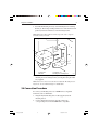
Heading Sensor
Owner’s
Handbook
Document number: 81124_3
Date: 1st May 2001
124_3cov.p65
1
09/05/01, 11:29
Copyright © Raymarine Limited 2001
124_3cov.p65
2
09/05/01, 11:29
i
Preface
Important information
WARNING
Although your Heading Sensor is designed to give accurate and
reliable performance, it should serve only as an aid to navigation
and should never lead to the erosion of good seamanship. Always
maintain a permanent watch and be aware of situations as they
develop.
EMC conformance
All Raymarine equipment and accessories are designed to the best
industry standards for use in the leisure marine environment.
The design and manufacture of Raymarine equipment and accessories
conform to the appropriate Electromagnetic Compatibility (EMC)
standards, but correct installation is required to ensure that performance
is not compromised.
Handbook information
To the best of our knowledge, the information in this handbook was
correct when it went to press. However, the Raymarine policy of
continuous product improvement may change product specifications
without notice. Consequently, unavoidable differences may occur
between the product and the handbook from time to time, for which
Raymarine cannot accept liability
124_3pre.p65
1
09/05/01, 11:29
ii
124_3pre.p65
Heading Sensor Owner’s Handbook
2
09/05/01, 11:29
iii
Preface
Contents
Important information .......................................................... i
WARNING ......................................................................... i
EMC conformance ............................................................. i
Handbook information ....................................................... i
Chapter 1: Introduction ......................................................... 1
1.1 Handbook information ................................................ 1
1.2 Description .................................................................. 1
Chapter 2: Maintenance & Fault Finding ............................ 3
2.1 Servicing and Safety ................................................... 3
2.2 Maintenance ................................................................ 3
2.3 Fault Finding ............................................................... 4
Assistance .................................................................... 4
Chapter 3: Installation ........................................................... 5
3.1 Before you Begin ........................................................ 5
Components ................................................................. 5
Basic Installation Tools ............................................... 5
EMC Installation Guidelines ....................................... 5
Suppression Ferrites .............................................. 6
Connections to Other Equipment ........................... 7
3.2 Siting the Heading Sensor ........................................... 7
3.3 Installation Procedure ................................................. 8
3.4 Connection Procedure ................................................. 9
124_3pre.p65
3
09/05/01, 11:29
iv
Heading Sensor Owner’s Handbook
Chapter 4: Calibration ......................................................... 11
4.1 Introduction ............................................................... 11
EMC Conformance ................................................... 11
4.2 Continuous Deviation Correction ............................. 11
4.3 Heading Alignment ................................................... 12
Heading Sensor Specification ............................................ 15
124_3pre.p65
4
09/05/01, 11:29
1
Chapter 1: Introduction
Chapter 1: Introduction
Thank you for purchasing a Raymarine product. We are sure your
Heading Sensor will give you many years of trouble-free operation.
This Heading Sensor is designed to provide reliable performance, even
under the most demanding conditions.
5-1
D550
1.1 Handbook information
This handbook contains important information on the installation,
calibration and maintenance of your Heading Sensor. Please read the
handbook thoroughly, so that you get the best results from this product.
1.2 Description
The Raymarine Heading Sensor consists of an oil-filled sphere
suspended in a custom built “swing bracket”, together with associated
electronics.
The Heading Sensor transmits magnetic compass heading data to
equipment that is NMEA 0183 compatible, such as radars, RayData
displays, and RayPilot autopilot systems.
124_3c01.p65
1
09/05/01, 11:29
2
124_3c01.p65
Heading Sensor Owner’s Handbook
2
09/05/01, 11:29
3
Chapter 2: Maintenance & Fault Finding
Chapter 2: Maintenance & Fault Finding
2.1 Servicing and Safety
• Raymarine equipment should be serviced only by authorized
Raymarine service technicians. They will ensure that service
procedures and replacement parts used will not affect performance.
There are no user serviceable parts in any Raymarine product.
• Some products generate high voltages, so never handle the cables/
connectors when power is being supplied to the equipment.
• When powered up, all electrical equipment produces
electromagnetic fields. These can cause adjacent pieces of electrical
equipment to interact with one another, with a consequent adverse
effect on operation. In order to minimise these effects and enable
you to get the best possible performance from your Raymarine
equipment, guidelines are given in the installation instructions, to
enable you to ensure minimum interaction between different items
of equipment, i.e. ensure optimum Electromagnetic Compatibility
(EMC).
• Always report any EMC-related problem to your nearest Raymarine
dealer. We use such information to improve our quality standards.
• In some installations, it may not be possible to prevent the
equipment from being affected by external influences. In general
this will not damage the equipment but it can lead to spurious
resetting action, or momentarily may result in faulty operation.
• Always switch off the power to Raymarine equipment before
working on it.
2.2 Maintenance
The Raymarine Heading Sensor is a sealed unit. Maintenance
procedures are therefore limited to the following periodical checks:
• Examine the cable for signs of damage, such as chafing, cuts or
nicks
• Make sure that the Heading Sensor is still attached securely to the
bulkhead
124_3c02.p65
3
09/05/01, 11:30
4
Heading Sensor Owner’s Handbook
2.3 Fault Finding
All Raymarine products are subjected to comprehensive test and
quality assurance programmes, prior to packing and shipping.
However, if your Heading Sensor should develop a fault , please refer
to the following table to identify the most likely cause and the
corrective action required to restore normal operation.
Problem
Correction
No compass heading data available.
Check that the cable connecting the
Heading Sensor to the NMEA
instrument or system is firmly attached
and undamaged.
The compass heading displayed on
the associated instrument is not the
same as the ship’s compass.
Heading Sensor has not been linearised.
Linearisation procedure unsuccessful.
Move the Heading Sensor to a new
location and try again.
Assistance
If you still have a problem after referring to the table above, contact
your local dealer or Raymarine Product Support Department for further
advice.
124_3c02.p65
4
09/05/01, 11:30
5
Chapter 3: Installation
Chapter 3: Installation
This chapter describes how to install the Heading Sensor, using
everyday hand tools.
3.1 Before you Begin
Before you begin, make sure that you have the all the required
components and tools (listed below) to hand.
Note: Before attempting any installation, you should read the
Electromagnetic Compatibility (EMC) installation and service
guidelines provided under EMC Installation Guidelines.
Components
The Raymarine Heading Sensor includes the following standard
components:
• Heading Sensor
• “Swing” bracket
• Self tapping screws (4)
• 6ft (2m) cable, with molded Heading Sensor plug on one end
If you are installing the Heading Sensor at a distance from an NMEA
instrument or system, you may also need a 16.25ft (5m) NMEA
accessory cable.
Basic Installation Tools
• Cross head screwdriver
• Electric/hand drill
• 1mm (0.39in) drill bit
EMC Installation Guidelines
All Raymarine equipment and accessories are designed to the best
industry standards for use in the recreational marine environment.
Their design and manufacture conforms to the appropriate
Electromagnetic Compatibility (EMC) standards, but correct
installation is required to ensure that performance is not compromised.
124_3c03.p65
5
09/05/01, 11:30
6
Heading Sensor Owner’s Handbook
Although every effort has been taken to ensure that they will perform
under all conditions, it is important to understand what factors could
affect the operation of the product.
The guidelines given here describe the conditions for optimum EMC
performance, but it is recognized that it may not be possible to meet all
of these conditions in all situations. To ensure the best possible
conditions for EMC performance within the constraints imposed by
any location, always ensure the maximum separation possible between
different items of electrical equipment.
For optimum EMC performance, it is recommended that wherever
possible:
• Raymarine equipment and cables connected to it are:
• At least 3 ft (1 m) from any equipment transmitting or cables
carrying radio signals e.g. VHF radios, cables and antennas. In
the case of SSB radios, the distance should be increased to 7 ft
(2 m).
• More than 7 ft (2 m) from the path of a radar beam. A radar
beam can normally be assumed to spread 20 degrees above and
below the radiating element.
• The equipment is supplied from a separate battery from that used for
engine start. Voltage drops below 10 V in the power supply to our
products, and starter motor transients, can cause the equipment to
reset. This will not damage the equipment, but may cause the loss of
some information and may change the operating mode.
• Raymarine specified cables are used. Cutting and rejoining these
cables can compromise EMC performance and must be avoided
unless doing so is detailed in the installation manual.
• If a suppression ferrite is attached to a cable, this ferrite should not
be removed. If the ferrite needs to be removed during installation it
must be reassembled in the same position.
Suppression Ferrites
The following illustration shows typical cable suppression ferrites used
with Raymarine equipment. Always use the ferrites supplied by
Raymarine.
124_3c03.p65
6
09/05/01, 11:30
7
Chapter 3: Installation
D3548-2
Connections to Other Equipment
If your Raymarine equipment is to be connected to other equipment
using a cable not supplied by Raymarine, a suppression ferrite MUST
always be attached to the cable near the Raymarine unit.
3.2 Siting the Heading Sensor
The Heading Sensor must be fitted to a vertical or horizontal bulkhead
(preferably forward facing), away from large ferrous objects such as the
engine and other magnetic devices.
If you have any doubts about the magnetic suitability of a chosen
location, attach a hand bearing compass to the chosen site and then turn
your vessel through 360°. Differences between the hand-bearing
compass and the boat’s compass should not exceed 10° on any heading.
The Heading Sensor should be positioned as close as possible to the
pitch and roll centre of the vessel, as shown in the following diagram.
124_3c03.p65
7
09/05/01, 11:30
8
Heading Sensor Owner’s Handbook
0.3L to 0.5L
L
X
0.3L to 0.5L
L
D194-2
The compass is normally bulkhead mounted below decks. However, it
can be mounted above deck on steel vessels. Although it is
weatherproof, performance may be impaired due to the increased
motion if it is mounted above deck.
3.3 Installation Procedure
To install the heading Sensor:
1. Hold the Heading Sensor mounting bracket (4) against the
selected bulkhead.
2. Outline the four fixing holes in the Heading Sensor mounting
bracket (4).
3. Drill four pilot holes for the self-tapping screws.
4. Secure the Heading Sensor mounting bracket (4) to the bulkhead
using the four self-tapping screws (3) provided. The embossed
arrow on the back of the bracket must be pointing skywards.
Note: The Heading Sensor must be within 10° of the vertical and,
ideally, positioned at the pitch and roll centre of the vessel.
124_3c03.p65
8
09/05/01, 11:30
9
Chapter 3: Installation
5. Assemble the Heading Sensor (1) to the Heading Sensor mounting
bracket (4). The shaft protruding from the base of the unit must click
positively into the slot in the base of the mounting bracket.
Note: The boat symbol embossed on the top of the active compass
should be facing forwards.
1
2
3
4
1 Heading Sensor
2 Allen bolt
3 Self-tapping screw
4 Heading Sensor mounting bracket
D5506-1
6. Pass the Allen bolt (2) through the aperture in the top of the
Heading Sensor mounting bracket (4) and tighten using the Allen
key supplied.
Note: You may need to loosen this later to adjust the Heading Sensor
alignment , as described in Chapter 4, Calibration.
3.4 Connection Procedure
To connect your Heading Sensor to an NMEA 0183 compatible
instrument, such as a XX Radar:
1. Plug the 6ft (2m) Heading Sensor cable (supplied) into the
Heading Sensor.
2. Connect the black and red wires from the cable to the
corresponding wires from the NMEA 0183 compatible
124_3c03.p65
9
09/05/01, 11:30
10
Heading Sensor Owner’s Handbook
equipment, using a suitable connector block, as shown in the
diagram below. A 16.25ft (5m) NMEA accessory cable is
available for more distant connection if required.
Red
NMEA power
Yellow
+ NMEA data
Black
-- NMEA data
Ground
D5508-1
Check the handbook supplied with NMEA 0183 compatible
equipment, to determine the correct pin connections for the heading
sensor input. For example, the connections for a XX Radar are shown
in the following diagram.
XX Radar
J404 NMEA Chassis Connector
viewed from the solder side of the
G263129-17k connector
Heading Sensor
1
6
5
2
4
3
(1) NMEA + (Navigation aid)
(2) NMEA - (Navigation aid)
Red
Yellow
Black
(5) 12VDC (Heading sensor)
(3) NMEA + (Heading sensor)
(4) NMEA - (Heading sensor)
(6) Ground (Heading sensor)
D5507-1
124_3c03.p65
10
09/05/01, 11:30
11
Chapter 4: Calibration
Chapter 4: Calibration
4.1 Introduction
The Raymarine Heading Sensor must be calibrated to ensure that the
transmitted compass heading information is accurate. This procedure
should be carried out before the unit is used as a navigational aid.
The calibration consists of two components:
• Compass Linearisation: This detects heading errors caused by iron
objects, such as engines or gas bottles. Once such errors have been
detected, the Heading Sensor corrects them automatically.
• Heading Alignment: This is required to match the displayed
heading to a known heading or transit. You can align the Heading
Sensor with your ship’s compass, providing your ship’s compass is
accurate.
The compass linearisation is performed using the Raymarine Heading
Sensor’s Continuous Deviation Correction. The Heading Sensor
monitors the deviation continuously and, if the required conditions are
met, updates its correction data.
This chapter describes the Continuous Deviation Correction procedure
and the heading alignment procedure.
EMC Conformance
• Always check the installation before going to sea to make sure that it
is not affected by radio transmissions, engine starting etc.
4.2 Continuous Deviation Correction
The Raymarine Heading Sensor normally monitors magnetic deviation
continuously. Every time your vessel completes a 360° turn within the
time constraints of the system, the compass checks the new deviation
data and updates its correction data if required.
Deviation data is only used if the vessel has completed a 360° turn in
not less than three minutes, without any sudden increases in speed, and
if this provides more accurate data than that already stored.
124_3c04.p65
11
09/05/01, 11:30
12
Heading Sensor Owner’s Handbook
To ensure that the compass has received accurate data, perform the
following procedure:
1. Choose a calm day, and select an area of open water. Ideally, the
current and tide effects should be at a minimum.
2. Calculate the size of circle you need to make in order to keep your
turn rate down to not less than 45 seconds for each 90° of turn.
You can turn more slowly than this, and you do not need to keep to
an exact circle, but if you turn too quickly the deviation data will be
ignored.
3. Turn your vessel continuously through two full circles (720°), at a
slow, steady speed, keeping the vessel level. You can go either
clockwise or anti-clockwise.
4. Ideally, continue to turn through a further two full circles to ensure
you have obtained accurate data.
The Heading Sensor will now correct all heading readings using the
variation data obtained.
4.3 Heading Alignment
After you have performed the Continuous Deviation Correction
procedure, you should check the heading alignment. You can do so
using one or both of the following techniques:
• Compare the heading information on your display instrument (such
as a XX Radar or RayData) with the ship’s magnetic compass for
several headings.
Note: Your magnetic compass must be accurate, and should have
been calibrated recently.
• Choose reference points from a chart, and navigate between them.
Then compare the readings from your Heading Sensor with the
actual chart courses.
If the Heading Sensor’s readings differ from the actual readings by a
constant amount, you need to correct the heading alignment. This is
achieved by adjusting the position of the compass, as follows:
1. Loosen the Heading Sensor mounting slightly, so that you can
rotate the sensor. To do this, use the Allen key supplied with the
Heading Sensor to loosen the Allen bolt in the top of the Heading
Sensor mounting bracket (see page 7).
124_3c04.p65
12
09/05/01, 11:30
13
Chapter 4: Calibration
2. If the Heading Sensor’s readings are less than the actual readings,
rotate the sensor slightly clockwise.
If the Heading Sensor’s readings are greater than the actual
readings, rotate the sensor slightly anti-clockwise.
3. Check the headings again, and repeat step 2 if required.
4. When the headings match, tighten the Allen bolt to hold the sensor
in its new position.
124_3c04.p65
13
09/05/01, 11:30
14
124_3c04.p65
Heading Sensor Owner’s Handbook
14
09/05/01, 11:30
15
Specification
Heading Sensor Specification
Dimensions:
90mm x 100mm x 130mm (3.5in x 3.9 in x 5.1in)
Power Supply:
10 to 16V DC
Power Consumption:
40mA
Operating Temperature:
-10°C to +70°C (14°F to 158°F)
Weight:
450g (1 lb)
Compatability:
NMEA 0183 compatible equipment
Accuracy:
+/- 0.5°
Gimbal Range:
Pitch = +33°, Roll + 45°
Data Output (NMEA):
(10Hz)
HDM (Magnetic Compass Heading)
HDG (Heading only)
124_3spe.p65
15
09/05/01, 11:30
16
124_3spe.p65
Heading Sensor Installation Manual
16
09/05/01, 11:30
84064_8.fm Page 1 Monday, April 9, 2001 4:42 PM
Limited Warranty Certificate
Raymarine warrants each new Light Marine/Dealer Distributor Product to be of good materials and
workmanship, and will repair or exchange any parts proven to be defective in material and
workmanship under normal use for a period of 2 years/24 months from date of sale to end user, except
as provided below.
Defects will be corrected by Raymarine or an authorized Raymarine dealer. Raymarine will, except
as provided below, accept labor cost for a period of 2 years/24 months from the date of sale to end user.
During this period, except for certain products, travel costs (auto mileage and tolls) up to 100 round
trip highway miles (160 kilometres) and travel time of 2 hours, will be assumed by Raymarine only
on products where proof of installation or commission by authorized service agents, can be shown.
Warranty Limitations
Raymarine Warranty policy does not apply to equipment which has been subjected to accident, abuse
or misuse, shipping damage, alterations, corrosion, incorrect and/or non-authorized service, or
equipment on which the serial number has been altered, mutilated or removed.
Except where Raymarine or its authorized dealer has performed the installation, it assumes no
responsibility for damage incurred during installation.
This Warranty does not cover routine system checkouts or alignment/calibration, unless required by
replacement of part(s) in the area being aligned.
A suitable proof of purchase, showing date, place, and serial number must be made available to
Raymarine or authorized service agent at the time of request for Warranty service.
Consumable items, (such as: Chart paper, lamps, fuses, batteries, styli, stylus/drive belts, radar mixer
crystals/diodes, snap-in impeller carriers, impellers, impeller bearings, and impeller shaft) are
specifically excluded from this Warranty.
Magnetrons, Cathode Ray Tubes (CRT), TFT Liquid Crystal Displays (LCD) and cold cathode
fluorescent lamps (CCFL), hailer horns and transducers are warranted for 1 year/12 months from date
of sale. These items must be returned to a Raymarine facility.
All costs associated with transducer replacement, other than the cost of the transducer itself, are
specifically excluded from this Warranty.
Overtime premium labor portion of services outside of normal working hours is not covered by this
Warranty.
Travel cost allowance on certain products with a suggested retail price below $2500.00 is not
authorized. When/or if repairs are necessary, these products must be forwarded to a Raymarine
facility or an authorized dealer at owner’s expense will be returned via surface carrier at no cost to the
owner.
Travel costs other than auto mileage, tolls and two (2) hours travel time, are specifically excluded on
all products. Travel costs which are excluded from the coverage of this Warranty include but are not
limited to: taxi, launch fees, aircraft rental, subsistence, customs, shipping and communication
charges etc. Travel costs, mileage and time, in excess to that allowed must have prior approval in
writing.
TO THE EXTENT CONSISTENT WITH STATE AND FEDERAL LAW:
(1) THIS WARRANTY IS STRICTLY LIMITED TO THE TERMS INDICATED HEREIN, AND
NO OTHER WARRANTIES OR REMEDIES SHALL BE BINDING ON RAYMARINE
INCLUDING WITHOUT LIMITATION ANY WARRANTIES OF MERCHANTABLE OR
FITNESS FOR A PARTICULAR PURPOSE.
(2) Raymarine shall not be liable for any incidental, consequential or special (including punitive or
multiple) damages.
All Raymarine products sold or provided hereunder are merely aids to navigation. It is the
responsibility of the user to exercise discretion and proper navigational skill independent of any
Raymarine equipment.
Document number: 84064-8
April 2001
84064_8.fm Page 2 Monday, April 9, 2001 4:42 PM
Factory Service Centers
United States of America
UK, Europe, Middle East, Far East
Raymarine Inc
22 Cotton Road, Unit D
Nashua, NH 03063-4219, USA
Raymarine Ltd
Anchorage Park, Portsmouth
PO3 5TD, England
Telephone: +1 603 881 5200
Fax: +1 603 864 4756
www.raymarine.com
Telephone: +44 (0)23 9269 3611
Fax: +44 (0)23 9269 4642
www.raymarine.com
Sales & Order Services
Telephone: +1 800 539 5539 Ext. 2333 or
+1 603 881 5200 Ext. 2333
Customer Support
Telephone: +44 (0)23 9271 4713
Fax: +44 (0)23 9266 1228
Technical Support
Telephone: +1 800 539 5539 Ext. 2444 or
+1 603 881 5200 Ext. 2444
Email: [email protected]
Email: [email protected]
Product Repair Center
Telephone: +1 800 539 5539 Ext. 2118
Stick barcode label here
Purchased from
Purchase date
Dealer address
Installed by
Installation date
Commissioned by
Commissioning date
Owner’s name
Mailing address
This portion should be completed and retained by the owner.